Assignment 5-RADIOSS Interfaces & Study of Effect of Notches Challenge
REFER LINK: https://skill-lync.com/student-projects/radioss-interfaces-study-of-effect-of-notches-challenge-2
TITLE: RADIOSS Interfaces & Study of Effect of Notches Challenge
SUMMARY: Here, we have simulate the crash tube model.The crash tube model is provided with a rigid support on its front, while a pushing force at its end so that the impact can be capture, visualize & desired results are carried out. For the crash tube model, we have run it followed by five different cases. From running it as it is, to assigning different interface type followed by changing notches. Finally, we observe how by changing various factors it impacts on crash model. Later we compare all results as follows.
INTRODUCTION: So far the explicit solvers, solving non-linear problems are concerned contacts plays an important role in it. However, its accuracy totally depends on it. So interface modelling is much more important. The Master & Slave segments are defies as interfaces. Various algorithms such as type 7, type 11 are used for final penetrations between masters & slaves. The consists of variable stiffness, node to surface contact & variable stiffness, edge to edge. The Variable stiffness is an important factor as well, however it is under influence of Radioss contact theorey called as Penalty method calculation. It is nothing but, treating slave & master sements as springs which generates a resistive force as a function of penetration.
`i`Create the mesh for bumper assembly,mesh size should be 6mm.
- We import the Geometry and using quick edit option, we have certain operations such as topology,extending edges & togglling to remove any abnormalities.
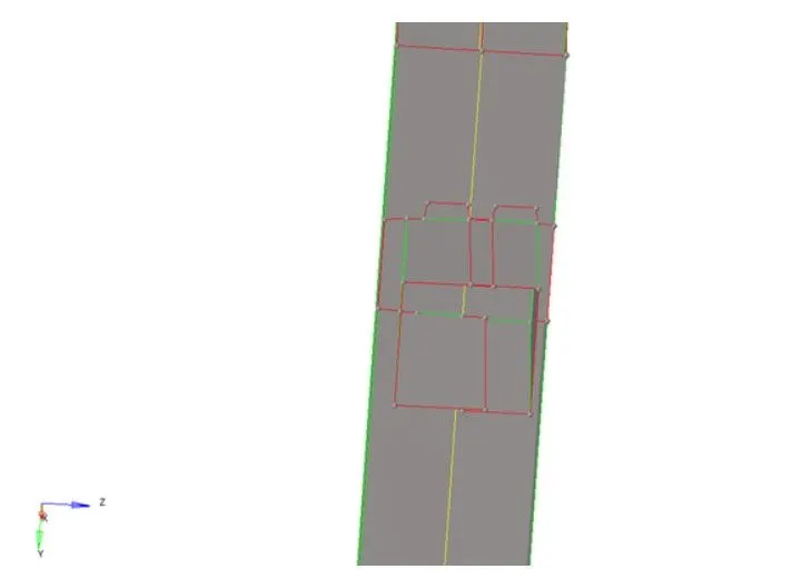 FIG. 1. GEOMETRY EDIT.
- Once done, the geometry is free from errors.
- Now, the geometry is meshed using 2D automesh with an elemental size of 6mm.
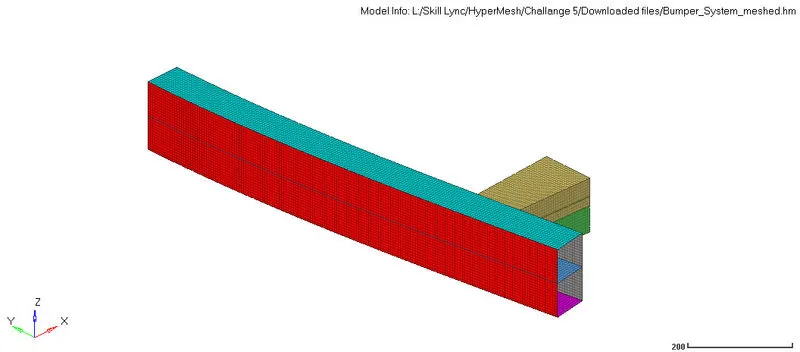
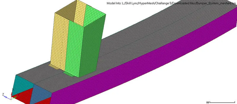 FIG. 2. MESHED MODEL
- The mesh is reviewed later, & checked for any defects.
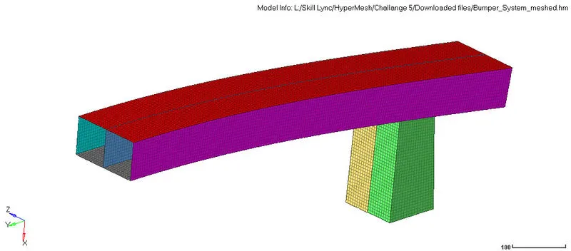 FIG. 3. FINAL MESHED MODEL
`ii` SIX DIFFERENT CASES ARE AS FOLLOWS,
CASE 1: Run the crash tube model as it is.
Procedure-
- We begin by importing solver deck file inside Hypermesh user interface. GO TO FILE>IMPORT>SOLVER DECK>CRASH_TUBE_0000.RAD.
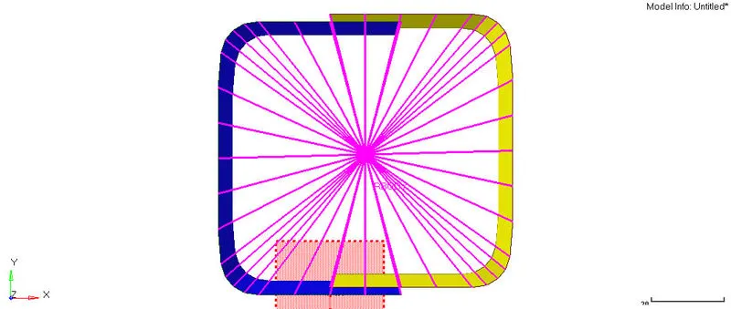
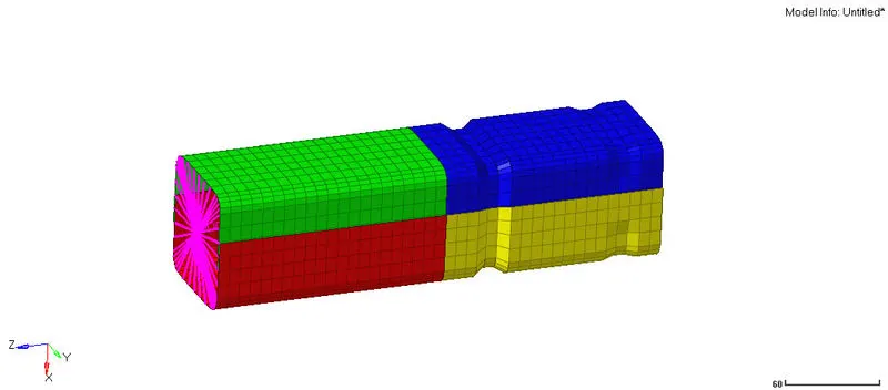 FIG. 1. Model.
- Here, we gonna run this case as it is, without chaning any values.
- We being with reviewing all the material, property cards & interfaces.
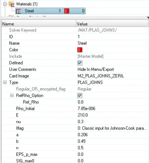
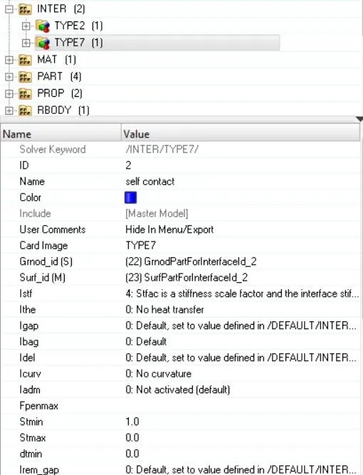 FIG. 2. CARDS
- Now, we bein with simulation, HIT ANALYSIS>RADIOSS>
 FIG. 3. ANALYSIS WINDOW
- A window will appear, which executes simulation. Meanwhile it also consists of all info of our desired results. Later these values can be visualize.
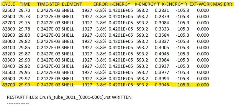 FIG. 4. VALUES
- Later, we switch to Hyperviews to visualize the simulation. The H3D file is loaded inside. The Von Mises Stress is captured
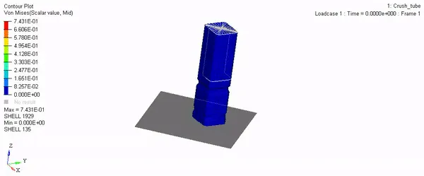 FIG. 5. STRESS CONTOUR.
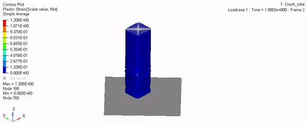 FIG. 6. STRAIN CONTOUR.
- From above, it can be seen that initial penetration occurs & the crash tube begin to deform at the upper notch. The upper notch went to plastic deformation first and eventually it started to bend at bottom notch. The Maximum stress & strain values generated at the conners of the crash tube.
- Now, switching to hypergraph we are able to plots various energies & forces as follows.
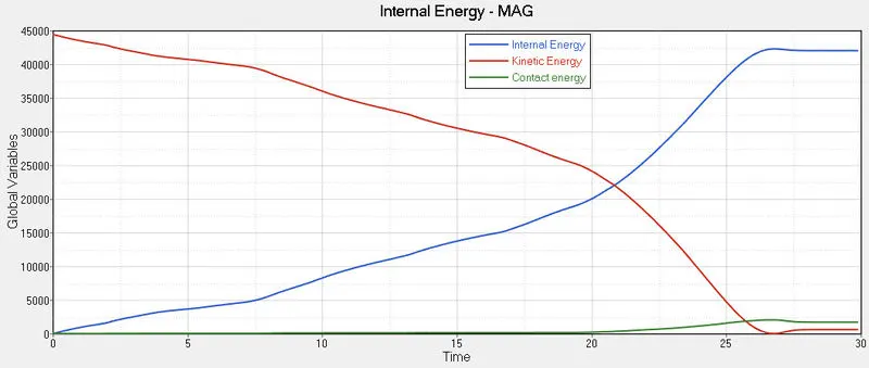 FIG. 7. ENERGIES GRAPH.
- From above, it seems that kinectic energy falls drastically. It happens as the crash tube deforms resulting in conversion into internal energy.
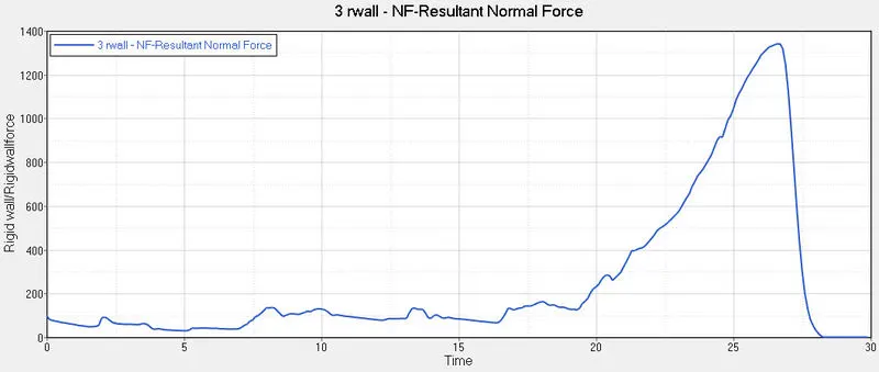 FIG. 8. FORCES GRAPH.
- From above, the resultant force increases at slow pace but peaks after 20 m/s. These occurs due to the corner edges folds the tube and slave nodes penetrates master surface.
CASE 2: Change the Inacti=6 and run.
-
- We import same file from solver deck option. Once imported we ahve to assigned as per mentioned.
- Now, Inacti = 6 is nothing but a Type 7 parameter. It is used to remove initial penetration where possible. The gap is reduced and scaled. Good accuracy can be obtained.
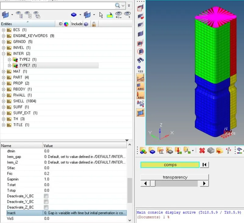 FIG. 9. Inacti.
- Once, the desired parameters has been assigned. We execute the Radioss run.
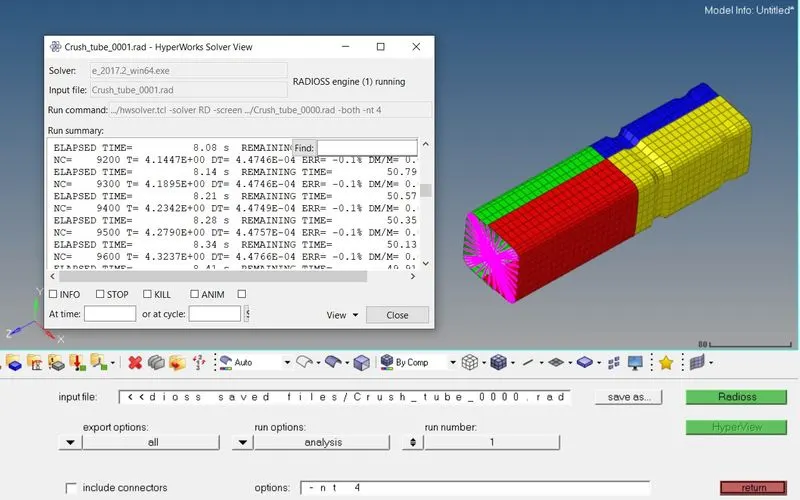 FIG. 10. SOLVER VIEW.
- The various energy, mass error values has been generated as follows.
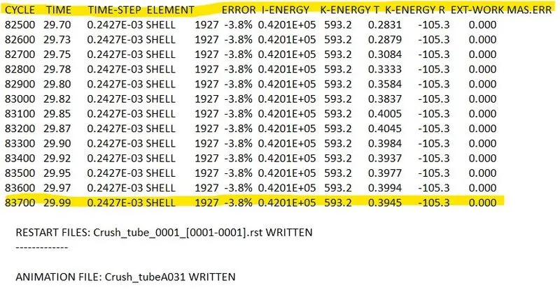 FIG. 11. PARAMETERS VALUES
- Later, we switch to Hyperviews to visualize the simulation. The H3D file is loaded inside. The Von Mises Stress & Srain values are captured.
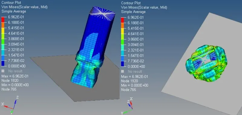 FIG. 11. STRESS VALUES.
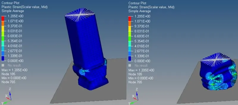 FIG. 12. PLASTIC STRAIN VALUES.
- From above, it seems that values of 1st case and 2nd case are rather same. The only difference is that by assigning Inacti= 6, overall gap is reduced & followed by scaling. Inacti6 removes initial penetration followed by moving nodes by 30% of initial gap to avoid any further contact stability issue.
- Now, switching to hypergraph we are able to plots various energies & forces as follows.
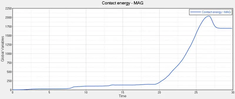 FIG. 13. ENERGY GRAPH
- From Contact energy graph, it shows that after 20m/s it peaks rapidly since the friction constant is defined which results in increase in friction formulation. FIG. 14. RESULTANT FORCES.
CASE 3: Create the type 11 contact and run.
- Now, let's import solver deck file again & in this case we create Type 11 contact from Interface inside solver browser.
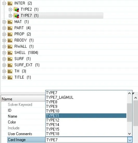
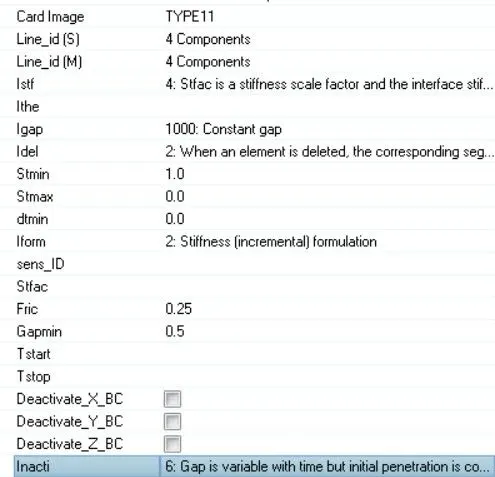 FIG. 15. ASSIGNED PARAMETERS
- The simulation went through, desired values has been generated.
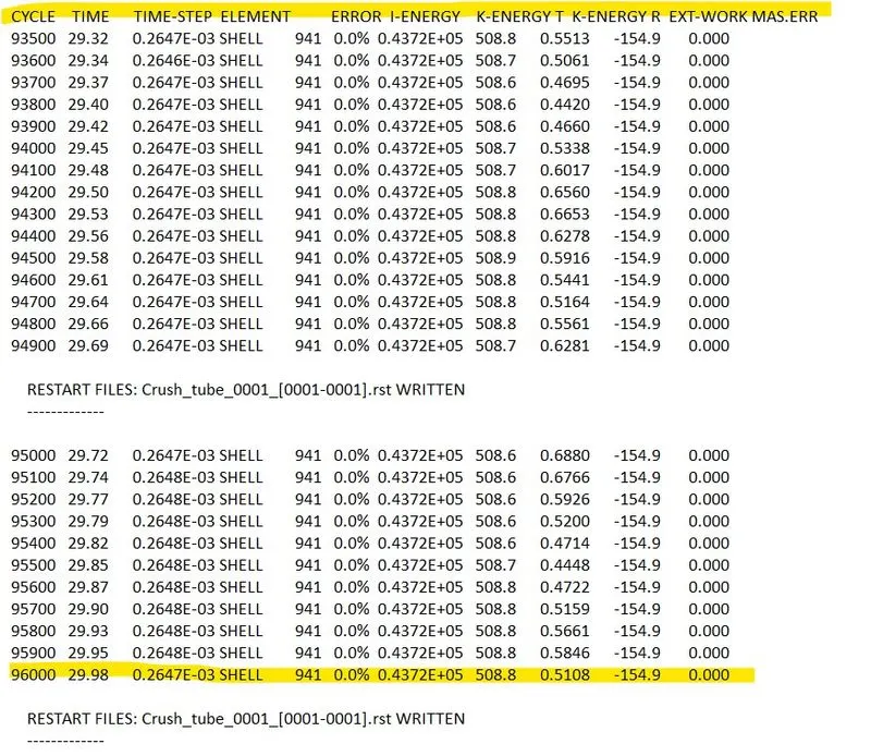 FIG. 15. OUTFILE VALUES.
- Later, we switch to Hyperviews to visualize the simulation. The H3D file is loaded inside. The Von Mises Stress & Srain values are captured.
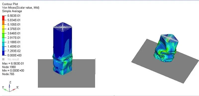 FIG. 16. STRESS VALUES.
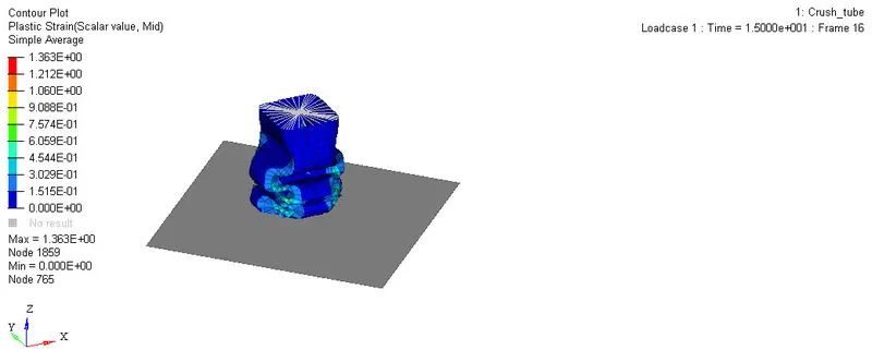 FIG. 16. STRAIN VALUES.
- In this case, after assiggning Type 11 contact the edge to edge intersection is being eleminated. The results won't varry much from earlier.
- Switch to hypergraph we are able to plots various energies & forces as follows.
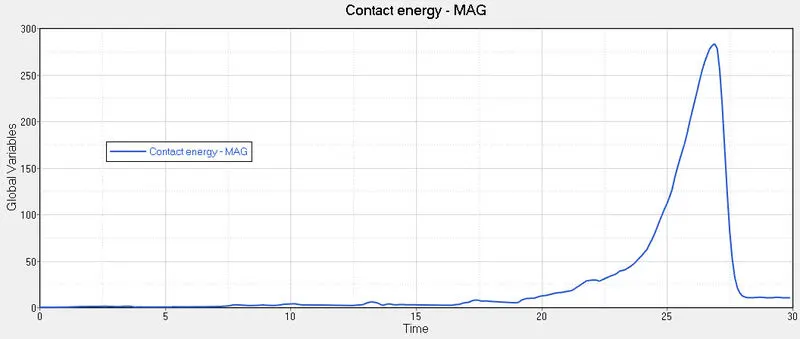 FIG. 17. CONTACT ENERGY.
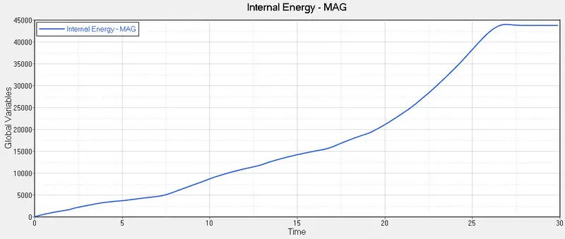 FIG. 18. INTERNAL ENERGY
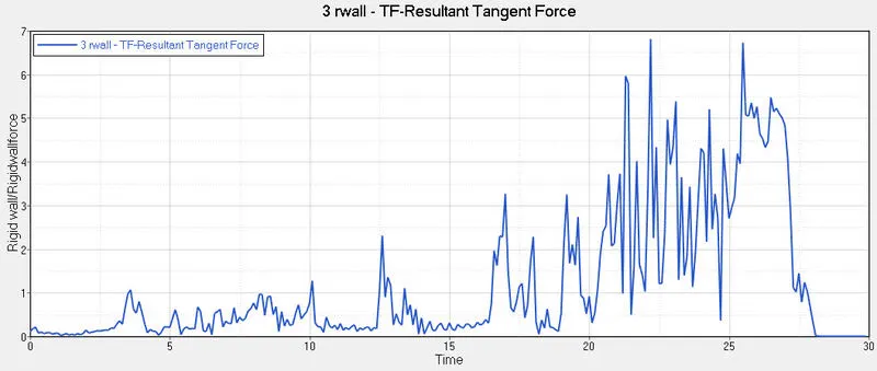 FIG. 18.RESULTANT FORCES.
- Here, energy graphs remain same as per earlier cases. However, there is more fluctuations in Rwall forces its due to type 11 comes in contact with elements & suddenly reaches to peak and decrease as per graph after collision is done.
CASE 4: Remove both notches and remove boundary condition on rigid body node then run.
- We begin with importing solver deck file, then we have to remove the notches followed by its boundary conditions.
- The import model is consider inside Geometry edit panel. The node edit option is selected & nodes are alligned to remove notches.
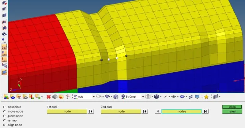 FIG. 19.Geometry EDIT.
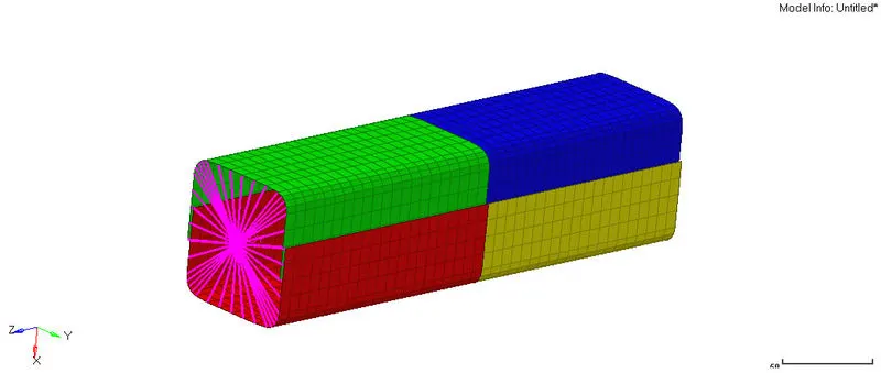 FIG. 20. NOTCH FREE MODEL
- We remove all the Boundary conditions mentioned.
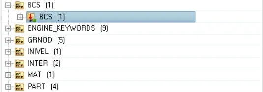 FIG. 21. BOUNDARY CONDITIOND REMOVED
- The Radioss file is run, simulation went through. Results are as follows,
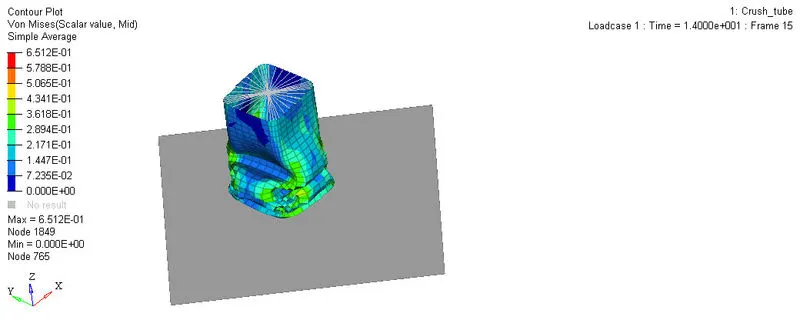 FIG. 22. STRESS VALUES.
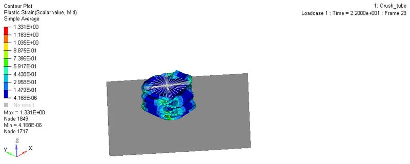 FIG. 22. STRAIN VALUES.
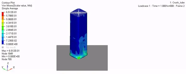
- From above results, its been clearly visualize that the crash tube has uniform section once the notches are removed. The tube begins to deform at the bottom region first followed by the entire component.
- Removal of Notches resultes in Buckling effect at corners only.
- Switch to hypergraph we are able to plots various energies & forces as follows.
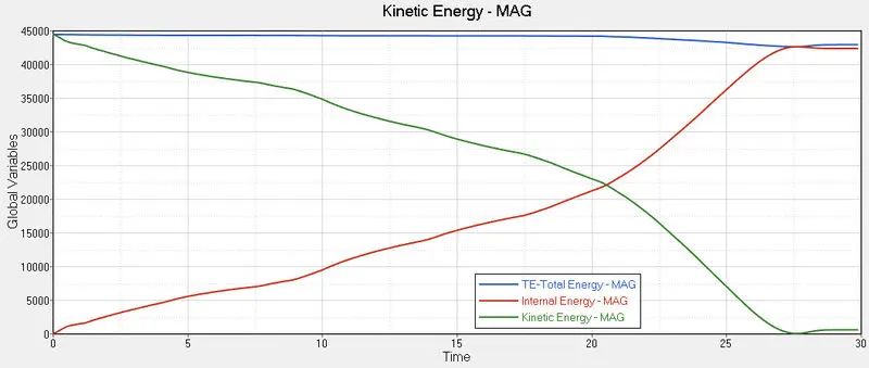 FIG. 23. KINETIC ENERGY.
- From fig. 23. there is significant drop in kinetic energy. This happens due to removal of notches.
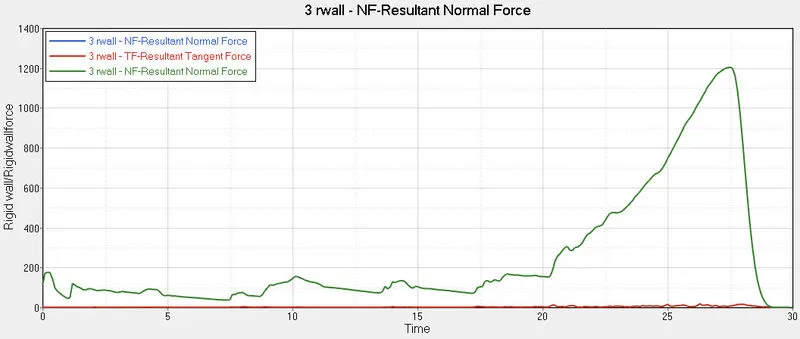 FIG. 24. RESULTANT FORCES.
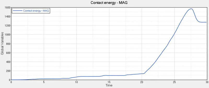 FIG. 25. CONTACT FORCES.
- From fig, 25. there is less amount of contact energy generated as compare to earlier cases. This occurs due to the notches removal, which results in less frictional forces during deformation.
CASE 5: Create a new notch in the middle ,select the whole section and run.
- Now, the crash tube model is further edited into a new notch in the middle. Element offset is used to create notch, which results in offset element at a distance.
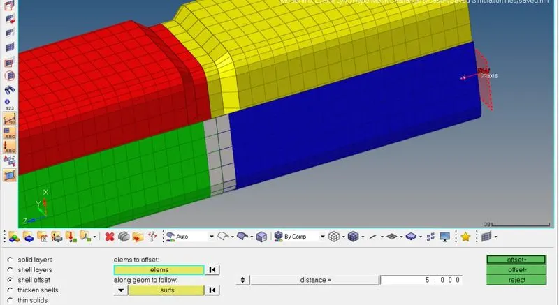 FIG. 26. ELEMENT OFFSET.
- The middle section of crash tube is selected & offset is created.
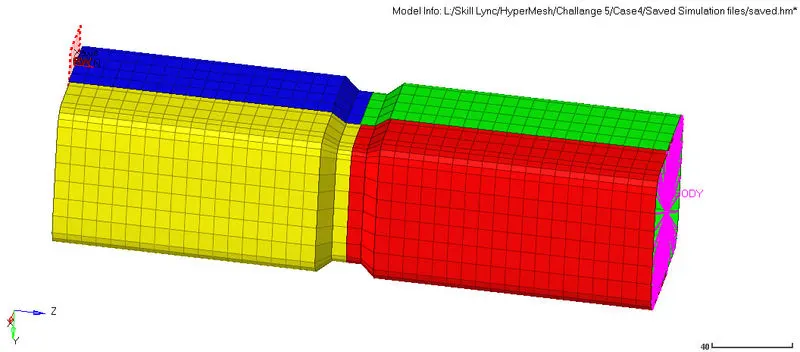 FIG. 27. MIDDLE NOTCH.
- The Radioss file is run, simulation went through. Results are as follows,
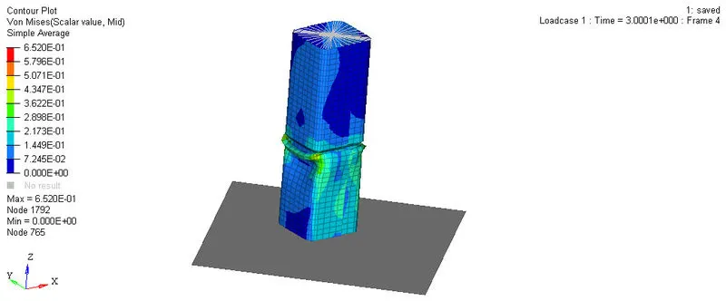 FIG. 28. STRESS VALUES.
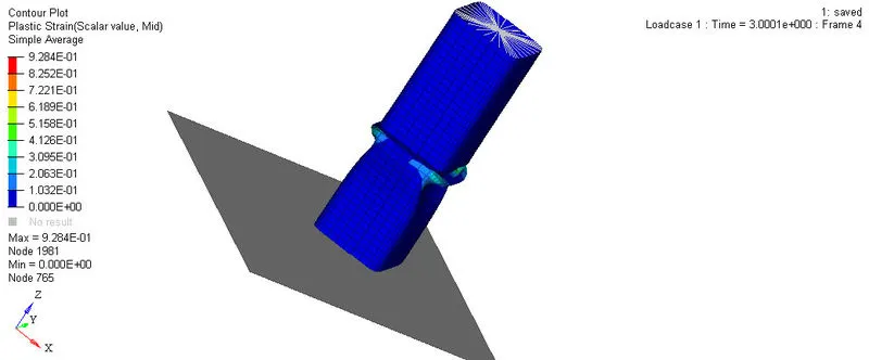 FIG. 29. STRAIN VALUES.
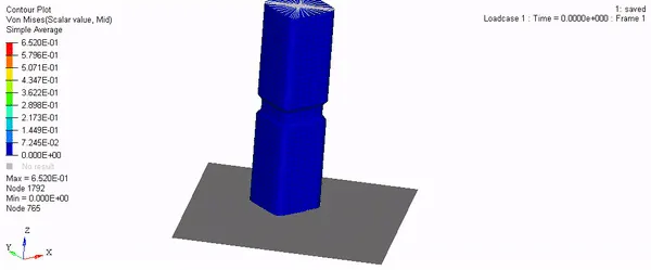
- The middle notch resulted in buckling effect at middle of crash tube.
- Out file values are as follows,
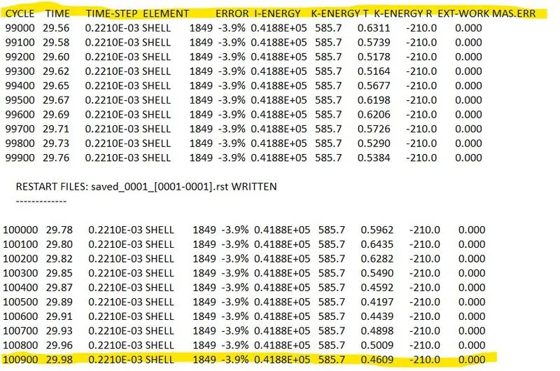 FIG. 30. OBTAINED VALUES.
- Switch to hypergraph we are able to plots various energies & forces as follows.
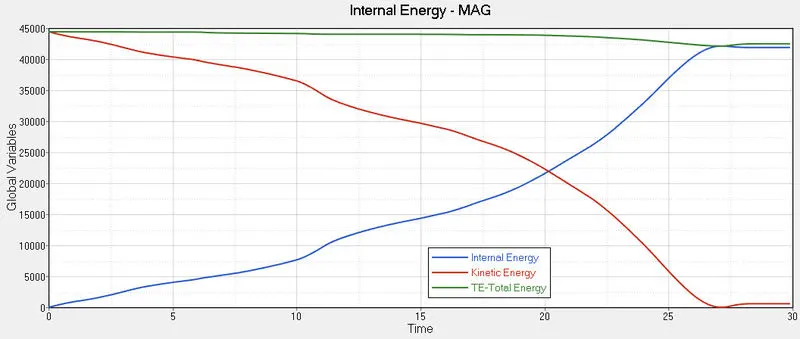 FIG. 30. ENERGY GRAPHS.
- From fig 30, there is significant drop in kinetic energy as a result of notch created in middle.
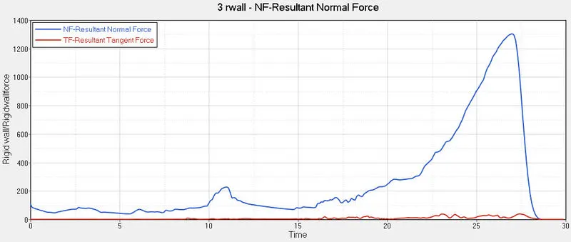 FIG. 31. RESULTANT FORCES.
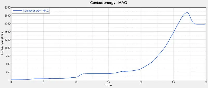 FIG. 32. CONTACT ENERGY.
- There is slightly rise in contact energy as a result of middle notch. The deformation tends to slightly increse it.
CASE 6: Create a new notch with nodes only from opposing 2 faces and run.
- We begin by making the notches only for opposing 2 faces.
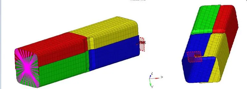 FIG. 33. NOTCH WITH NODE ONLY FROM OPPOSING FACES.
- The Radioss file is run, simulation went through. Results are as follows,
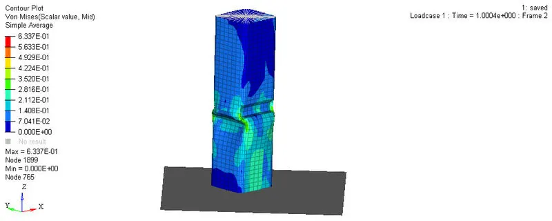 8FIG. 34. STRESS VALUES.
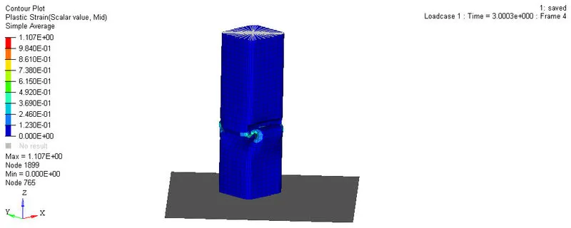 FIG. 35. STRAIN VALUES.
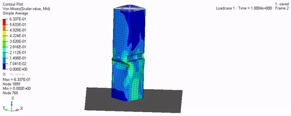
 FIG. 36. OUTPUT FILE VALUES
- Here, again the deformation has occur at the notches. It'sresult due to stress concentration. Also the faces opposite to notches went deform inward.
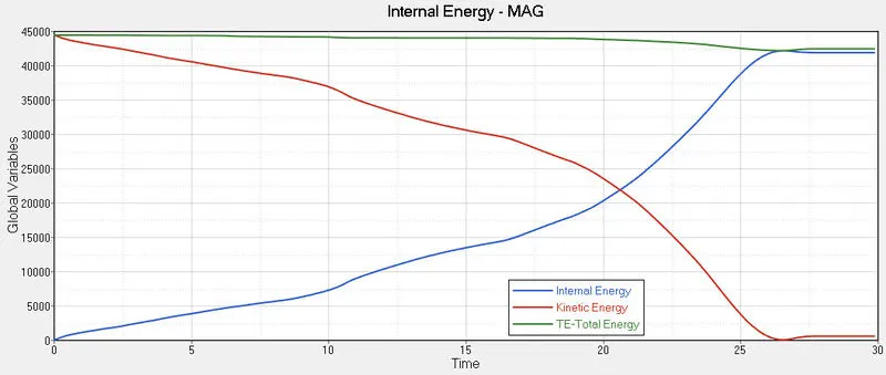 FIG. 37. ENERGIES GRAPH.
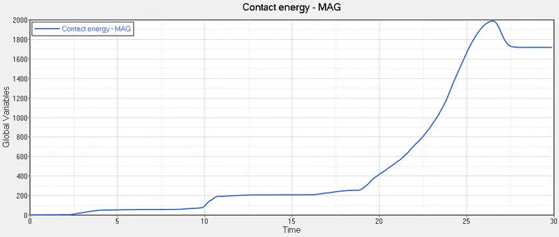 FIG. 38. CONTACT ENERGY.
- Here, the contact forces is less than all previous cases.
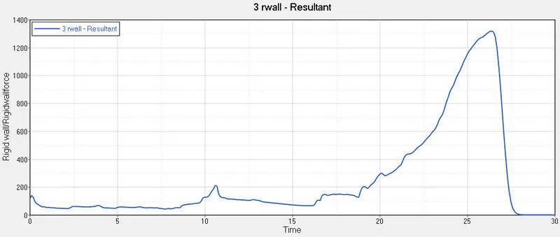 FIG. 39. RESULTANT FORCES.
RESULTS:
| CASE NO. | TOTAL NO. OF CYCLE | TIME-STEP VALUE | ENERGY ERROR% | INTERNAL ENERGY | KINETIC ENERGY |
| 1 | 83700 | 0.2427E-03 | -3.8% | 0.4201E+05 | 593 |
| 2 | 83700 | 0.2427E-03 | -3.8% | 0.4201E+05 | 593.2 |
| 3 | 96000 | 0.2643E-03 | 0% | 0.4372E+05 | 508.8 |
| 4 | 78000 | 0.2445E-03 | 3.0% | 0.4233E+05 | 560 |
| 5 | 100900 | 0.2210E-03 | -3.9% | 0.4188E+05 | 585 |
| 6 | 82800 | 0.2706E-03 | -0.4% | 0.4186EE+05 | 546.8 |
CONCLUSIONS:
- For first two cases type 7 interface is used followed by assigning type 11, which resulted in stable simulation. The simulation went through, results in buckling & the slave nodes tries to penetrate master segments.
- Second case was no different but with slightly more simulation time due to introduction of Inacti6 formulation.It checks initial penetrations.
- Third case result in greater kinetic enery due to assigning type 7 interface.
- Fourth case follows a less energy graph due to removal of boundary conditions.
- Meanwhile, fifth case result in greater enery error due to introduction of notches at middle.
- Finally sixth case followed a reduction in energyerror as result of notches creates only at opposing faces.