Assignment 5-RADIOSS Interfaces & Study of Effect of Notches Challenge
OBJECTIVE:
- Create the mesh for bumper assembly, mesh size should be 6mm.
- Run the crash tube model as it is.
- Change the Inacti = 6 and run.
- Create the type 11 contact and run.
- Remove both notches and remove boundary condition on rigid body node then run.
- Create a new notch in the middle, select the whole section and run.
- Create a new notch with nodes only from opposing 2 faces and run.
- Plot RWALL forces, contact forces, internal energy and Create TH/PART for all parts and compare results for all cases.
- Comment your thoughts on why there is a change in the internal energies.
- How does the notch affect the results?
- Plot energies and note any difference.
SOLUTION:
Meshing of Bumper Assembly:
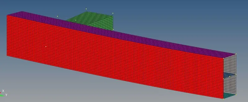
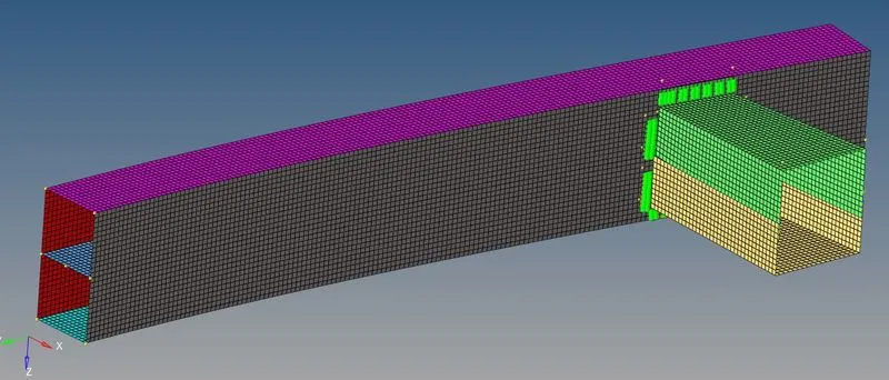
The aim is to mesh the given model of bumper assembly using a mesh size of 6mm. This can be done using automesh option in the 2D panel. The size can be set as 6mm and the element type can be used as mixed type. Since the given geometry has mostly rectangular plates, a very good mesh can be obtained by controlling the number of nodes on either end of the plates. Once the meshing is done, it’s important to check the mesh connectivity. For ensuring the same, edges option in the tool option can be used to identify free edges and correct mesh accordingly. Finally, the upper and lower crash boxes are joined to the bumper beam using appropriate connectors.
Crash Analysis of given model:
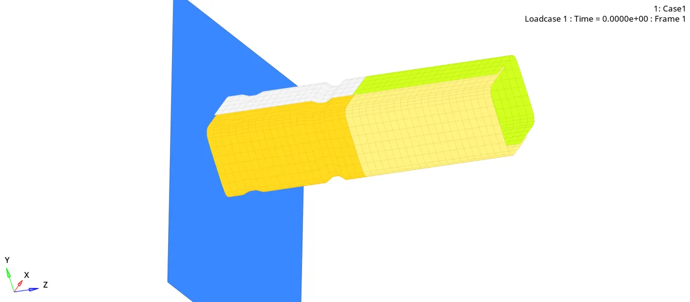
The aim is to perform crash analysis of the given model under 6 different conditions. In case 1, the model is solved as given. In case 2, the value for Inacti is changed to 6 in the previous model and solved. For case 3, type 11 contact is created for the model and it is solved. In the next case, the notches and boundary conditions in the given model is removed and solved. In case 5, notches are created at the middle section and in the final case notches are created only on two opposite surfaces and run.
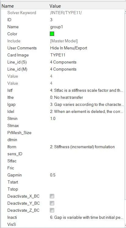
To change the Inacti value, go to solver tab → open Inter card → set value for Inacti. For creating type 11 contact, go to solver tab → right click Inter card → insert type 11 → set parameters as shown in figure.
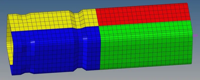
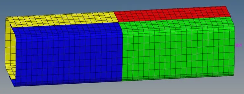
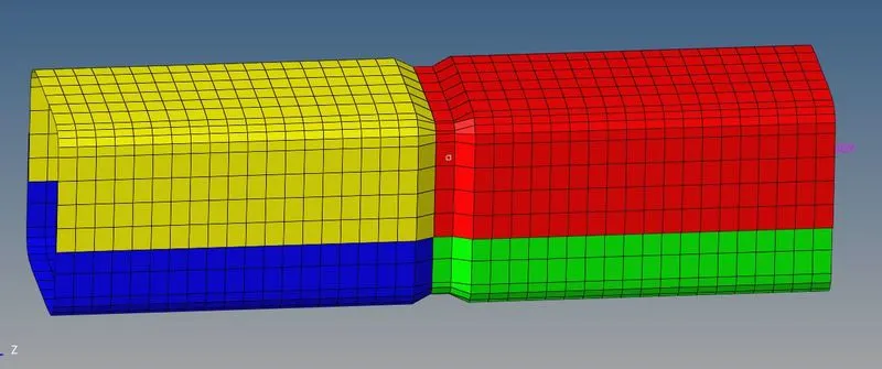
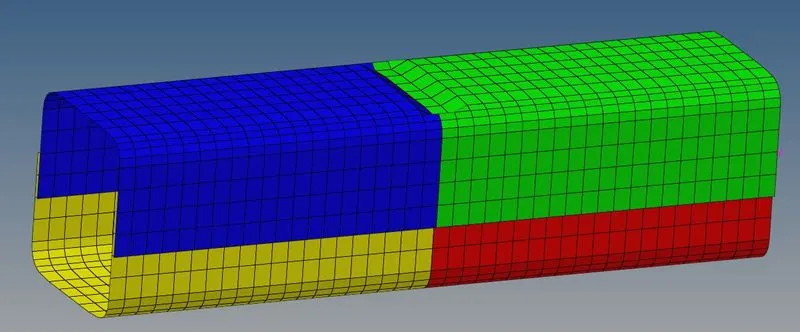
For removing notches, align option in the node edit panel can be used. Geom → node edit → align node → select reference nodes → select nodes to be aligned. For creating notches, use translate option from tools tab.
 5
5
Cases and Simulations:
Case 1:
Case 2:
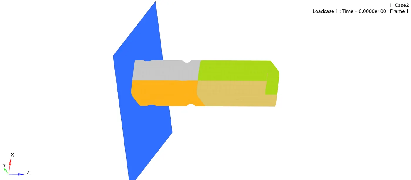
Case 3:
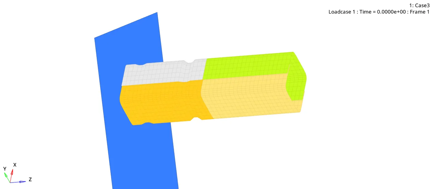
Case 4:
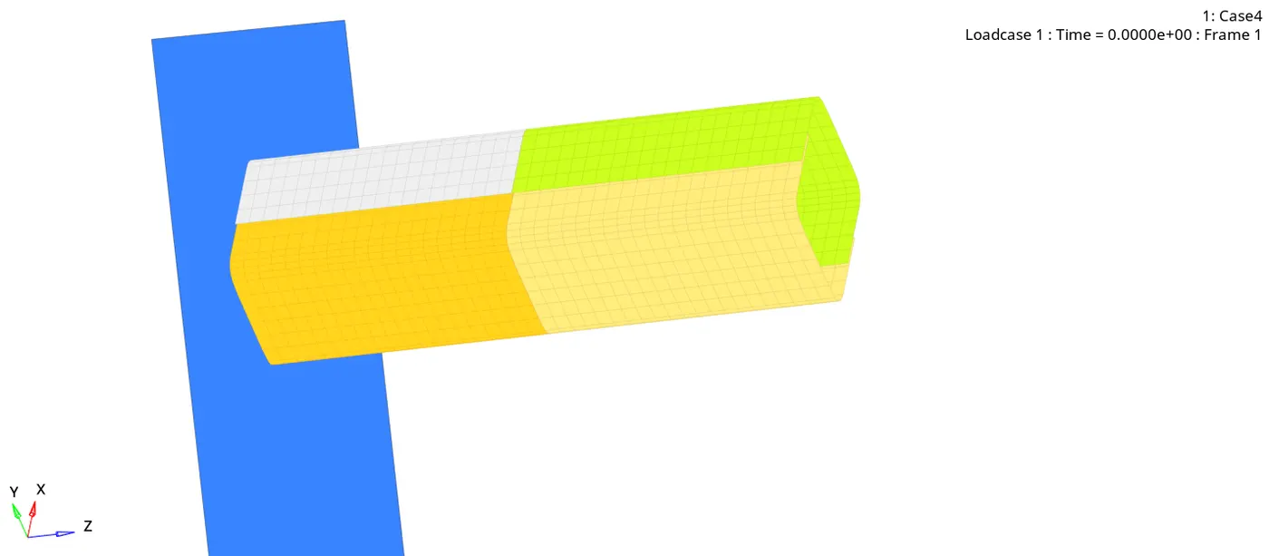
Case 5:
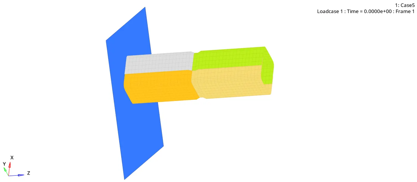
Case 6:
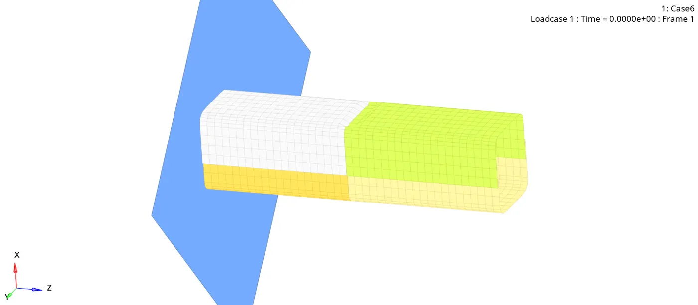
Results and Observations:
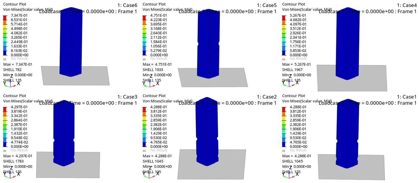
Case 1:
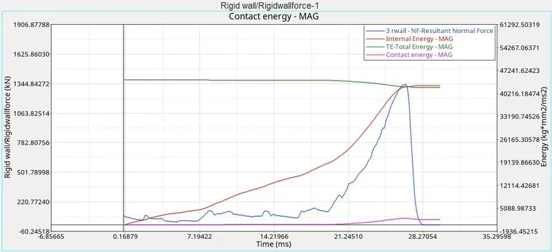
Case 2:
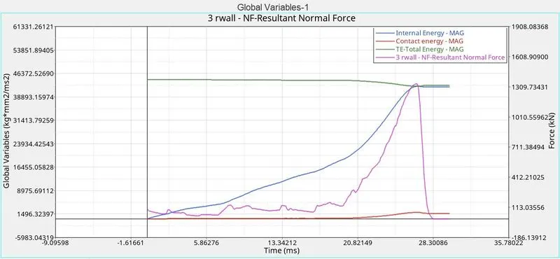
Case 3:
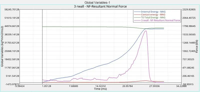
Case 4:
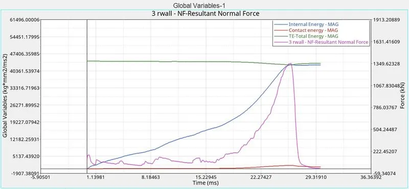
Case 5:
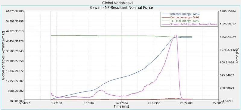
Case 6:
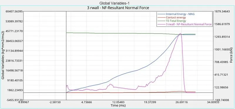
Comparison of Internal Energies & Contact Energies:
Case 1 to 6 is represented by lines given in the legend from top to bottom.
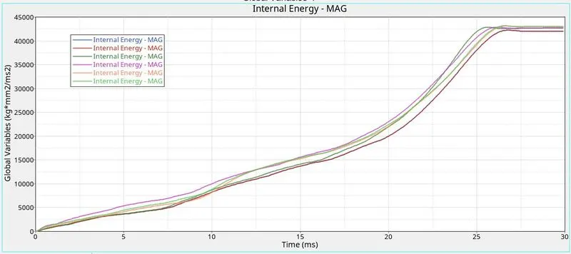
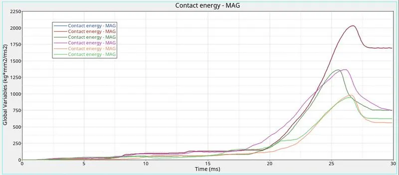
From the above plots, it can be observed that there is not much difference between the internal energies generated in different cases. But in general, it can be concluded that the presence of notches will create more stress concentration along these regions and higher deforamtion is observed along these regions. Majority of the crashing of the model happens from time = 0 to 26. It can be observed that over this period, the internal energy is largest in case 4, ie in the model without any notches. This means that the presence of notches helps in preventing internal energy build up in the model. The contact energy is found to be the least in cases 5 & 6 and maximum for cases 1 & 2.