Assignment 5-RADIOSS Interfaces & Study of Effect of Notches Challenge
Aim: To Create the mesh for bumper assembly, mesh size should be 6mm and simulate the given model with seven different cases in radios as per problem statement and compare it using various plots.
Problem statement :
Questions:
. Create the mesh for bumper assembly,mesh size should be 6mm.
1. Run the crash tube model as it is.
2. Change the Inacti-6 and run.
3. Create the type 11 contact and run.
4. Remove both notches and remove boundary condition on rigid body node then run.
5. Create a new notch in the middle select the whole section and run.
6. Create a new notch with nodes only from opposing 2 faces and run.
Note:
. Plot RWALL forces, contact forces, internal energy and Create TH/PART for all parts and compare results for all cases.
• Comment your thought on why there is a change in the internal energies.
How does the notch affect the results?
• Plot energies and note any difference.
Solution :
Model 1:- Meshing of bumper assembly
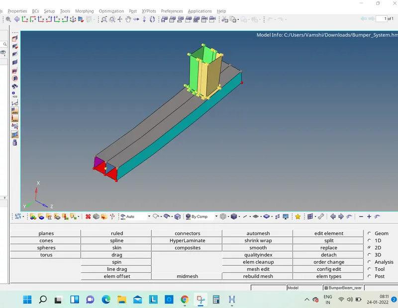
1. Import given model into hypermesh
• To Open the .hm file, Go to the File menu in the Standard menu bar>> Click Open >> Click Model >> Select the model to open >> click
• The model is displayed in the Graphics Area.
2. Assign quality parameters :
• To give the Criteria, Click on the Preferences in the Standard Menu bar >> Click Criteria Menu Settings >> Give Target Element Length as 6mm >> Click Ok.
. The Criteria are given.
3. Meshing :
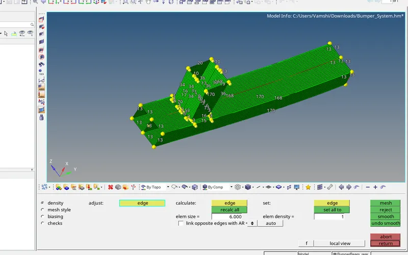
• To perform a mesh, Select Auto mesh option from the 2D panel >> Click the Surface to mesh >> Give the Element size as 6 >> Click mesh.
4. Giving proper connections:
a. Now we have create a connection between the crash box and rear bumper. So go to connectors - seam and provide the necessary
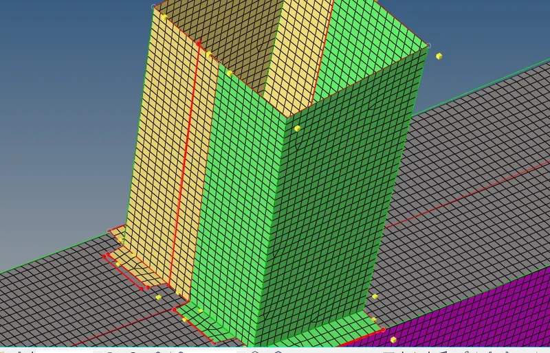
b. we have to connect the crash box and rear bumper, so as to give accurate result when we perform the analysis. There are different types of connections are available, apart from this we have chosen materials. The below diagram shows the seam connection between the crash box and rear bumper.
seam weld which is used to connect the two different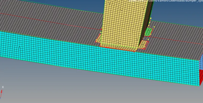
Model 2:-Solving different cases on crash tube
Case 1. Run the crash tube model as it is.
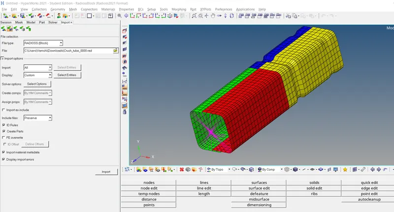
• After the Model is imported, The Simulation needs to be performed without changes in model in this case.
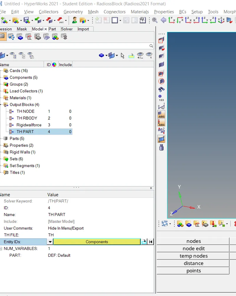
In order to create the THPART we have to click on the output Blocks and create the TH PART. in entity id instead of nodes keep components and select all four components and click on ok. Then the TH part is created.
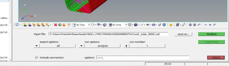
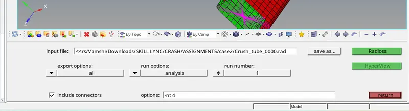
• To simulate the model, Go to the Analysis tab, Select the Radioss option> Select the location to save the file > Check include collectors box> In the options tab, type "-nt 4"> Click Radioss.
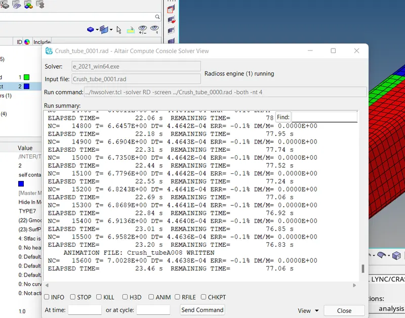
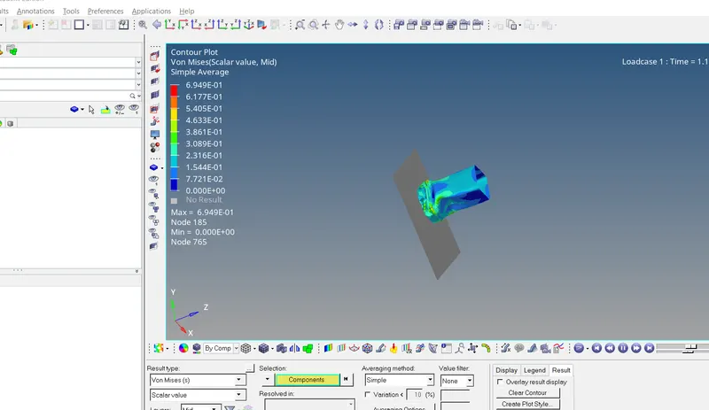
Open hyperview to view animation and contour plots from H3d file
Open hypergraph 2d for observing the energy plot data from TAO1 file.
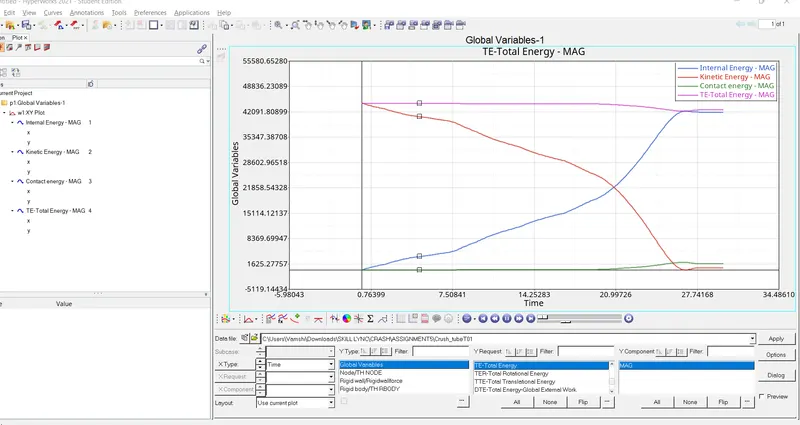
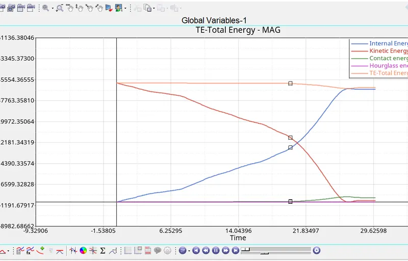
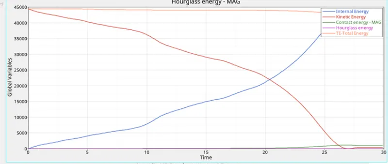
As seen in the graph, the kinetic energy is maximum at the beginning which starts decreasing once the crush tube impacts the rigid wall. This energy is converted into strain energy as the crush tube deforms
as observed by the increase in internal energy of the system. Energy error is about -3.8% which is acceptable. A part of total energy is used by the contact energy as seen in the graph. As total energy
reduces, contact energy increases. Contact energy contact force distance moved to avoid penetration. The contact force is basically the energy spent by enabling a contact force to avoid penetration. This
should be minimum. As seen above, the contact energy is very less for most of the time and there is slight increase in the contact energy at the end of simulation.
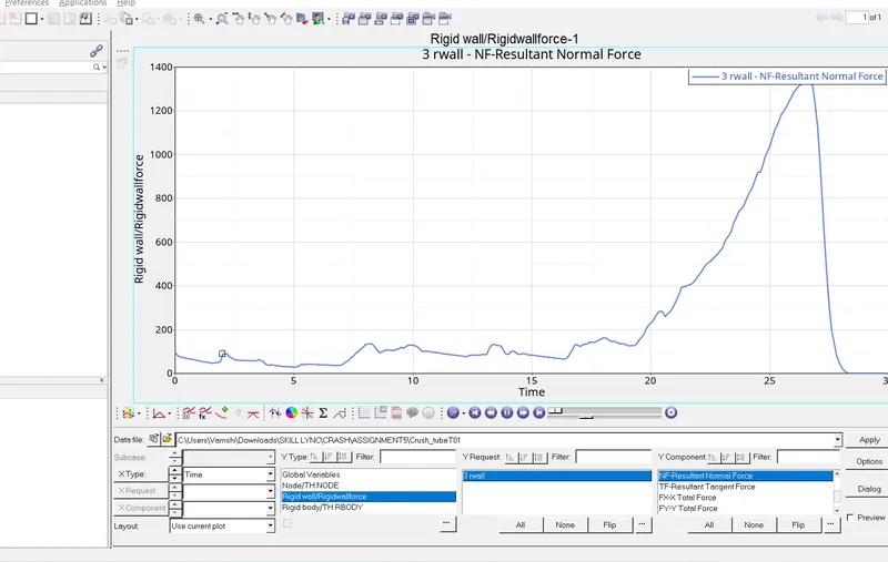
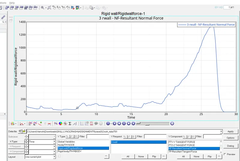
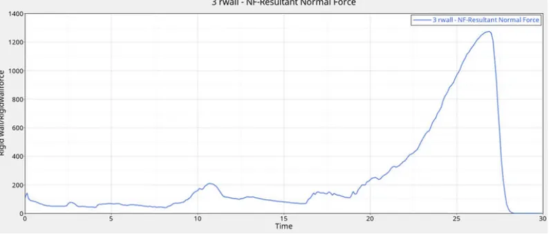
For rigid wall, there is sudden rise in the peak value of rigid wall force after T-25. By this time, the crush tube is completly crushed and therefore the deformed model having no further scope for deformation
gets pushed against the wall with some velocity to which the rigid wall reacts.
. Case 2:
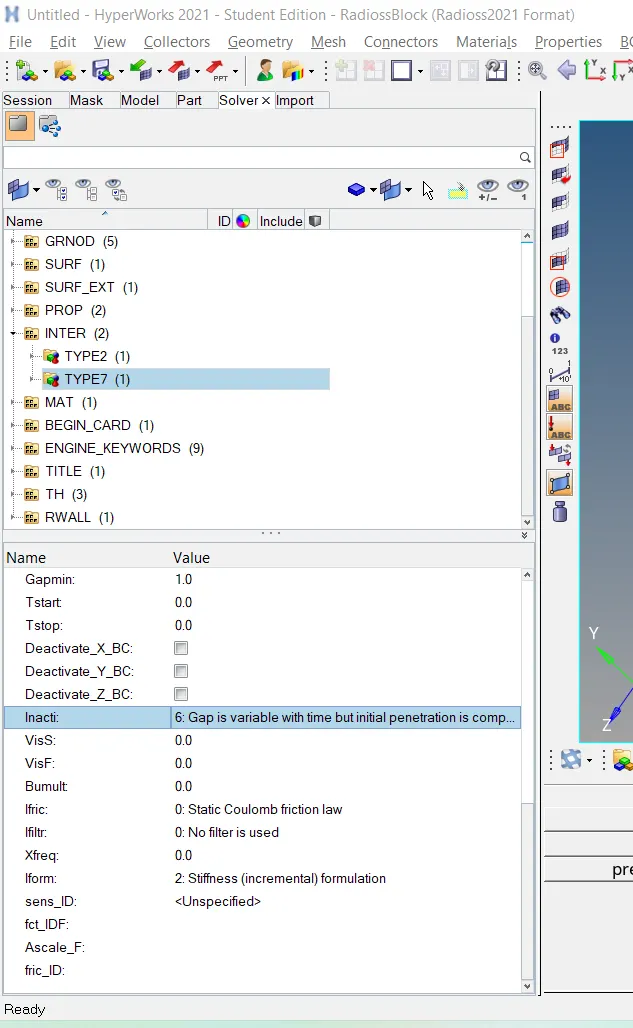
In this case, we have to change the Inact = 0 to Inacti=6. Inacti = 6 will remove any initial penetration present.
• To simulate the model, Go to the Analysis tab, Select the Radioss option> Select the location to save the file > Check include collectors box> In the options tab, type "-nt 4"> Click Radioss.
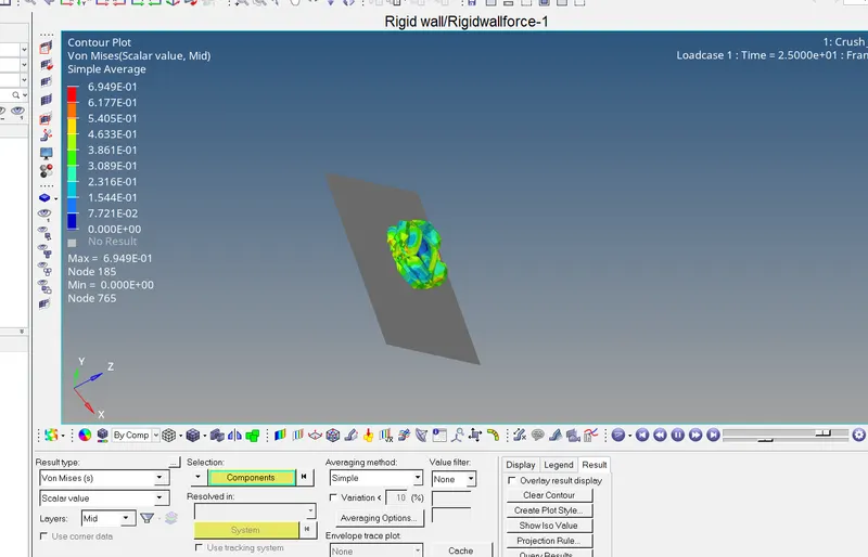
Open hyperview to view animation and contour plots from H3d file
Open hypergraph 2d for observing the energy plot data from TAO1 file.
The nature of deformation and the energy graph are similiar in nature compared to case 1.
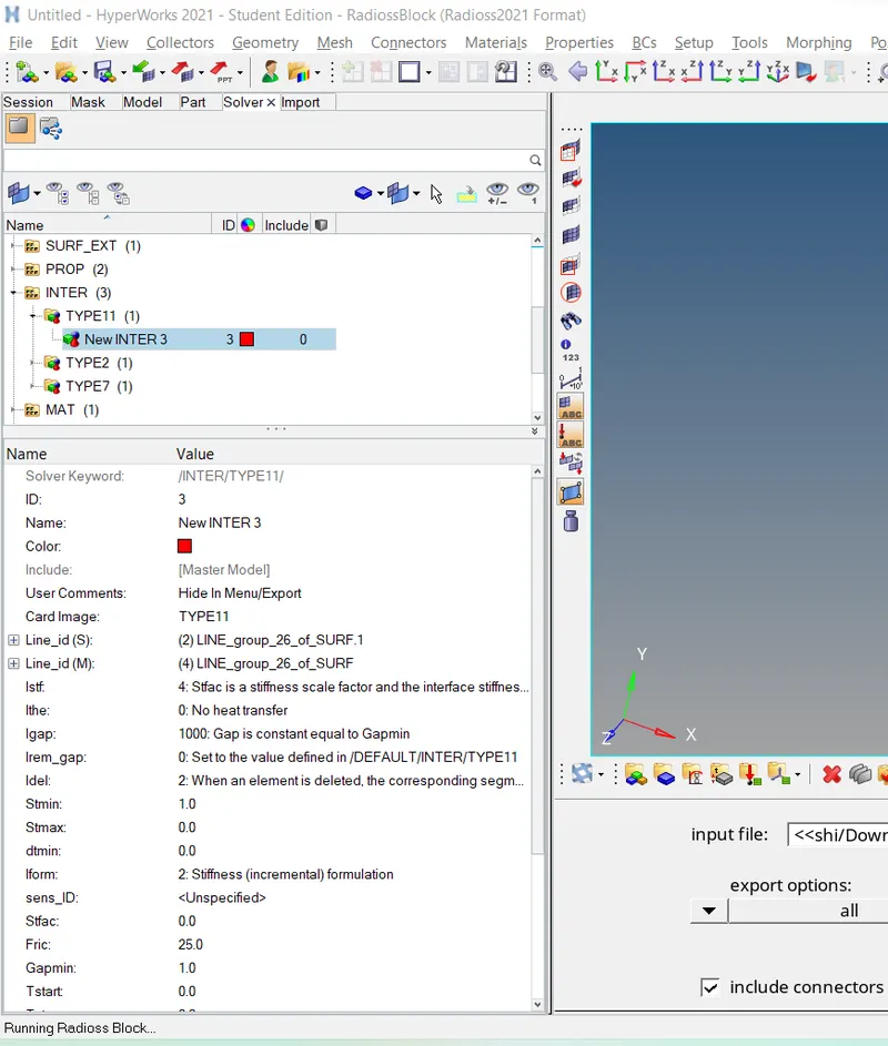
Case 3:- Create the type 11 contact and run.
• In this case, the model is imported and run the simulation with recommended properties whereas we have to change Card image as Type 11 contact as per problem statement.
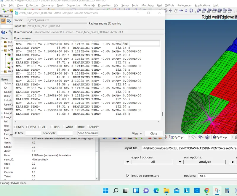
• To simulate the model, Go to the Analysis tab, Select the Radioss option> Select the location to save the file > Check include collectors box> In the options tab, type "-nt 4"> Click Radioss.
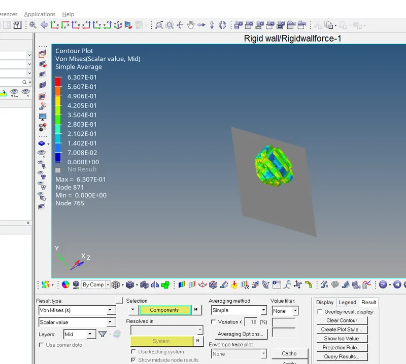
Open hyperview to view animation and contour plots from H3d file
Open hypergraph 2d for observing the energy plot data from TAO1 file.
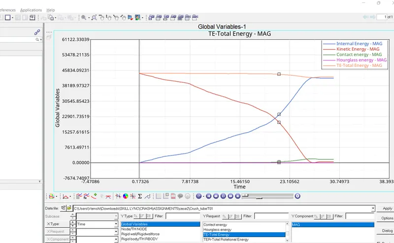
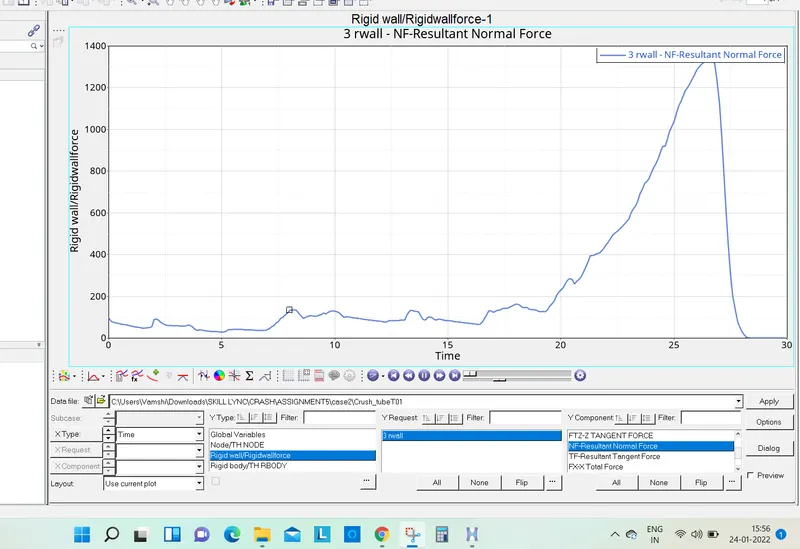
Here too, the nature of deformation and energy graph nature are similiar as previous case.
Case 4:
Here, we have to remove both the notches and the boundary conditions on the rigid body and run the simulation. To remove the notches, we can use align option from the node edit option available under
Geom page. Go to Geom> node edit > align. In the 1st and 2nd end selector, select two nodes (black) respectively, which will define a line along which the selected nodes on the notch (white) will be placed,
thus removing the notch. Click on align. The nodes will be aligned as seen below. Repeat the same procedure for the entire notch.
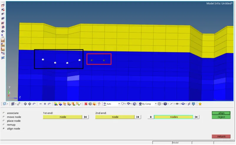
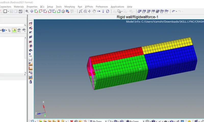
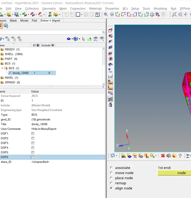
To remove the boundary conditions on the rigid body, go to Solver > BCS BCSrbody_12456. Uncheck DOF1, DOF2, DOF3, DOF4. DOF5, DOF6 which will allow translation in X, Y, Z and rotation in X, Y, Z
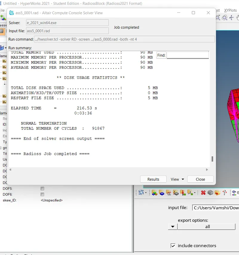
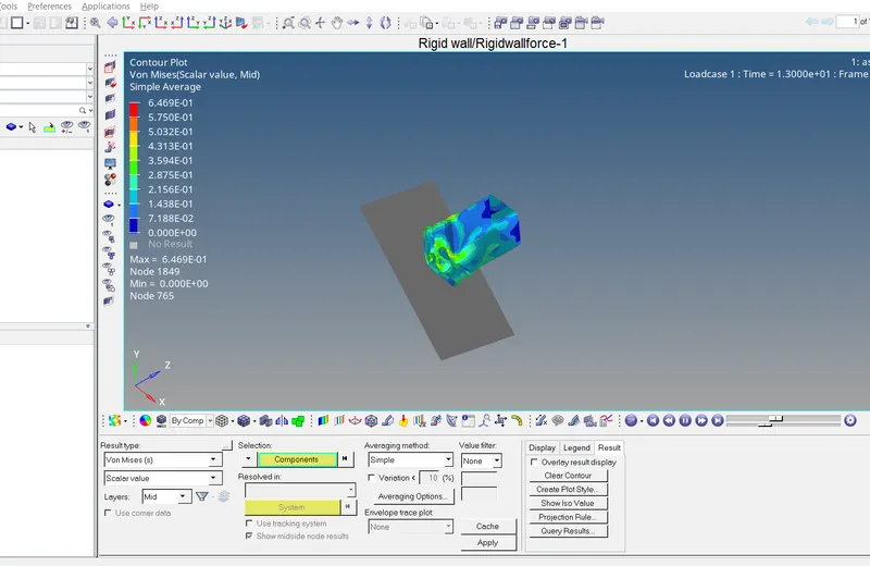
Open hyperview to view animation and contour plots from H3d file
Open hypergraph 2d for observing the energy plot data from TAO1 file.
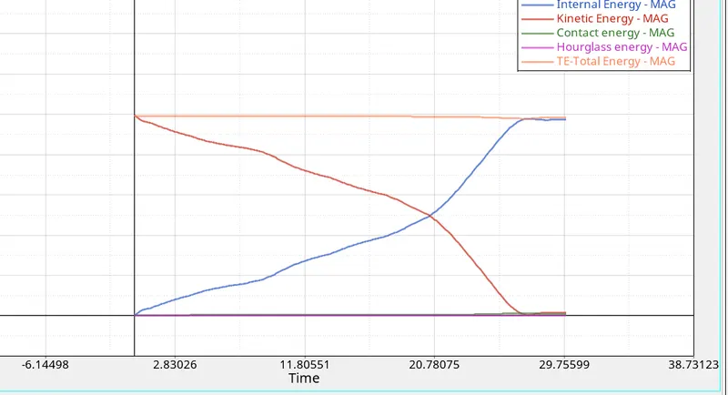
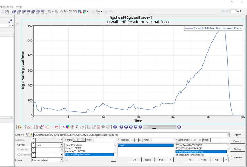
As seen here, there no notches on the crush tube. During impact, there is no localized deformation as there are no notches present and the deformation progresses as expected.
Case 5:
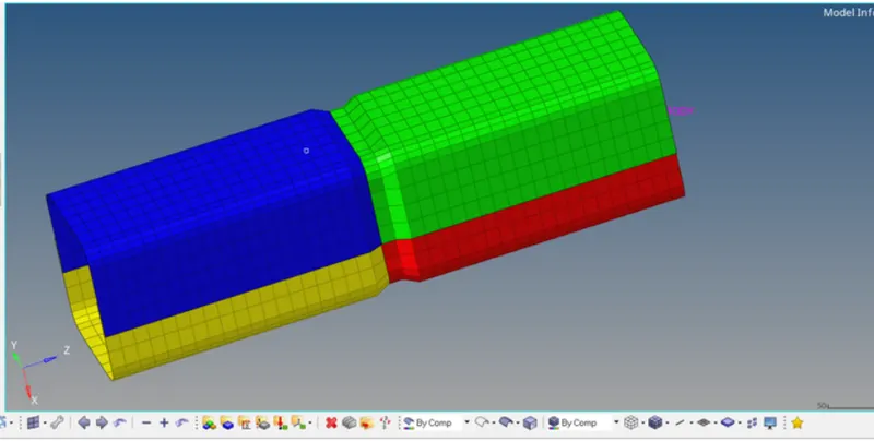
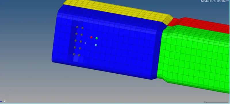
In this case, we have to create a new notch in the centre and run the simulation. We can create notch by using translate option available under Tool page. To properly create the notch, use the N1,N2,N3
 .
.
The nature of deformation and the energy graph are similiar in nature compared to previous cases.
Case 6:
Create notches on two opposing surfaces and run the simulation. The procedure to create notch is the same as discussed earlier using Translate tool
RESULTS
The change in the internal energy is due to the notch. With the removal of the notch, the internal energy decreases and hence reduces the energy error as well.
. The notch areas have high stresses and deform first. In the plane surface where the notches are removed the stress levels are low. Hence, we can state that by removing the notch helps to reduce the stress acting in the body.
• 3mm shell is requires higher internal energy; it means ability to absorb force is higher in shell with 3mm thickness compared to shell with 2mm thickness. More thickness of shell has more internal energy the component.