Assignment 5-RADIOSS Interfaces & Study of Effect of Notches Challenge
AIM:- TO CREATE THE MESH FOR BUMPER ASSEMBLY AND SIMULATE THE GIVEN MODEL WITH SIX DIFFERENT CASES IN RADIOS AS PER PROBLEM STATEMENT AND COMPARE IT USING VARIOUS PLOTS.
Questions:
- Create the mesh for bumper assembly,mesh size should be 6mm.
- Run the crash tube model as it is.
- Change the Inacti=6 and run.
- Create the type 11 contact and run.
- Remove both notches and remove boundary condition on rigid body node then run.
- Create a new notch in the middle ,select the whole section and run.
- Create a new notch with nodes only from opposing 2 faces and run.
Note:
- Plot RWALL forces ,contact forces,internal energy and Create TH/PART for all parts and compare results for all cases.
- Comment your thought on why there is a change in the internal energies.
- How does the notch affect the results?
- Plot energies and note any difference.
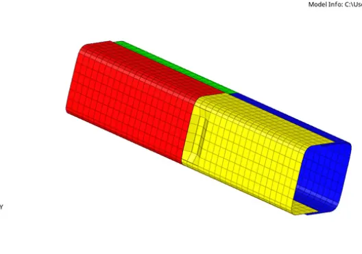
MODEL-1:-Create the mesh for bumper assembly,mesh size should be 6mm.
- First import bumper geometry and then geometry clean-up.
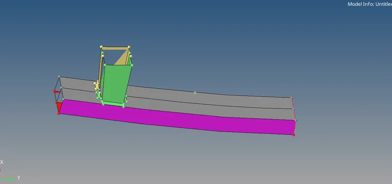
- Geometry clean-up is done.
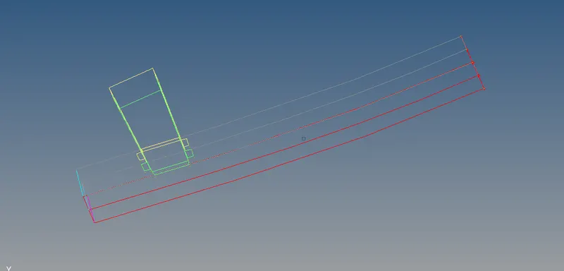
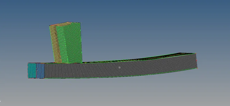
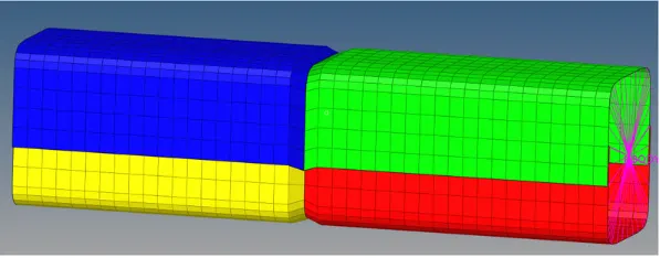
- Meshing is done with mesh size 6mm and mesh type mixed.
- Reflect geometry to make complete .
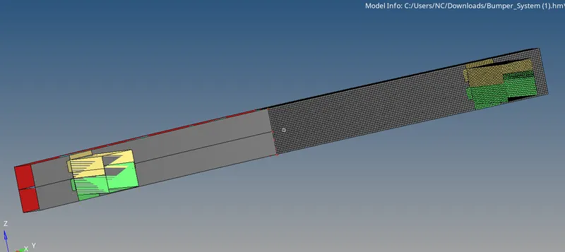
MODEL-2:- SOLVING DIFFERENT CASES ON CRASH TUBE.
CASE-1: Run the crash tube model as it is.
- First import the model.
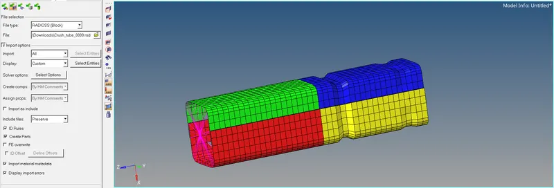
- After imported the model, the simulation needs to be perfomed without any changes.
- To simulate the model, go to the Analysis tab select the Radioss option>select the location to save the file>check include collectors box> in the option tab type -nt 4> click Radioss.

- After that, open Hyperview to see animation and contour plots from h3d file.
- On competion of the simulation, a pop up window open and showing the run summery.
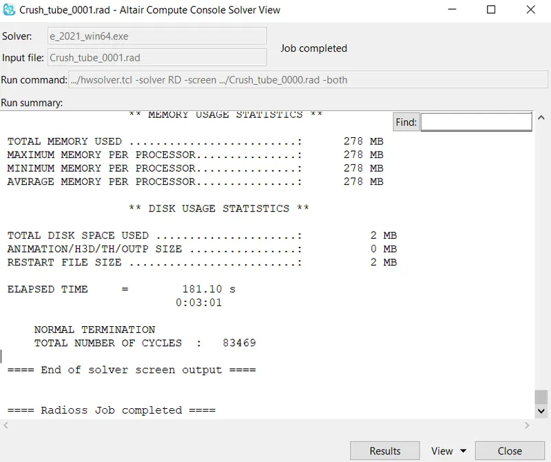
- Open output filr and check energy error and mass error.
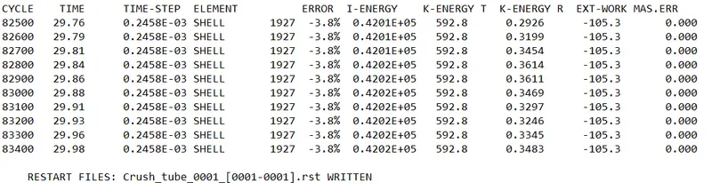
- From the output file energy error is -3.8% and mass error is 0% which is less than -15% to 2% and 1% respectively, so we can accept the results and plot the graph by using Hypergraph.
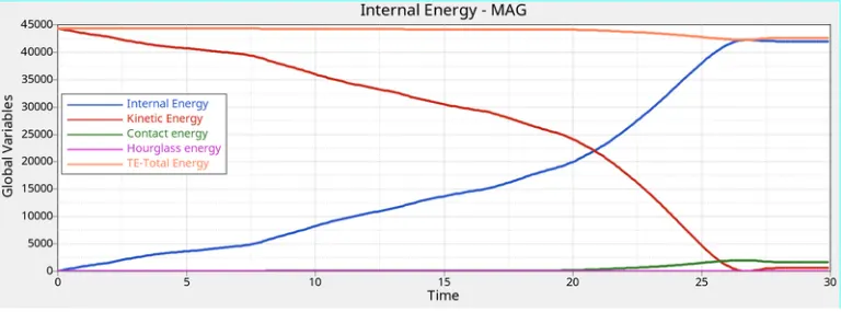
- Internal energy keeps increasing because the tube continously absorbs energy while crushing on to the rigid wall, which result in deformation. The internal energy goes constant.
- Kinetic energy keeps decreasing due to the initial vlocity on the tube. The curve starts from high values and deacreasing to low due to the deformation. There is a slighlty increase afterwork due to rebound after deformation.
- Contact energy is a type of energy that is created when one element constant neighboring elements. The opposing force created by the element is called contact energy. There is no contact in the initial stage, so that's why the graph goes constant. After some time, the graph slightly increase due the buckling of elements. While the entire tube pressing on the rigid wall, the buckled elements are forced into contact.
- Total energy decreases at some point due to increasing of contact energy at the some time. So, the contact energy affects the total energy.
- Hourglass energy is constant due to the presence of recommended properties.
RIGID WALL RESULTANT FORCE GRAPH-
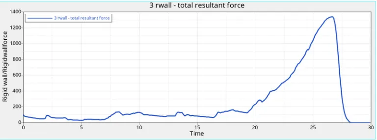
- It is evident that the rigid wall experiences some forces suddenly, due to the crush tube over the rigid wall and absorb the energy form crush tube after the deformation completes, the rigid wall force is decreased immediately due the energy trasferred completely.
CASE-2: Change the Inacti=6 and run.
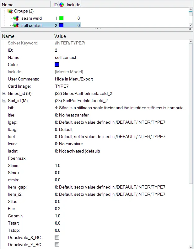
- In this case, the model is imported and run the simulation with recommended properties whereas we have to change Inacti = 6 as per problm statement. The 7 contact interface is used with recommended property as shown in below image-
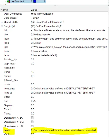
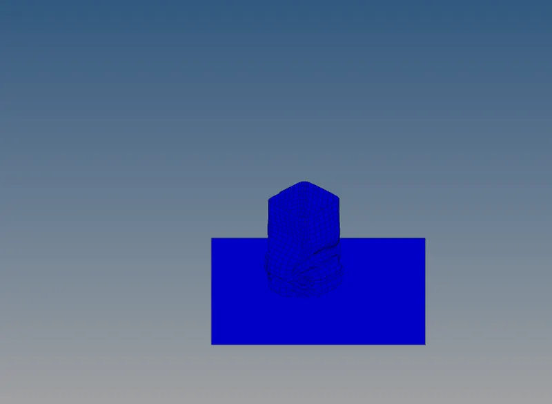
- After changing the recommended parameters run the simulation with the same step to be carried as per previous case.
- On competion of the simulation, a pop up window open and showing the run summery.
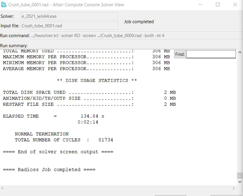
- Open output filr and check energy error and mass error.
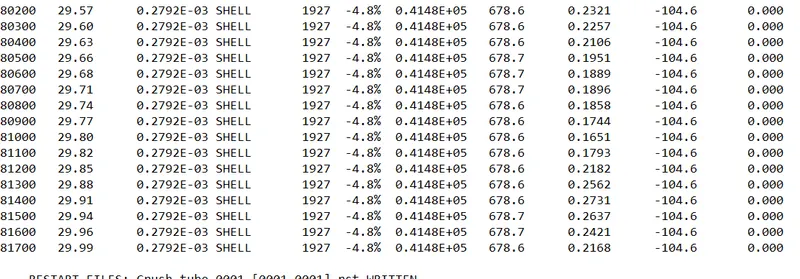
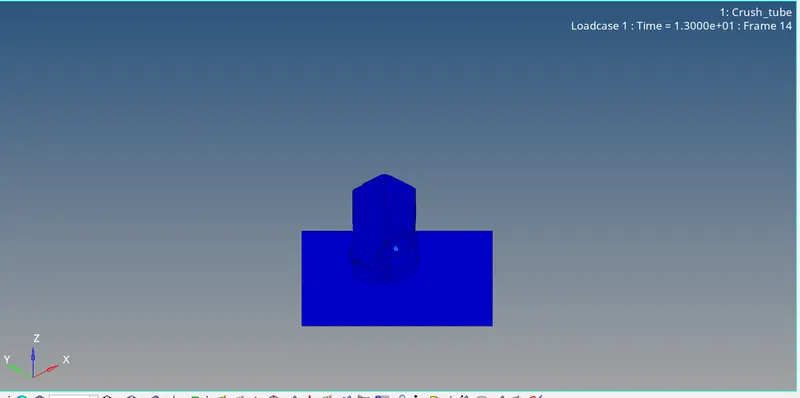
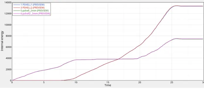
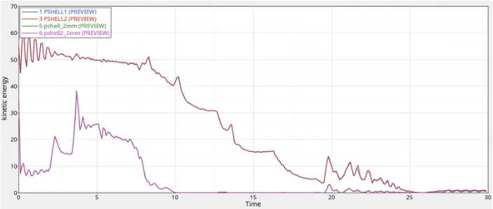
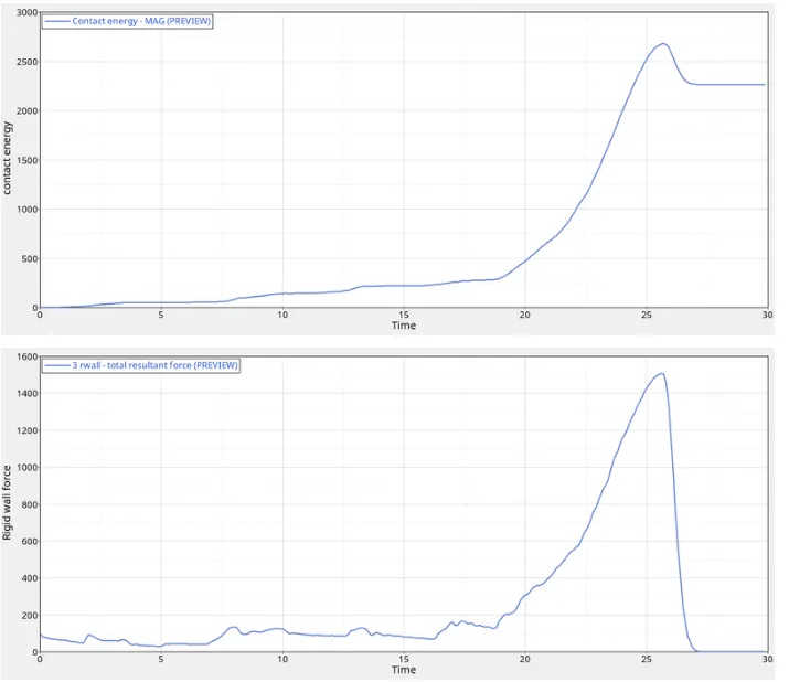
- For the simulation, the max von mises stress is created as 69.53NNmm2 and the max contact force is created as 3N where as the time history fr all the components are created in order to study the deformation and energy variation in each components with respect to time.
- The internal energy for the p_shell_2.0 components is increasing at the begning because it is attached to the rigid wall and deform smoothly from the notch area where as the stiffness is less at this part. The interal energy for the o componenetsis zero for 10ms and linearly increasing to deform at a velocity 13.3m/s and the stiffness is high for this part because of flat surface area.
- The kinetic energy for the p_shell_2.0 components is varying at the begning fo the 10ms and maintained constant which means no more deformation occures because of notch area presents over the components deforms very quickly. The kinetic energy for the p_shell_3.0 components is continuously varying over the time 25ms means deformation takes place at a velocity of 13.3 m/s.
- The contact energy is varying at a very small amount at the begning and there is a sudden peak formed because there is large amount of energy developed at the end of deformation. The overall elements are becoming overlapped or compressed which will develop large force on the rigid wall around 1500N and energy created 2.6KJ.
CASE-3: Create the type 11 contact and run.
- In this case, change the card image as Type 11 contact as per problem statement.
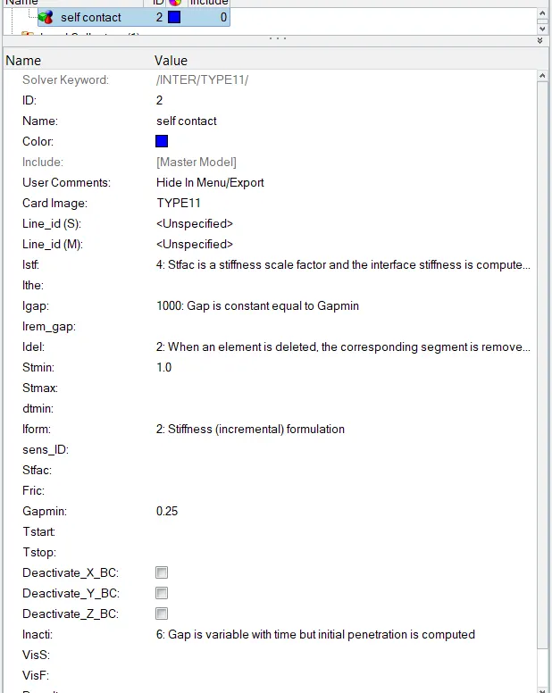
- Type 11 takes into the account of the connections made by the edges to master segment and hence improves the accuracy of the reactive force calculation.
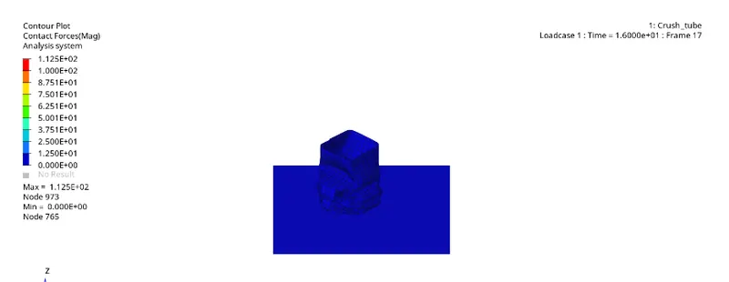
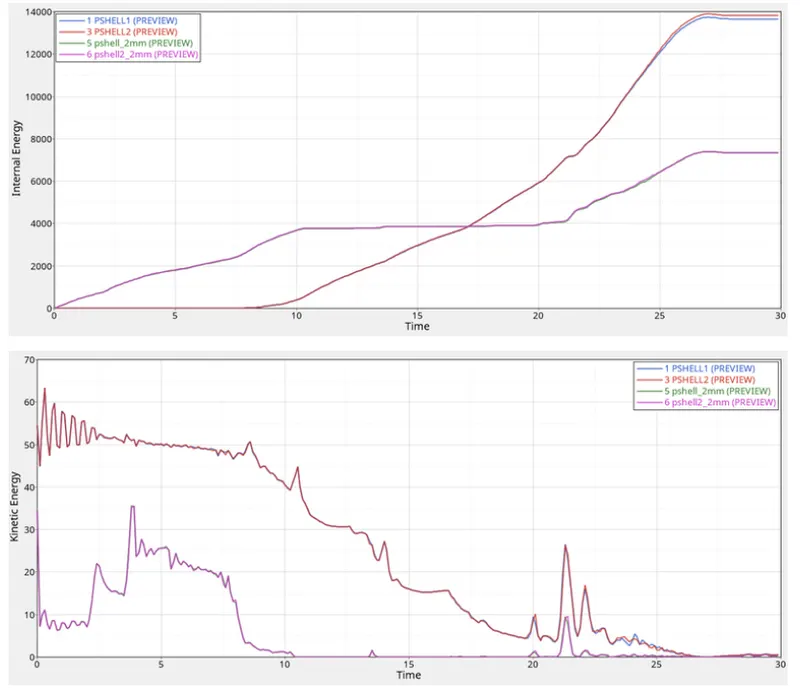
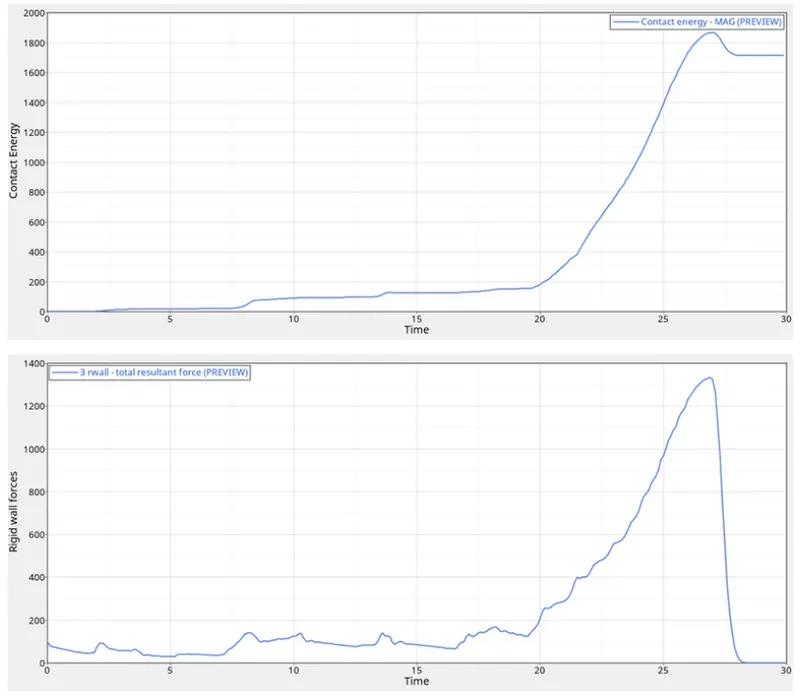
- For the simulation, the max contact force is created as 112.5N where as the time history fr all the components are created in order to study the deformation and energy variation in each components with respect to time.
- The internal energy for the2mm shell components is increasing at the begning because it is attached to the rigid wall and deform smoothly from the notch area where as the stiffness is less at this part. The interal energy for the 3mm shell componenets is zero for 10ms and linearly increasing to deform at a velocity 13.3m/s and the stiffness is high for this part because of flat surface area. The end of this components defined the rigidity with a translational (Z- direction) DOF.
- The kinetic energy for the 2mm shell components is varying at the begning fo the 10ms and maintained constant which means no more deformation occures because of notch area presents over the components deforms very quickly. The kinetic energy for the 3mm shell components is continuously varying over the time 25ms means deformation takes place at a velocity of 13.3 m/s.
- The contact energy is varying at a very small amount at the begning and there is a sudden peak formed because there is large amount of energy developed at the end of deformation. The overall elements are becoming overlapped or compressed which will develop large force on the rigid wall around 1300N and energy created 1.9KJ.
CASE-4: Remove both notches and remove boundary condition on rigid body node then run.
- Import the 000.rad file. Then remove all the notches present in the model using Align Option.
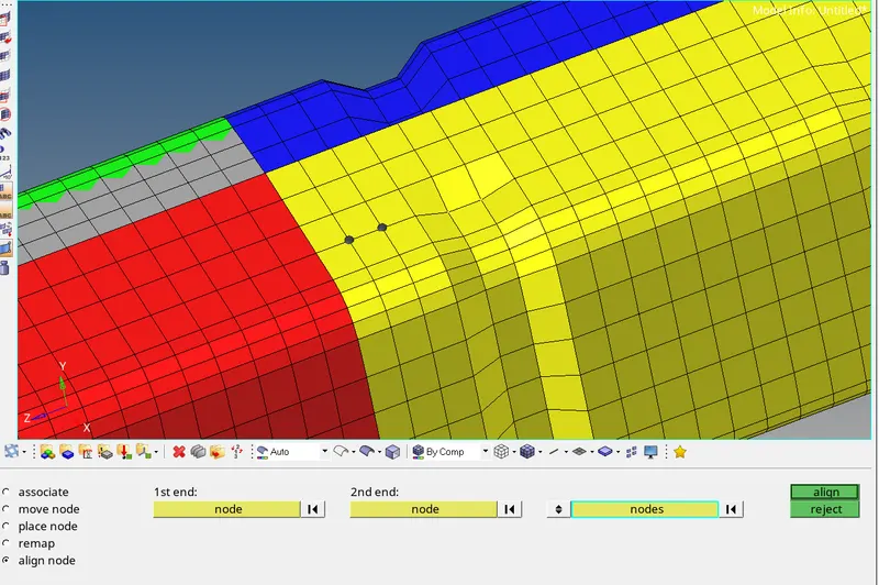
- All the notches are removed successfully.
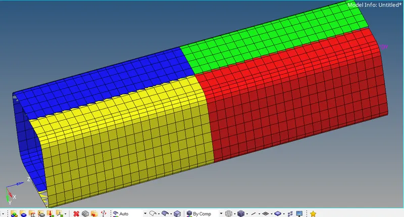
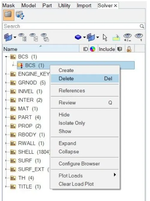
- Now delete the boundary condition go to solver deck< delete the BCS entity in the solver deck.
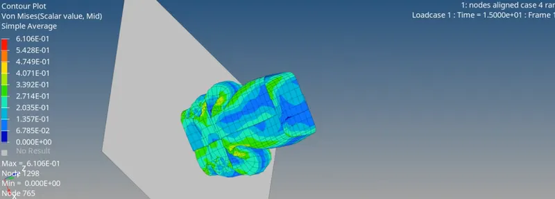
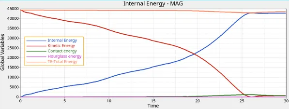
- Internal energy keeps increasing at some point due to the buckling of the tube, the more energy absorbed by the tube when deformation takes place that's why the internal energy increases after some point.
- Kinetic energy decreases from maximum due to internal energy increases.
- Compared to previous cases contact energy slightly decreases after some point due to the absence of notches.
- Total energy also slightly decreased after some point due to contact energy. Hourglass energy is constant due to the presence of recommended properties.
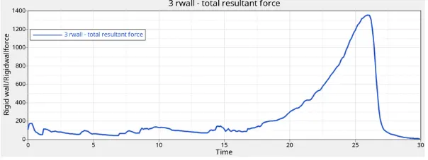
- In this case, the RWALL force graph peaks after some point due to a large amount of force is transferred to the rigid wall during the collision of the crush tube. After the deformation was completed, the graph decreased suddenly and got a constant value after the deformation. The total resultant force peaks at 1350N.
CASE-5:- Create a new notch in the middle ,select the whole section and run.
- In this case, we used case 4 file there are no notches or boundary conditions, but this case equired craete a notch through the middle section of the crush tue. Form this, i have used translate tool for creating new notch.
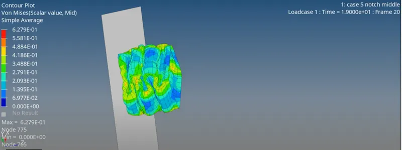
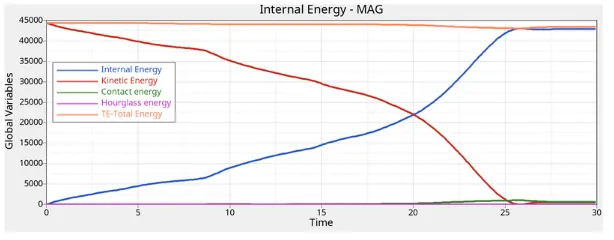
- Internal energy keeps increasing due to the deformation that takes place. Kinetic energy decreases due to increases in internal energy. While contact energy slightly changed in early and also noticeable. It because the depth of the notch increased from previous cases. The total energy also increases earlier due to increasing in contact energy. Hourglass energy due to the presence of recommended properties.
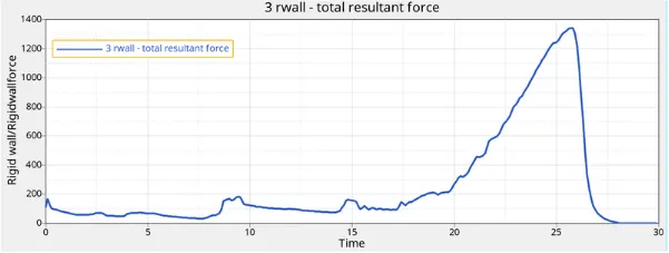
- RWALL force peaks at some value due to the absorption of some energy created during collision and when the tube is completely crushed, the value decreased and got constant.
CASE-6:- Create a new notch with nodes only from opposing 2 faces and run.
- In this case, notches created at the same place on the opposite direction through translate command.
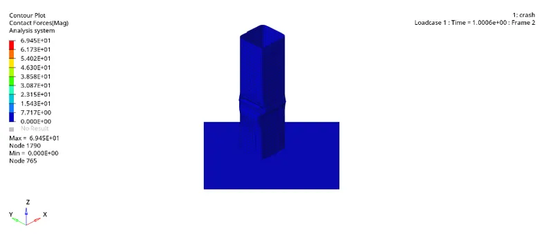
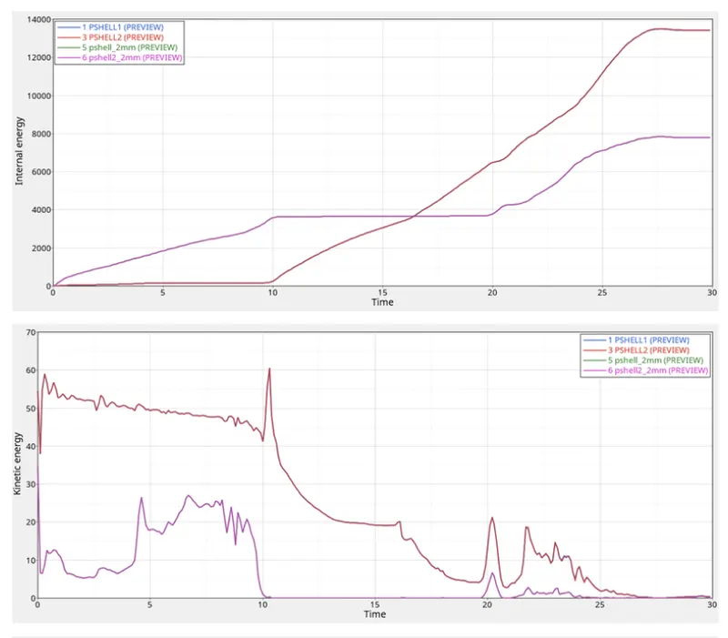
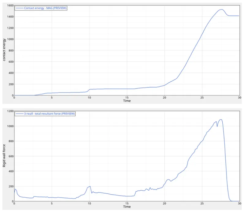
- For the simulation, the max contact force is created as 69.45N where as the time history for all the components are created in order to study the deformation and energy variation in each components with respect to time.
- The internal energy for the 2mm shell components is increasing at the begning because it is attached to the rigid wall and deform smoothly there is notch on the middle opposite surface where as the stiffness is less. The interal energy for the 3mm shell componenets is zero for 10ms and linearly increasing to deform at a velocity 13.3m/s. The end of this components defined the rigidity with a translational (Z- direction) DOF. The total energy for all the four components is varying individually with absence of boundary conditions.
- The kinetic energy for the 2mm shell components is varying at the begning fo the 10ms and maintained as constant which means no more deformation occures because of notch area presents over the components deforms very quickly. The kinetic energy for the 3mm shell components is continuously varying over the time 25ms means deformation takes place at a velocity of 13.3 m/s.
- The contact energy is varying at a very small amount at the begning and there is a sudden peak formed because there is large amount of energy developed at the end of deformation. The overall elements are becoming overlapped or compressed which will develop large force on the rigid wall around 1100N and energy created 1.5KJ.
- When objects collide, contact force transfer energy so as to change the objects motions. When two objects interact each one exerts a force on the other and these forces can transfer energy between them. Fields contain energy that depends on the arrangement of thr objects in the field.
CONCLUSION:-
- The bumper assembly model have benn meshed and element size 6mm.
- All the six cases of crash tube have been simulated and results are compared using various energies plots.