Assignment 5
Aim:
Case 1
Create the mesh for bumper assembly,mesh size should be 6mm.
Case 2
Run the crash tube model as it is.
Change the Inacti=6 and run.
Create the type 11 contact and run.
Remove both notches and remove boundary condition on rigid body node then run.
Create a new notch in the middle ,select the whole section and run.
Create a new notch with nodes only from opposing 2 faces and run.
Process:
Case 1:
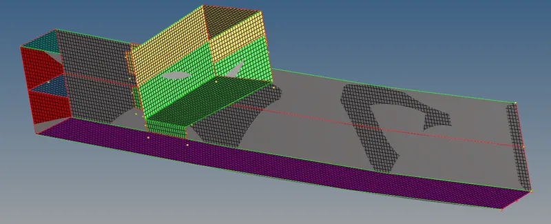
With the mesh size as 6mm we have meshed the bumper assembly.
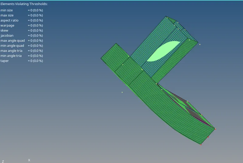
Quality index for the mesh:
For joining the parts
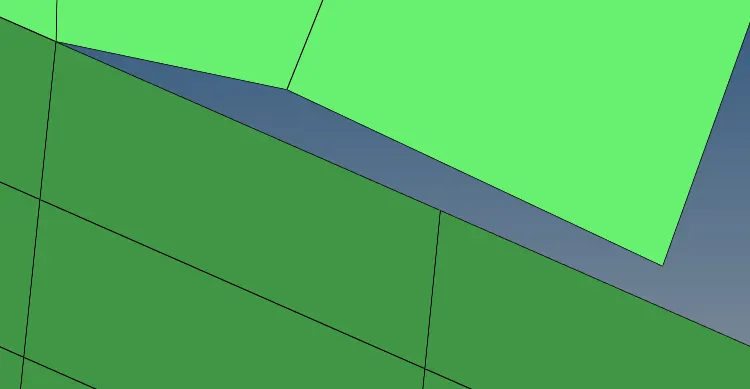
In this component there are some parts which will be separated for joining the single component with the other component
Press F3-> there appears replace and with
Now click the node and other node on the surface in which we have to join with.
Once that is done the surface has to be smoothed so that the component gets matched to the other component for the futher process.
For that 2D -> smooth-> select the element and click smooth
Spot weld
Now after meshing the component some parts of the component are are connected to the main component for that we are using the spot weld.
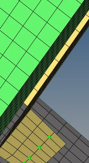
The spot weld which provides a rigid body between the master node and the slave node.
For that connectors-> spot weld -> spot-> select the node -> give the tolerance -> select the component in which between the weld has to be created -> now click create.
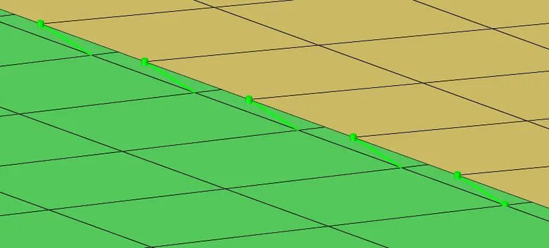
The component which is spot weld in the component and made into a single component.
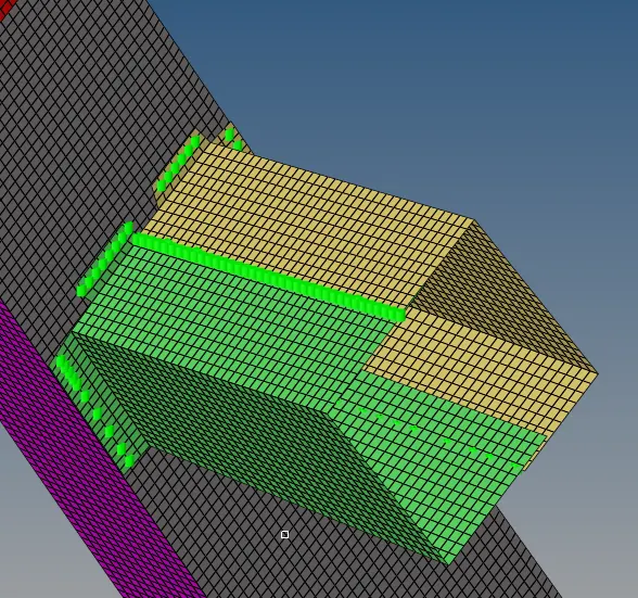
Case 2:
Running the crash tube without any changes.
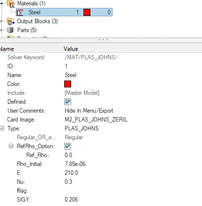
Here the default card image used is M2 PLAS_JOHNS_ZERIL as shown above.
SEAM WELD which is type 2 interface
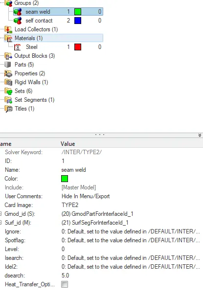
SELF CONTACT which is type 7 interface
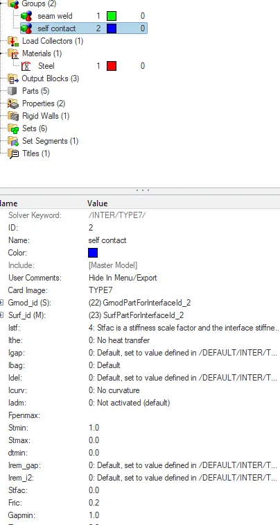
Creating a TH part in the output block
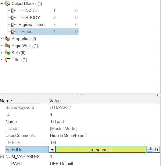
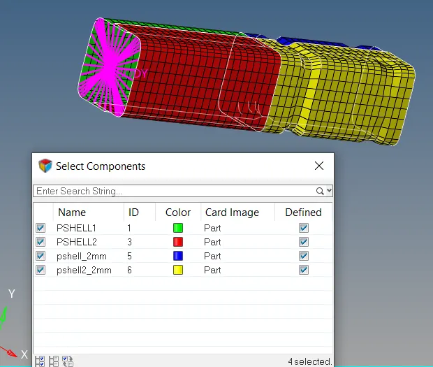
After importing the starter file there appears a component.
Now it is stimulated and there gets a block which stimulates the component.
Now we have got h3d file which is imported.
The stimulation of the Von Mises.
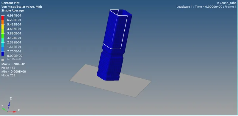
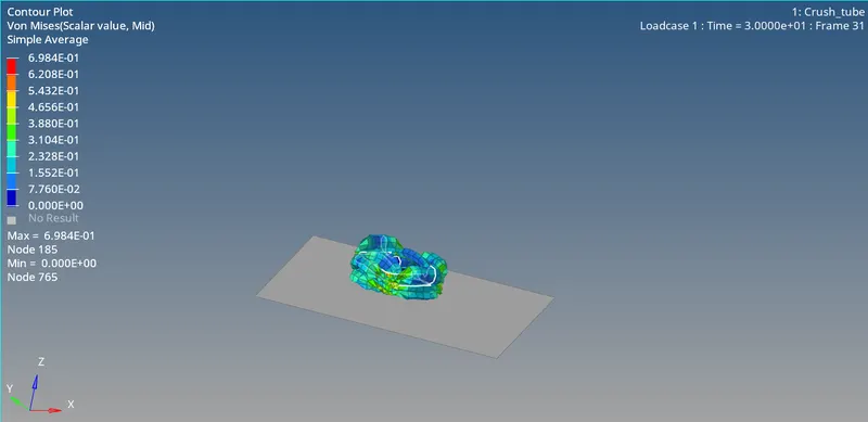
The file T01 is used for plotting the graph.
Internal energy graph:
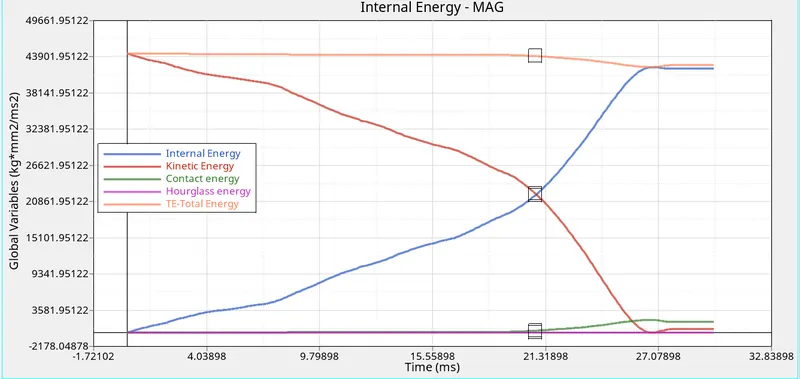
The internal energy at starting will be at raising slowly due to the deformation of the crush tube. After the whole deformation of the crush tube occurs the internal energy goes in the constant positions because there will be no deformation occurs.
The complete deformation occurs at 30s.
Rigid Wall graph:
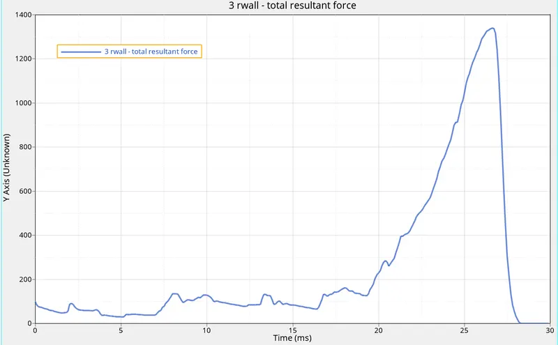
The rigid wall increases smoothly during the impacting, The rigid wall withstand the impacts according to the impact given the node.
During impacting the highest impact shows the time of 26s after the impact it gets reduced and drops to zero.
Case 2(1):
Change the Inacti=6 and run.
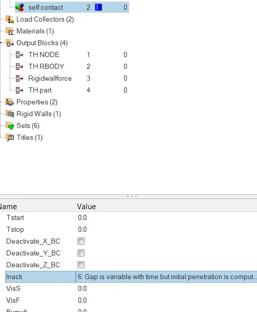
After apply the parameter that the inacti=6, the stimulation is runned.
The stimulation of the Von Mises
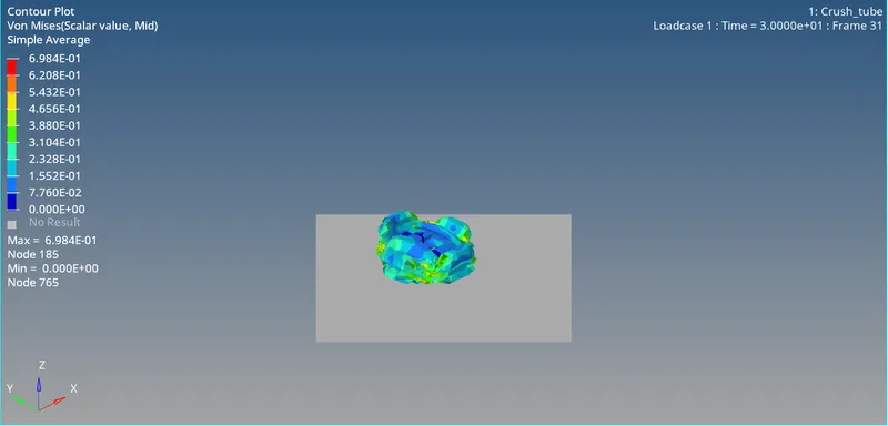
The To1 file is mported for plotting the graph after the input of the parameter
The plotted graph of internal energy:
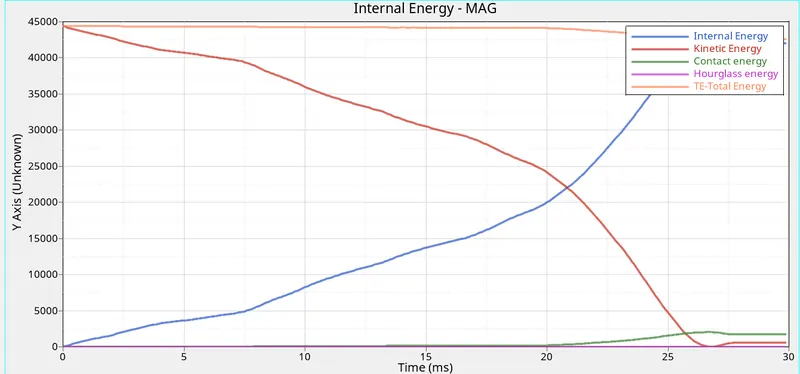
The internal energy which goes on increasing due to the deformation of the crush tube once the rupture occurs completely in internal enrgy curve occurs in stable condition. The internal enrgy occurs at a 28s
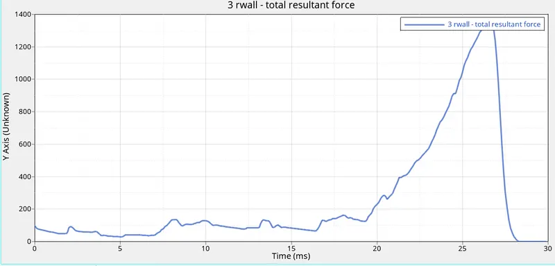
Here the rigid wall crash occurs slightly high compared to the previous part. The crush occurs at a time of 28th sec. The force will be increasing due to the rigid body will experience more in the contact force. After the particular time there will be no contact between the master and slave node so the energy drops to zero.
Case 2(2):
Create the type 11 contact and run.
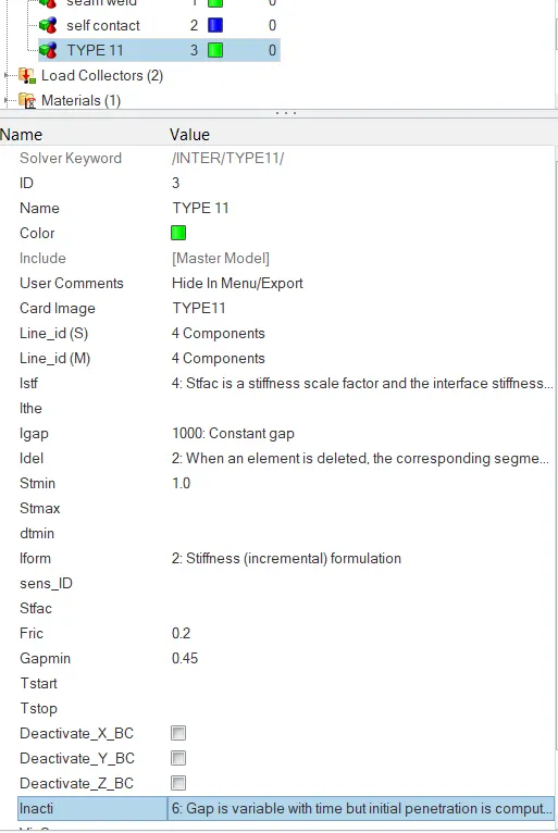
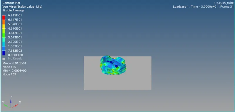
After creating the type 11 element the stimulation is done.With the h3d file the Von Mises is stimulated.
With the T01 file the graph is plotted.
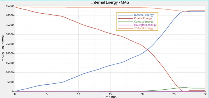
The internal energy which goes on increasing due to the deformation of the crush tube once the rupture occurs completely in internal enrgy curve occurs in stable condition. The internal enrgy occurs at a 28s. The internal energy decreases due to less absorption of the energy.
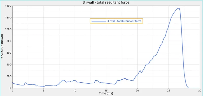
Here the rigid wall crash occurs slightly high compared to the previous part. The crush occurs at a time of 28th sec. The force will be increasing due to the rigid body will experience more in the contact force. After the particular time there will be no contact between the master and slave node so the energy drops to zero.
Case 2(3):
Remove both notches and remove boundary condition on rigid body node then run.

Here clicking ton the rigid body untick the selected boundary condition.
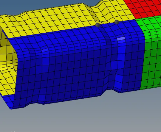
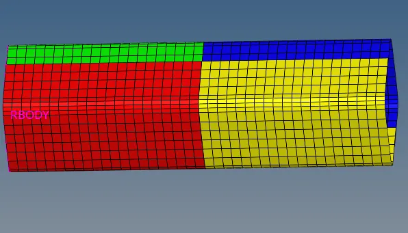
For removing the notch from the surface go to geom-> node edit -> align node-> select the notch to be remove and then click align the node will be removed as per the above image
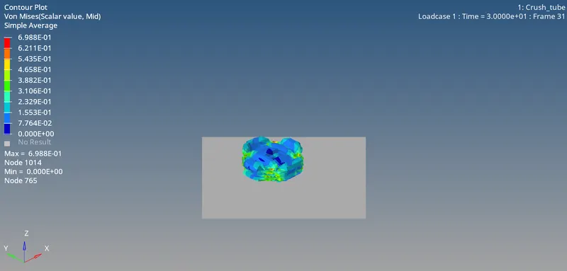
After removing the boundary conditions and the removing the notch the stimulation is runned and occurs a block with the help of the file h3d file the contour plot is plotted. The above image shows the Von Mises diagram
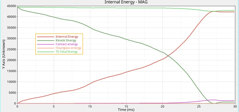
With the help of the T01 file the graph is plotted for the internal energy and for the rigid wall. The internal energy which goes on increasing due to the deformation of the crush tube once the rupture occurs completely in internal enrgy curve occurs in stable condition. The internal enrgy occurs at a 27s. The internal energy decreases due to less absorption of the energy.
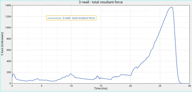
Here the rigid wall crash occurs slightly high compared to the previous part. The crush occurs at a time of 27.5th sec. The force will be increasing due to the rigid body will experience more in the contact force. After the particular time there will be no contact between the master and slave node so the energy drops to zero.
Case 2(4):
Create a new notch in the middle ,select the whole section and run.
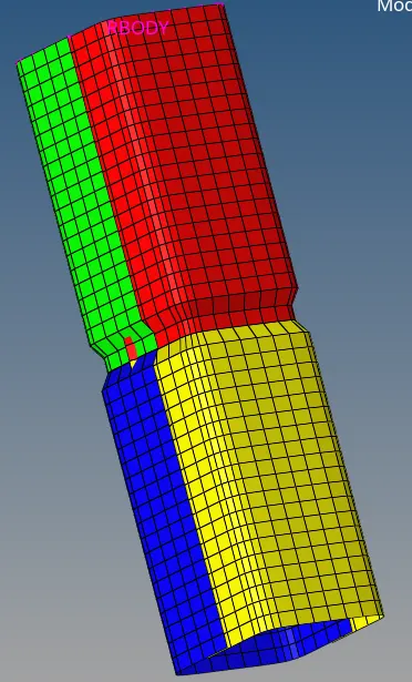
Here the notch is created at the middle of the surface by 2D-> element offset-> 2d elems to offset(elems)-> select the area which need to be offset->keep the distance as 4->and click offset+.
After creating the notch the stimulation is runned and with the h3d file the contour plot is plotted. Below it shows the Von Mises contour plot.
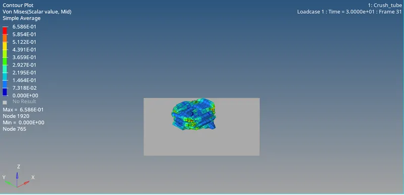
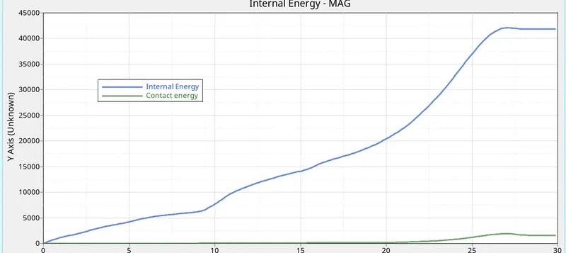
With the help of the T01 file the graph is plotted for the internal energy and for the rigid wall. The internal energy which goes on increasing due to the deformation of the crush tube once the rupture occurs completely in internal enrgy curve occurs in stable condition. The internal enrgy occurs at a 27s. The internal energy decreases due to less absorption of the energy.
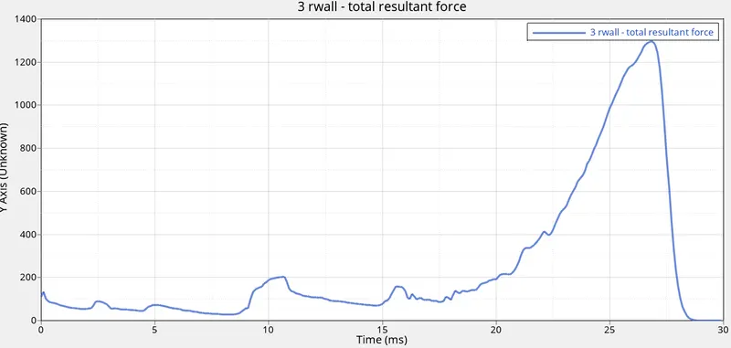
Here the rigid wall crash occurs slightly high compared to the previous part. The crush occurs at a time of 27.5th sec. The force will be increasing due to the rigid body will experience more in the contact force. After the particular time there will be no contact between the master and slave node so the energy drops to zero.
Case 2(5):
Create a new notch with nodes only from opposing 2 faces and run.
With the help of the previous case all the notch on the other side where aligned and created a notch opposite of the face.
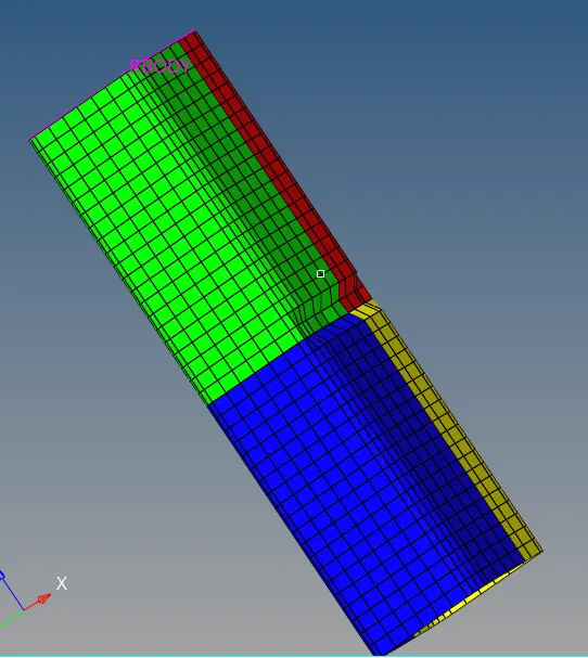
With creating the notch the stimulation is runned and the block appears. With the help of that the graph is plotted.
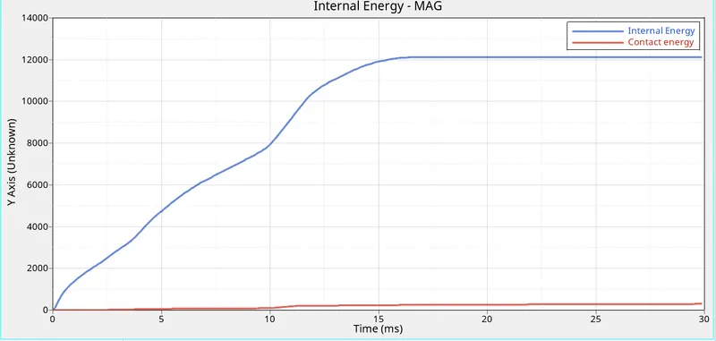
With the help of the T01 file the graph is plotted for the internal energy and for the rigid wall. The internal energy which goes on increasing due to the deformation of the crush tube once the rupture occurs completely in internal enrgy curve occurs in stable condition. The internal enrgy occurs at a 27s. The internal energy decreases due to less absorption of the energy.
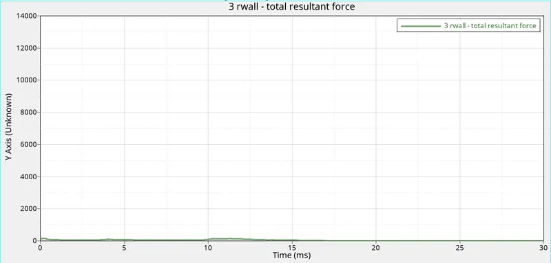
Here the rigid wall crash occurs slightly high compared to the previous part. The crush occurs at a time of 27.5th sec. The force will be increasing due to the rigid body will experience more in the contact force. After the particular time there will be no contact between the master and slave node so the energy drops to zero.
Conclusion:
The conclusion from the result is that the contour plot and the graph changes according to the changes of the parameter.
For case 2:
No. of cycle=83600
Energy error=-3.8%
Mass error=0
Elapsed time=210.35s
For case 2(1):
No. of cycle=83600
Energy error=-3.8%
Mass error=0
Elapsed time=319.86ss
For case 2(2):
No. of cycle=83600
Energy error=-4.0%
Mass error=0
Elapsed time=356.08ss
For case 2(3):
No. of cycle=73100
Energy error=-3.0%
Mass error=0
Elapsed time=285.00s
For case 2(4):
No. of cycle=82800
Energy error=-3.7%
Mass error=0
Elapsed time=225.81s
For case 2(5):
No. of cycle=79000
Energy error=-0.7%
Mass error=0
Elapsed time=182.58s
Result:
In case 4 removing the notch reduces the rigid wall contact force. In case 2(5) notch on the opposite faces maximises the contact force.