Assignment 5
AIM:To get a meshed structure of a bumper assembly and to get a crash tube model after a different simulation process which is being stated in the 6 different question.
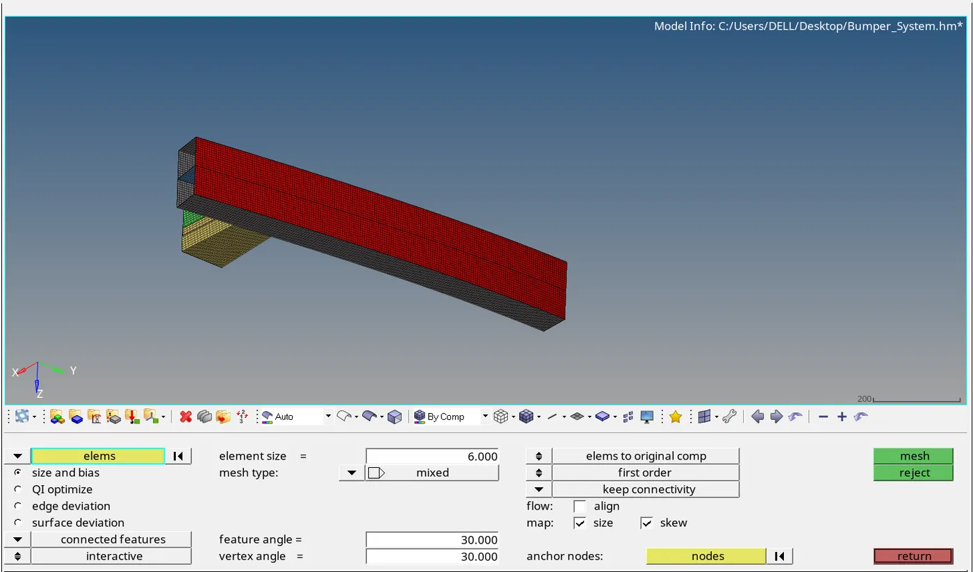
PROCEDURE:The mesh includes the element size of 6mm of bumper assembly and using automesh we can have the mesh on the respective part of assembly.The mesh quality includes quads elements with very less trias are considered to be a considerable quality of mesh.In the image we can see that respectively.
1.Run the crash tube model as it is.
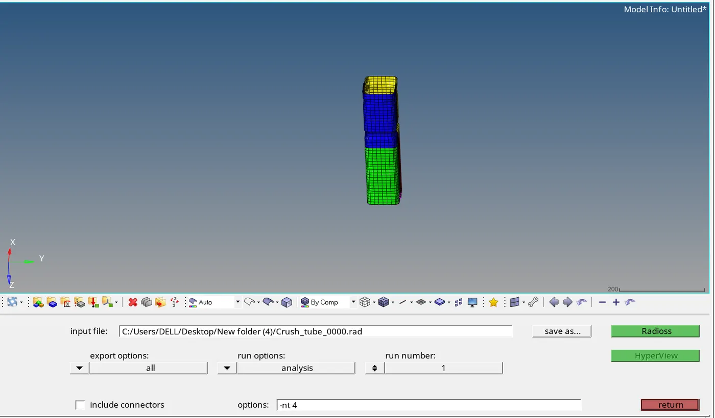
Ans:We have got a model of crash tube which undergoes in simulation for that firstly we got to save it then under analysis we have radios which executes the simulation.The image shown below of crash tube and the simulation icon.
Now after running the simulation we have got the Rad out file of 0001 we tells us about the errors of masses and energies also cycle time also the elapsed time etc are shown below:
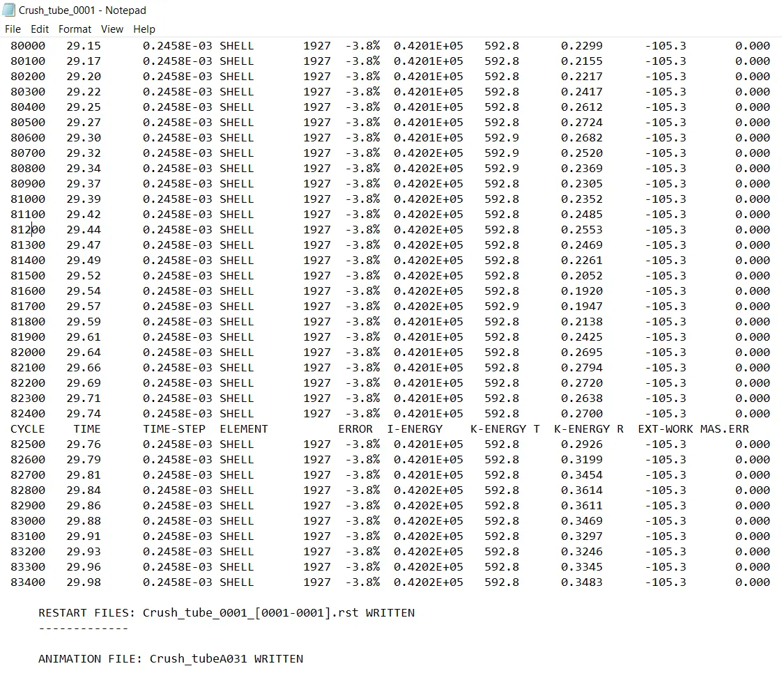
Now from this detail we get are as follows:
ELAPSED TIME:171.01sec
TOTAL NO.OF CYCLES:83469
ENERGY ERROR:-3.8%
MASS ERROR:0%
These errors are allowable and permissible because energy is in the range of -15%-5% of error and the coming errors are exist in between.
Now shifting the mode to hyperview to get a animation of the given component along with the ranges upto it vary for which we gotta load a h3d file for that and then we resume.Also change the mode to contour mode so that we can have the desired animation for that.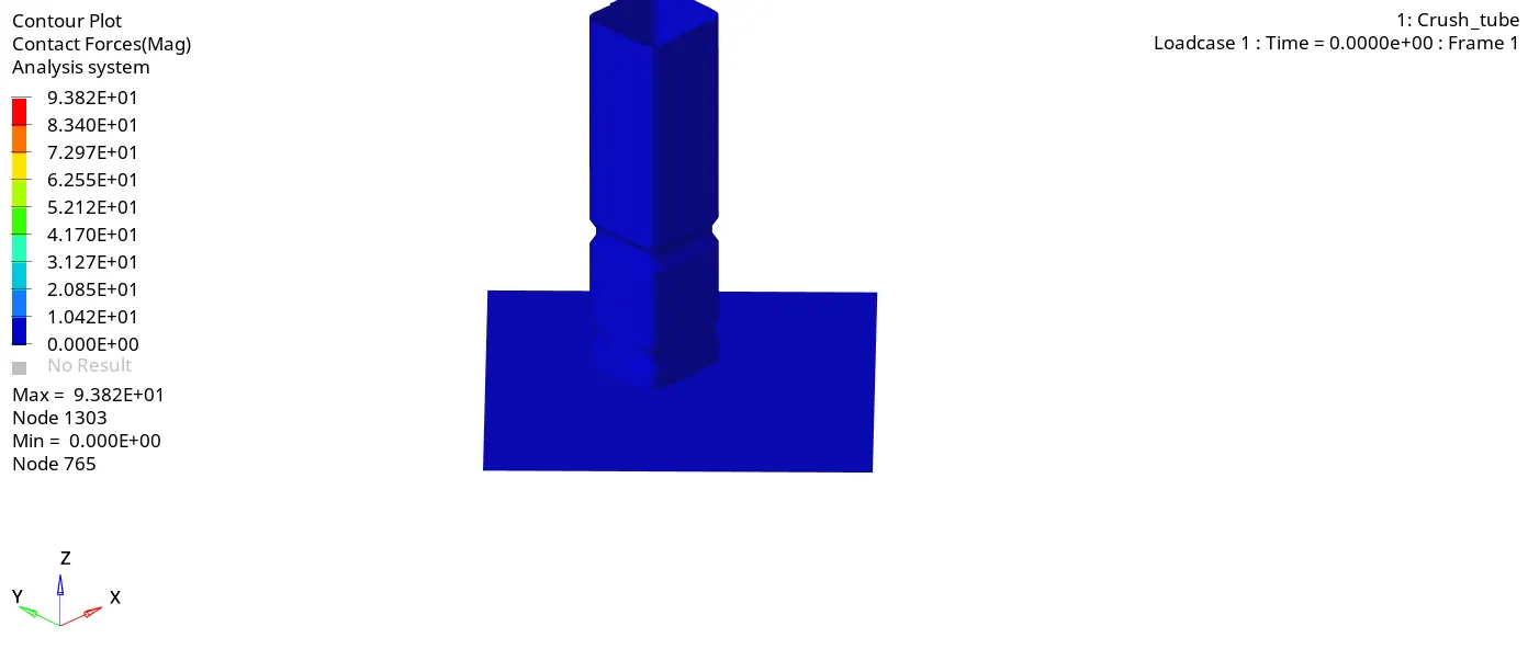
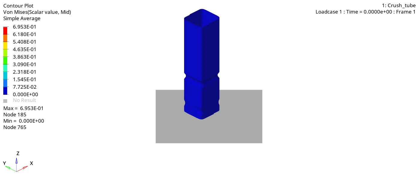
After having a certain animation we proceed with certain no. of graphical views for that we should proceed to hypergraph 2D and then we need to load the T01 file after it we got to go to various graphical representation shown below respectively:
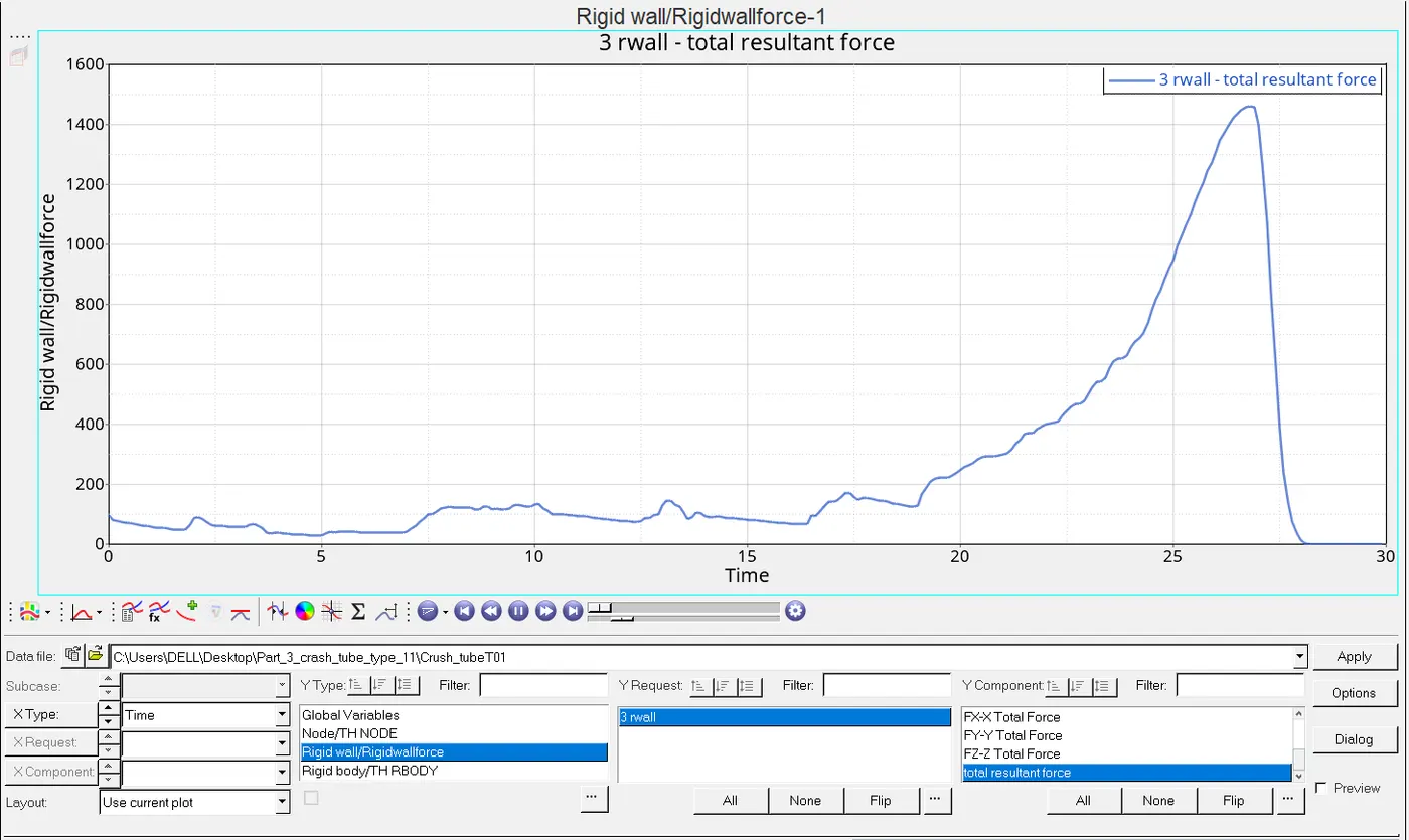
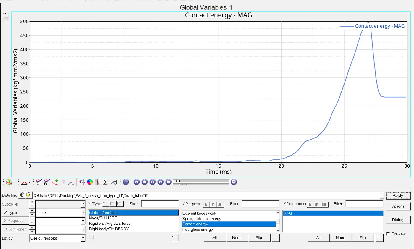
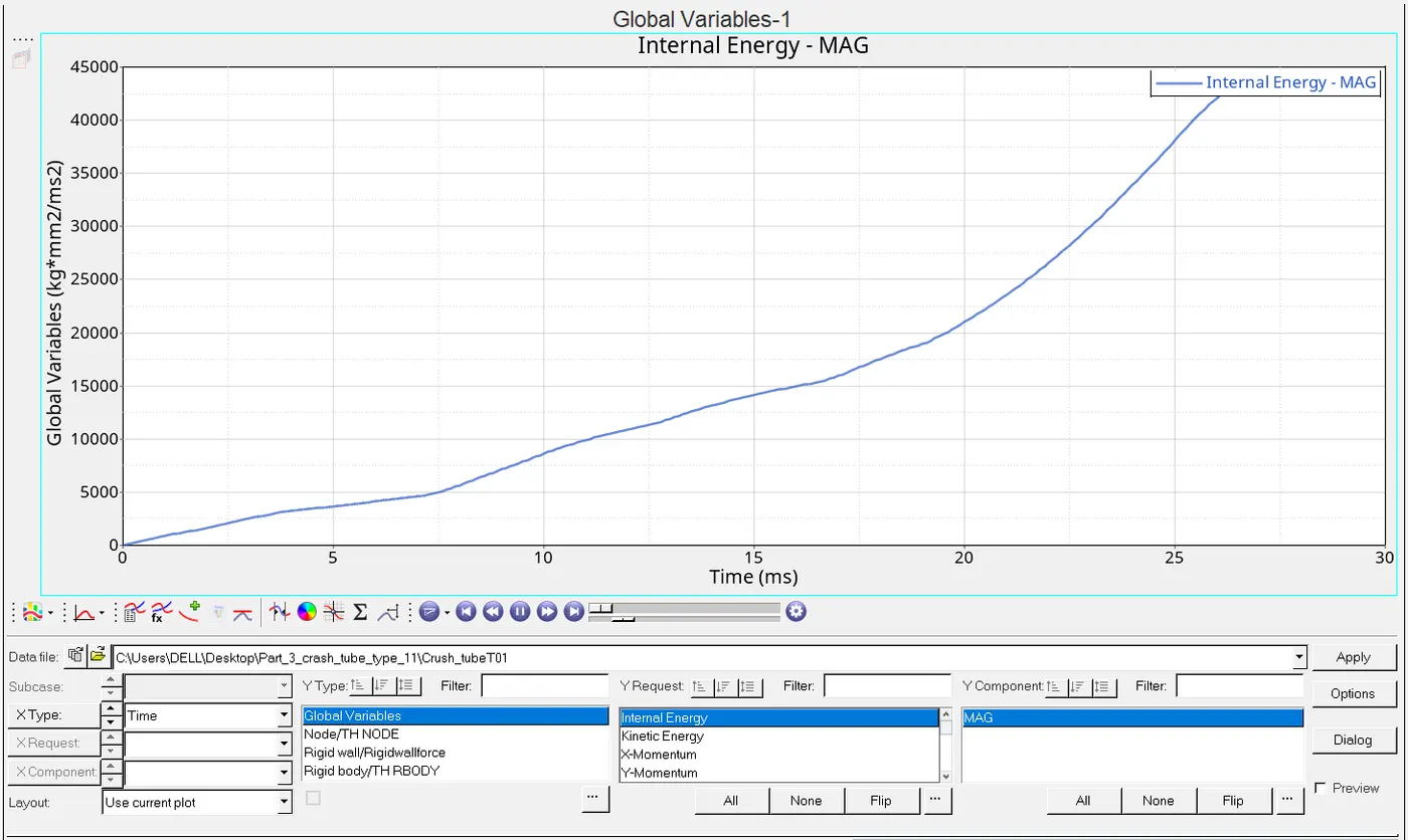
The plots which is being question are RWALL Forces,CONTACT FORCES,INTERNAL ENERGY
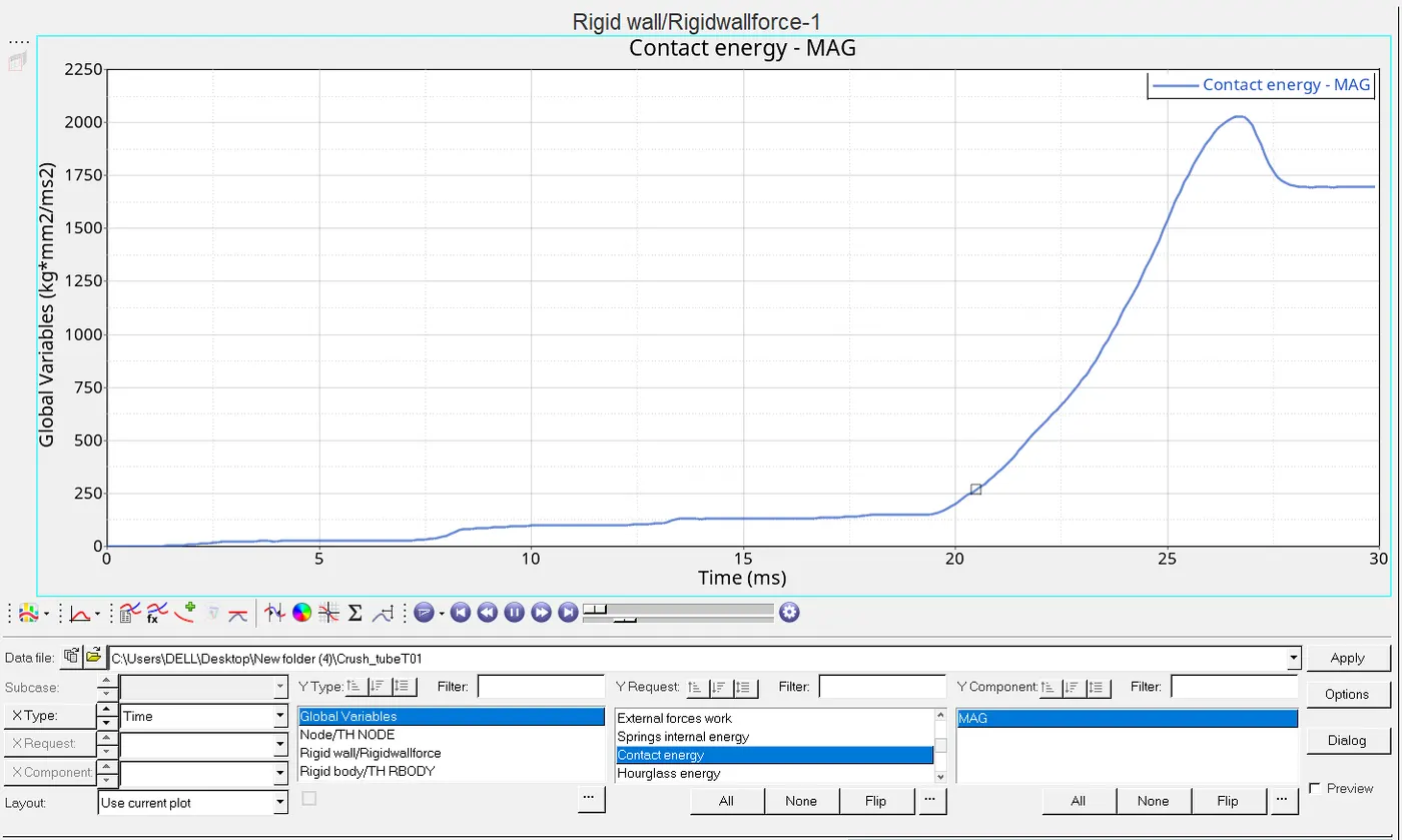
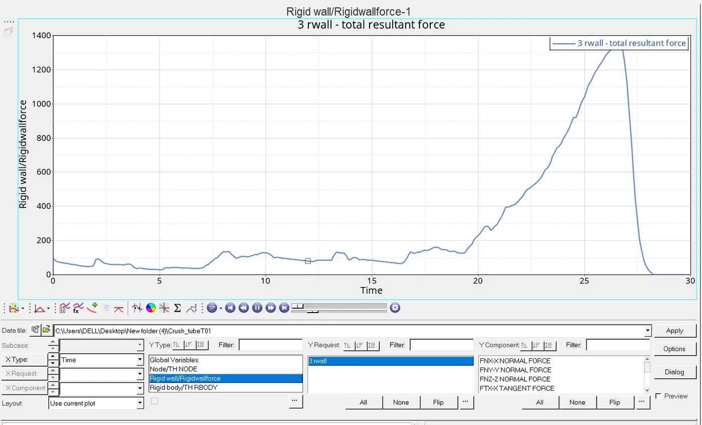
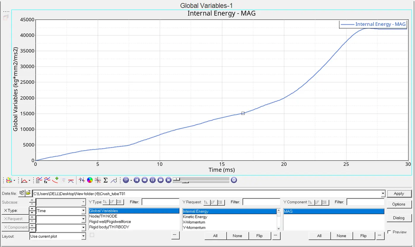
2.Change the Inacti=6 and run.
ANS:In order to that we gotta go to the group icon and select the self contact and there we get a Inacti icon which is more precisely shown in figure:
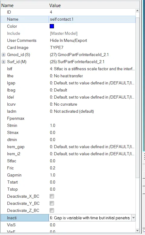
Then we execute the simulation separately in radios after termination of the simulation we get a new rad file of 0001 out which tells the error in the various energies and mass but before that we take look to the radios image then we go to the rad file image and details.

Now the image of rad file after the changes has done according to question is being asked.
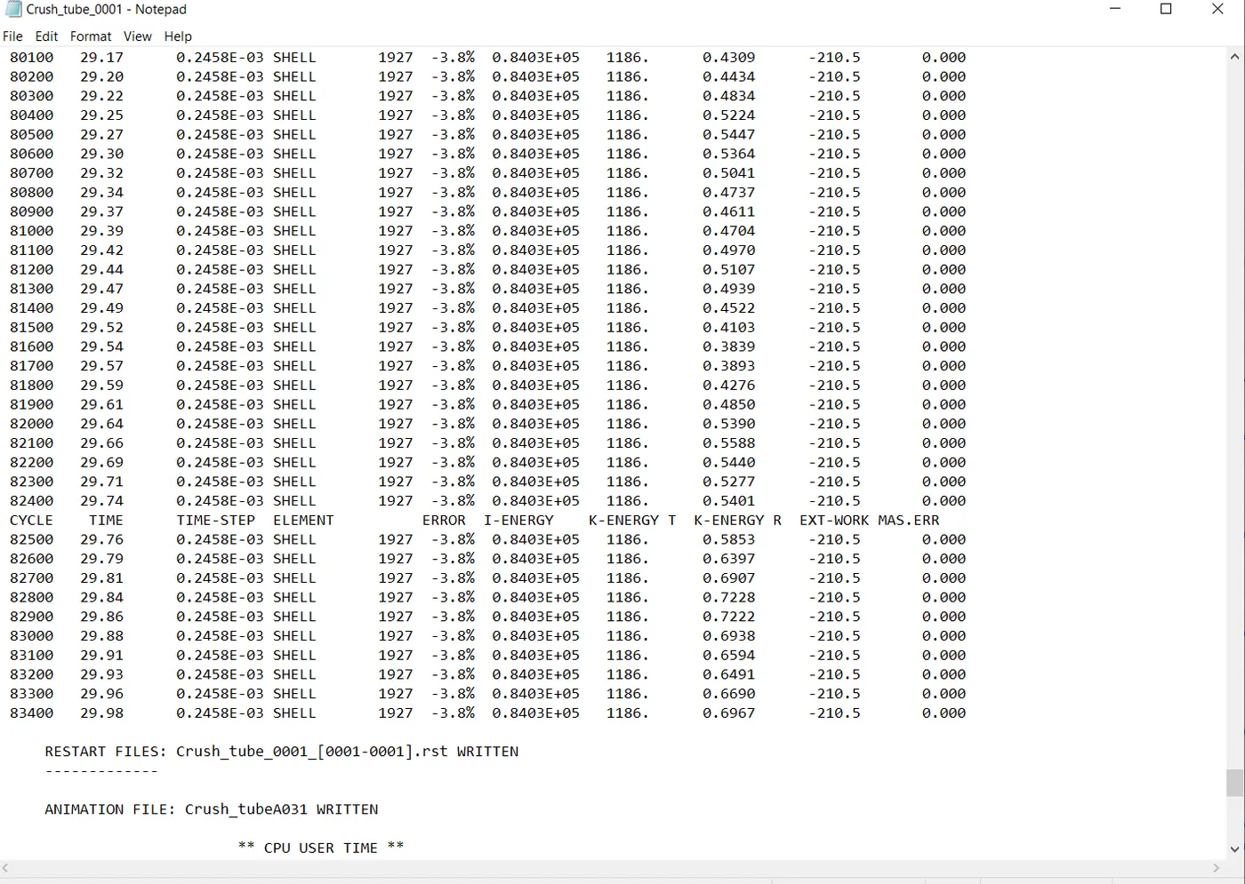
ELAPSED TIME=453.49sec
TOTAL NO.OF CYCLES=83469
MASS ERROR=0%
ENERGY ERROR=-3.8%
since this change also taken as consideration due to energy error criterion is getting fitted with the consideration norms.
Shifting the mode towards the hyperview mode and then we load the h3d file then we gotta see the animation file which is being asked in question.Also the mode gets shifted in the contour mode then whatt we have as shown below:
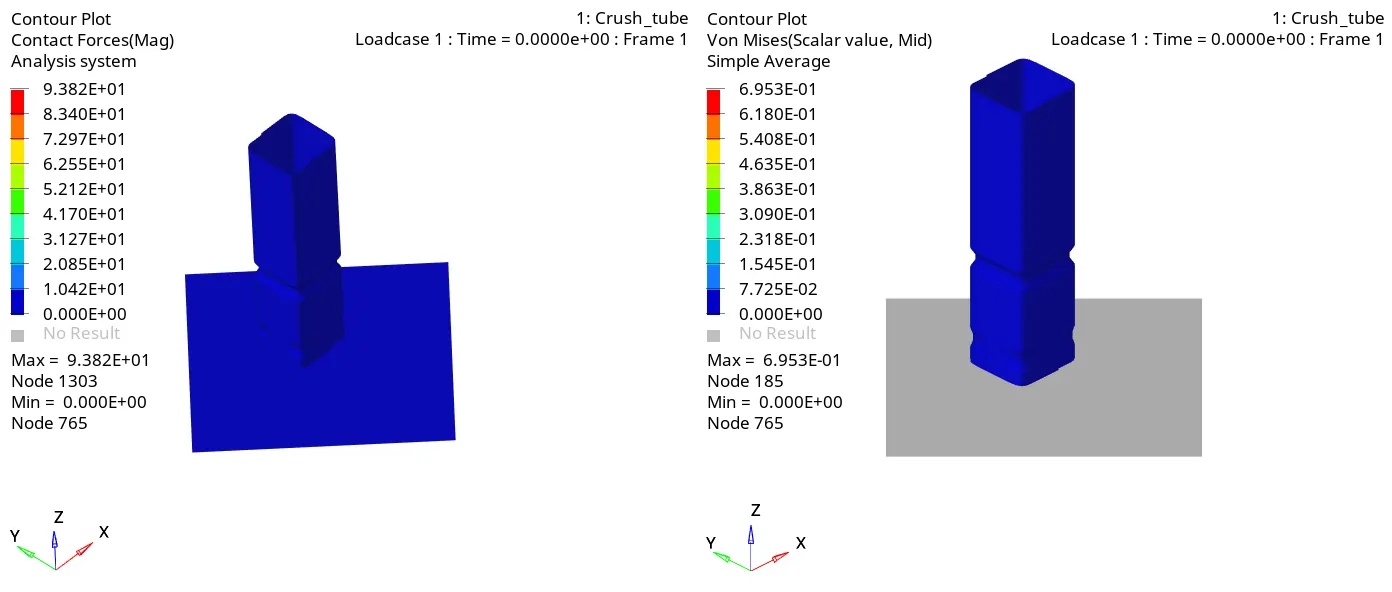
Here the maximum contact force is 93.82N and the max.von misses stress is 695MPA.
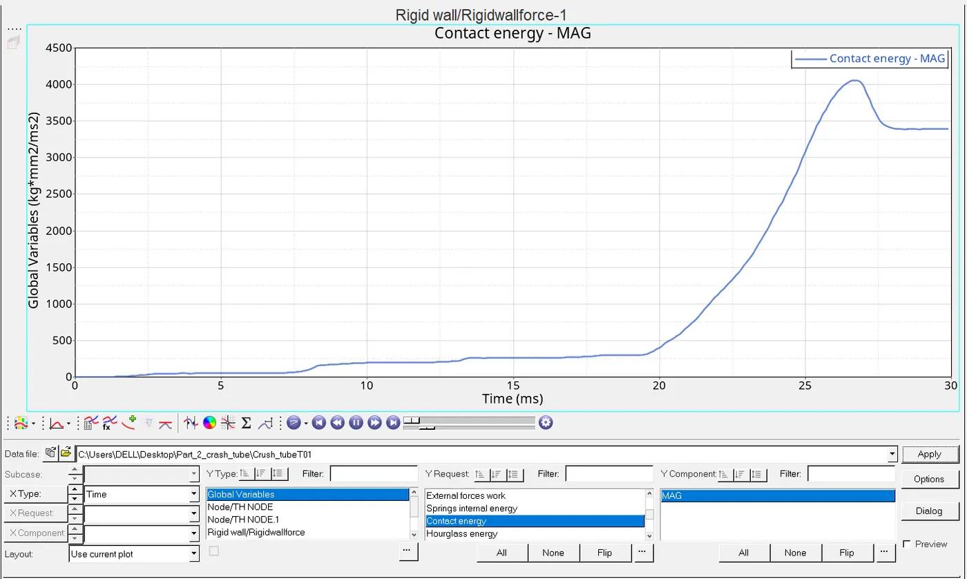
Now the graphical view will be getting from the hypergraph 2D for that it is required to shift the mode also load the file of T01 file.The plots are shown which is being asked as follows:
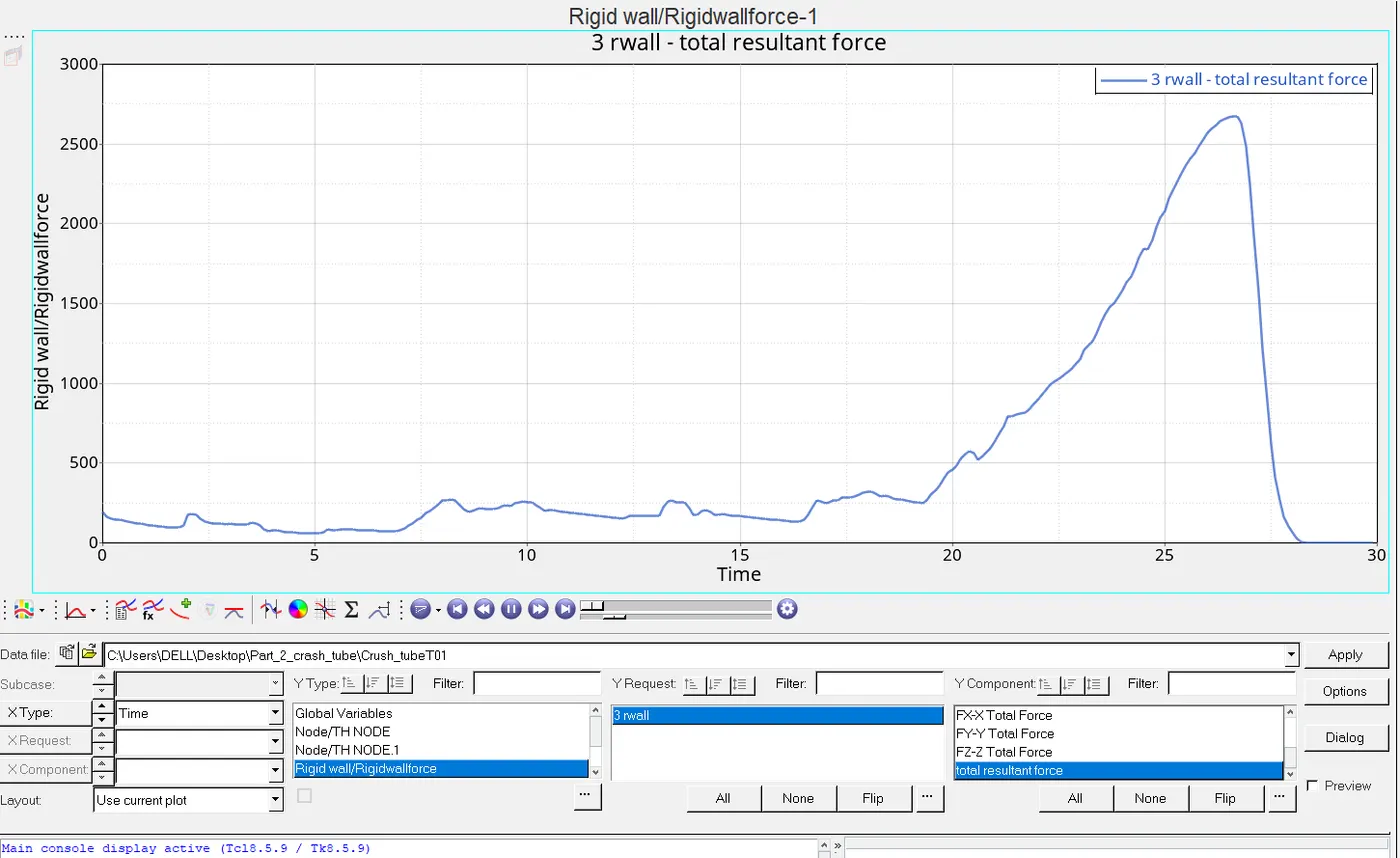
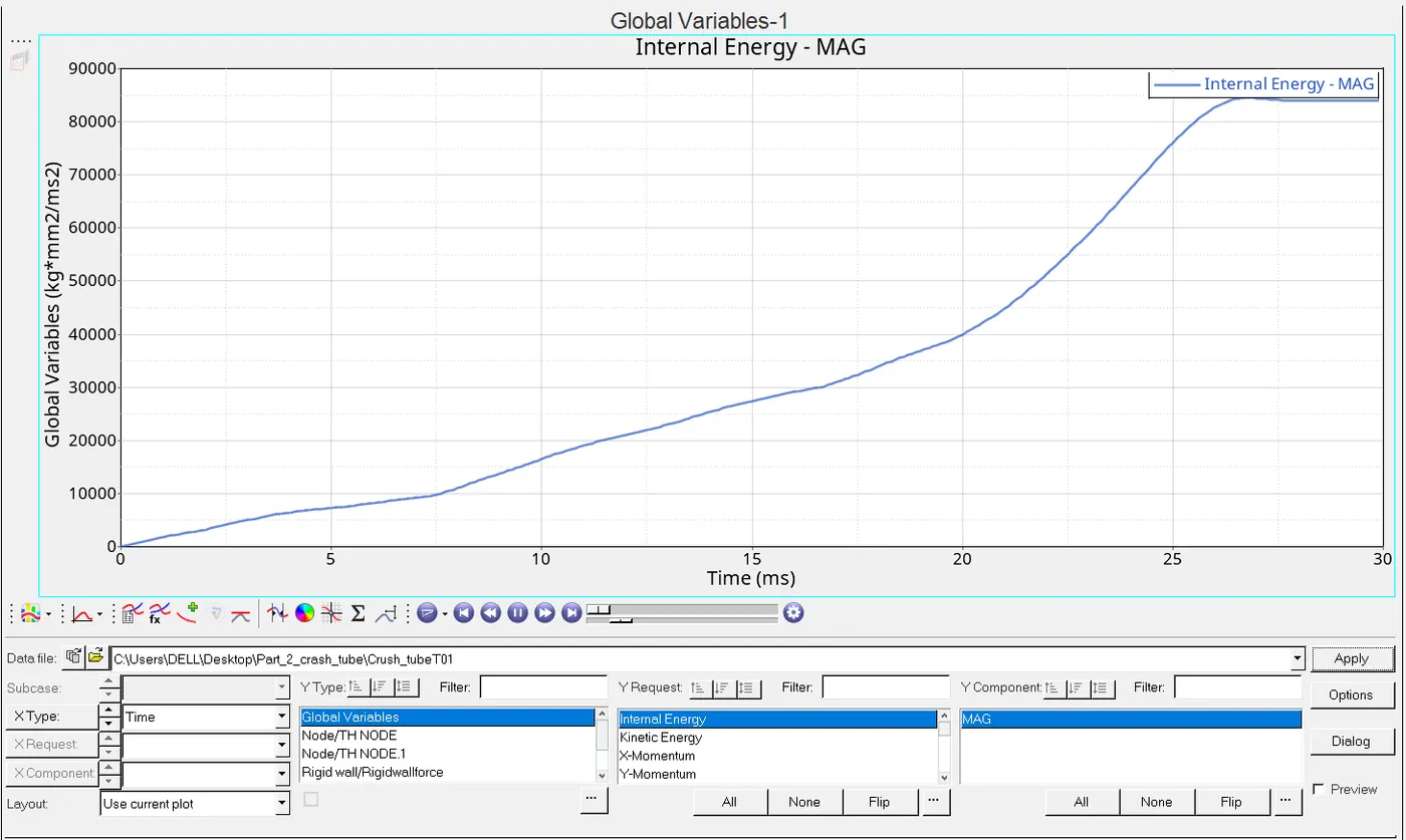
3.Create the type 11 contact and run.
ANS:For this we have to create a group under to it we gotta assign card image as TYPE11
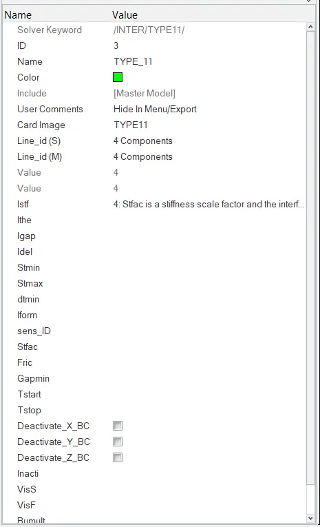
After execution of Radios we proceed towards the Rad out file of 0001 to look the details of the errors shown below:
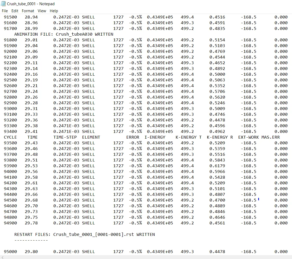
Here the observation are got listed below:
1.TOTAL NO. OF CYCLES=95796
2.ELAPSED TIME=246.74sec
3.ENERGY ERROR=-0.5%
4.MASS ERROR=0%
Now shifting the mode to hyperview to get a animation,for that we have to load a h3d file and shifting the mode to contour mode to get the animation shown below:
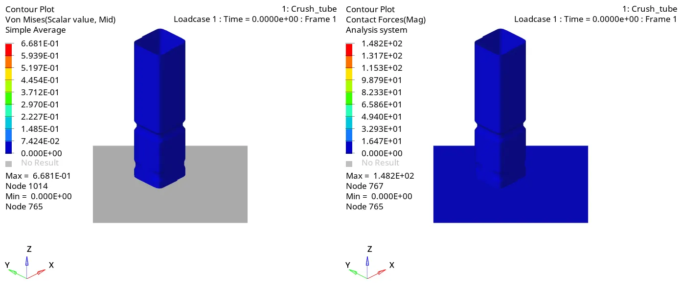
The max von mises stress is 668MPA and max contact force is 148.2KN
After this changing the mode to hypergraph 2D to get a graphical representation for which it is being asked and it is required to have a T01 file load to get a view:
4.Remove both notches and remove boundary condition on rigid body node then run.
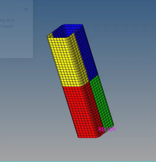
ANS:In order to do a geometry notch we can use align or translate either will work whereas in this i have used a align to make geomtry shown below.
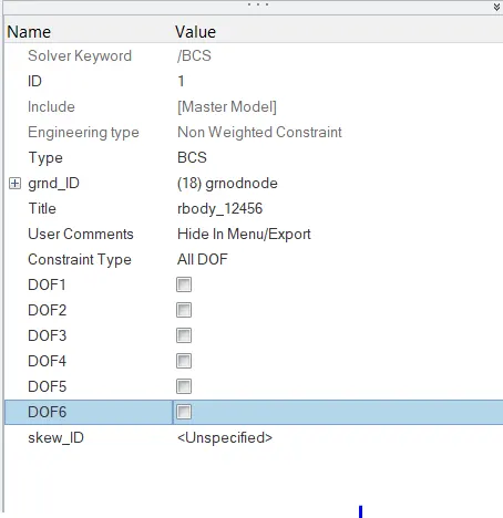
Now moving to the boundary condition we should move to solver and in BCS all DOF is needed to put off shown below:
Now the rad file of it shown below:
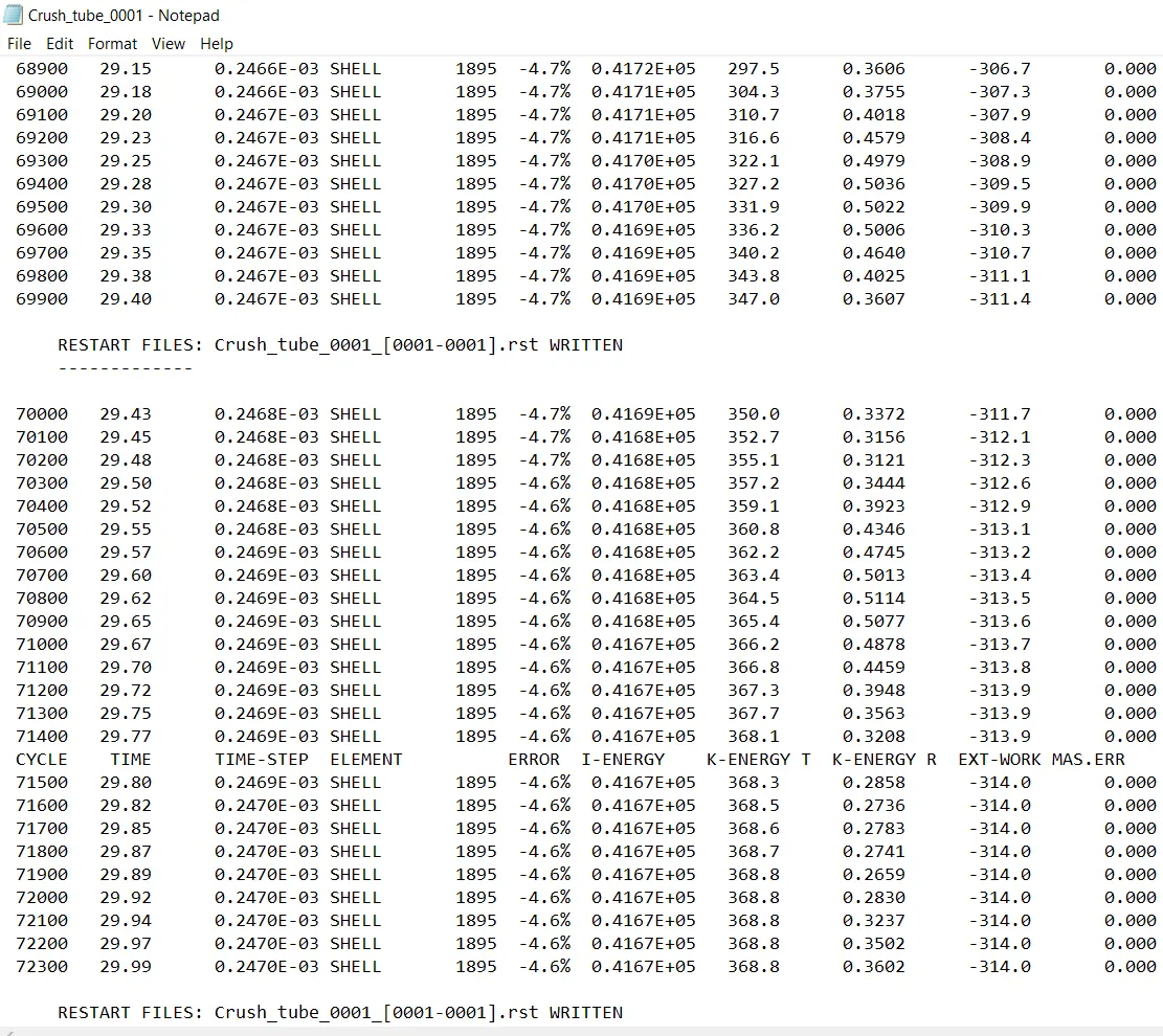
TOTAL NO. OF CYCLES:72328
ELAPSED TIME:147.41sec
ENERGY ERROR:-4.6%
MASS ERROR:0%
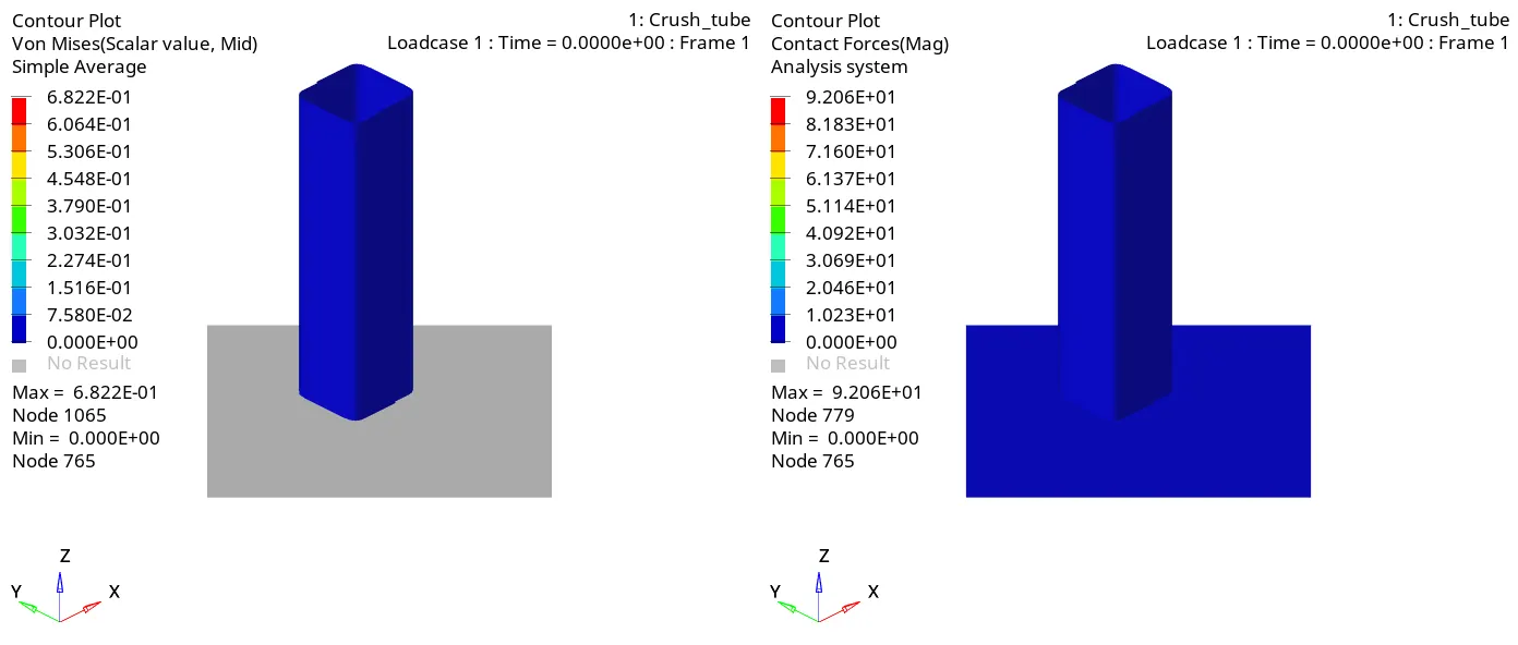
shifting the mode to hyperview and loading to h3d and in the contour mode:
Now loading T01 file and shifting mode hypergraph 2D:
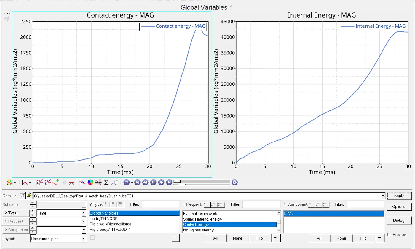
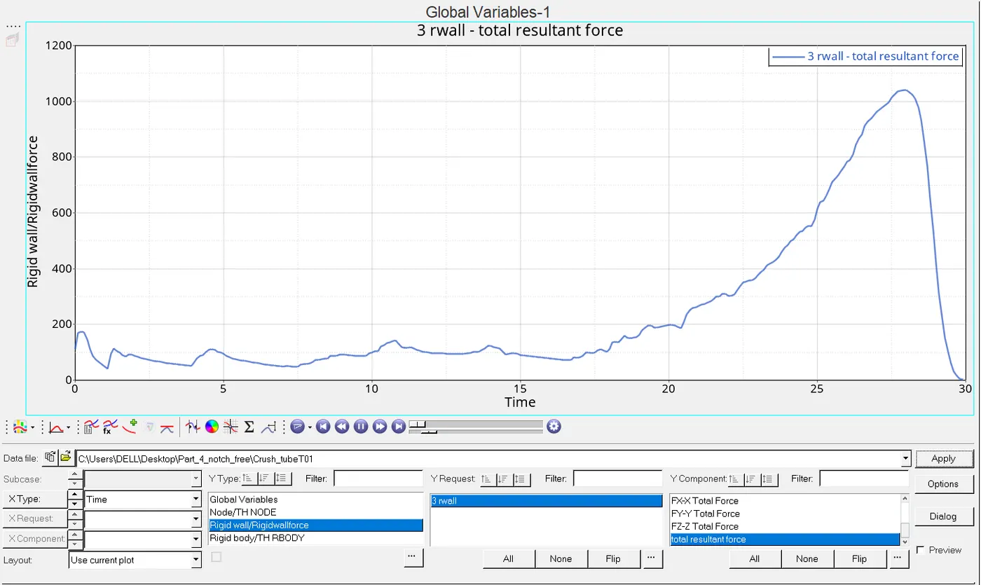
5.Create a new notch in the middle ,select the whole section and run.
ANS:middle notch can be done using translate option under which translate+ and translate- both will work in order to shift the nodes,faces and points.
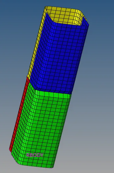
Creating a notch in between which is being asked in the question.
Now moving to the similar process which is being done above.First take a look to the rad file shown below:
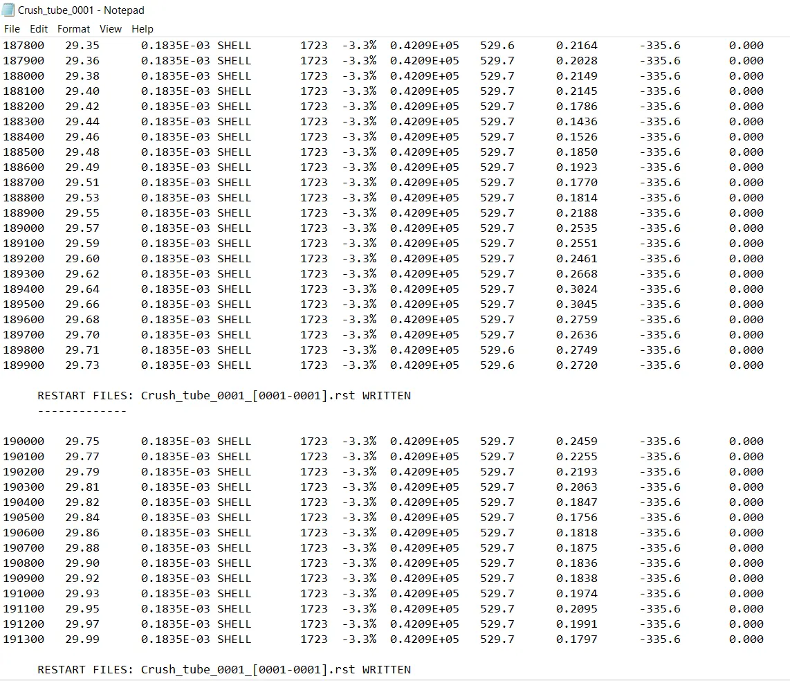
TOTAL NO. OF CYCLES=191362
ELAPSED TIME=367.5sec
ENERGY ERROR=-3.3%
MASS ERROR=0%
Now the h3d file gives the animation in hyperview we can have it in the contour mode.
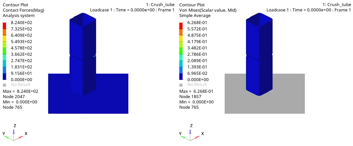
Now loading T01 file in hypergraph 2D:
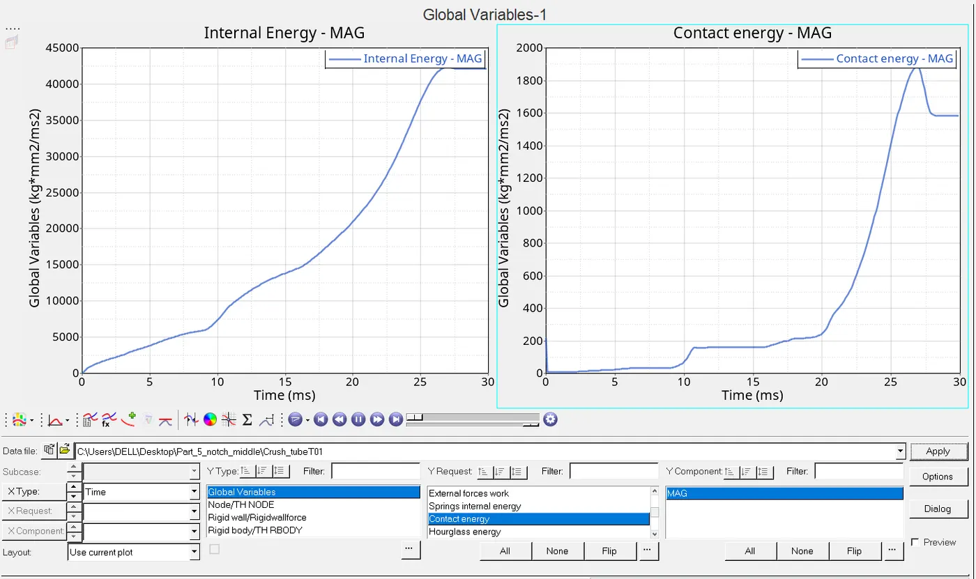
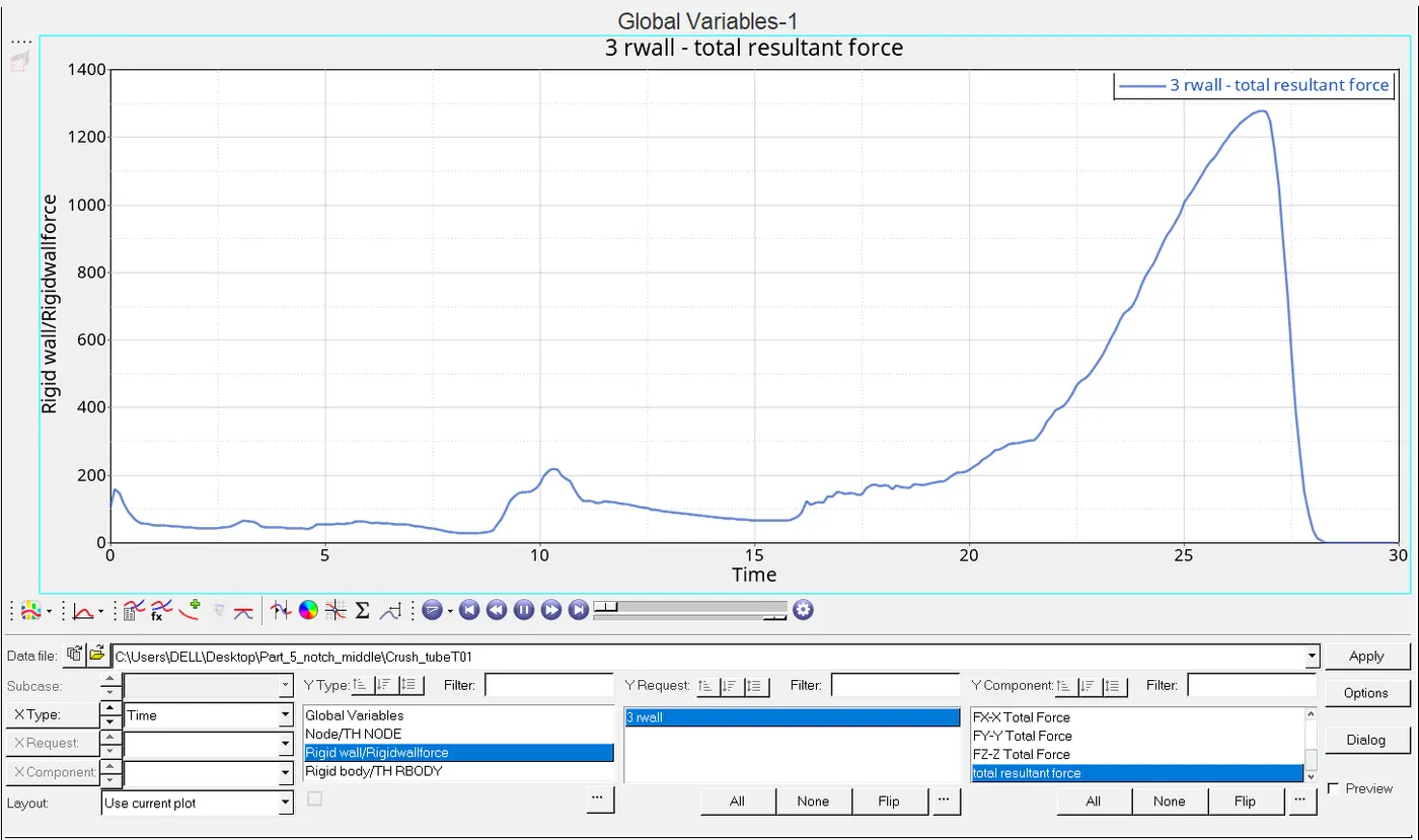
6.Create a new notch with nodes only from opposing 2 faces and run
ANS:In order to that we again the same option that we have which is translate.
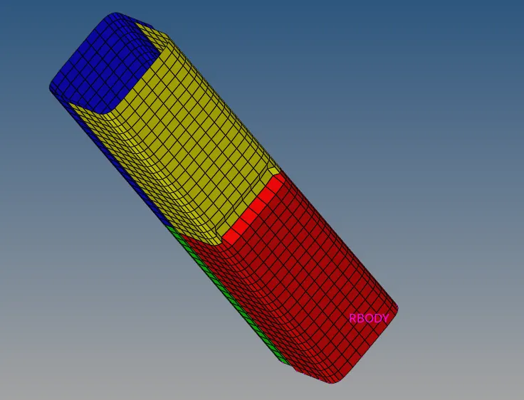
something like shown above in the image.
Now the rad file of it of 0001 out file shown below gives the various information.
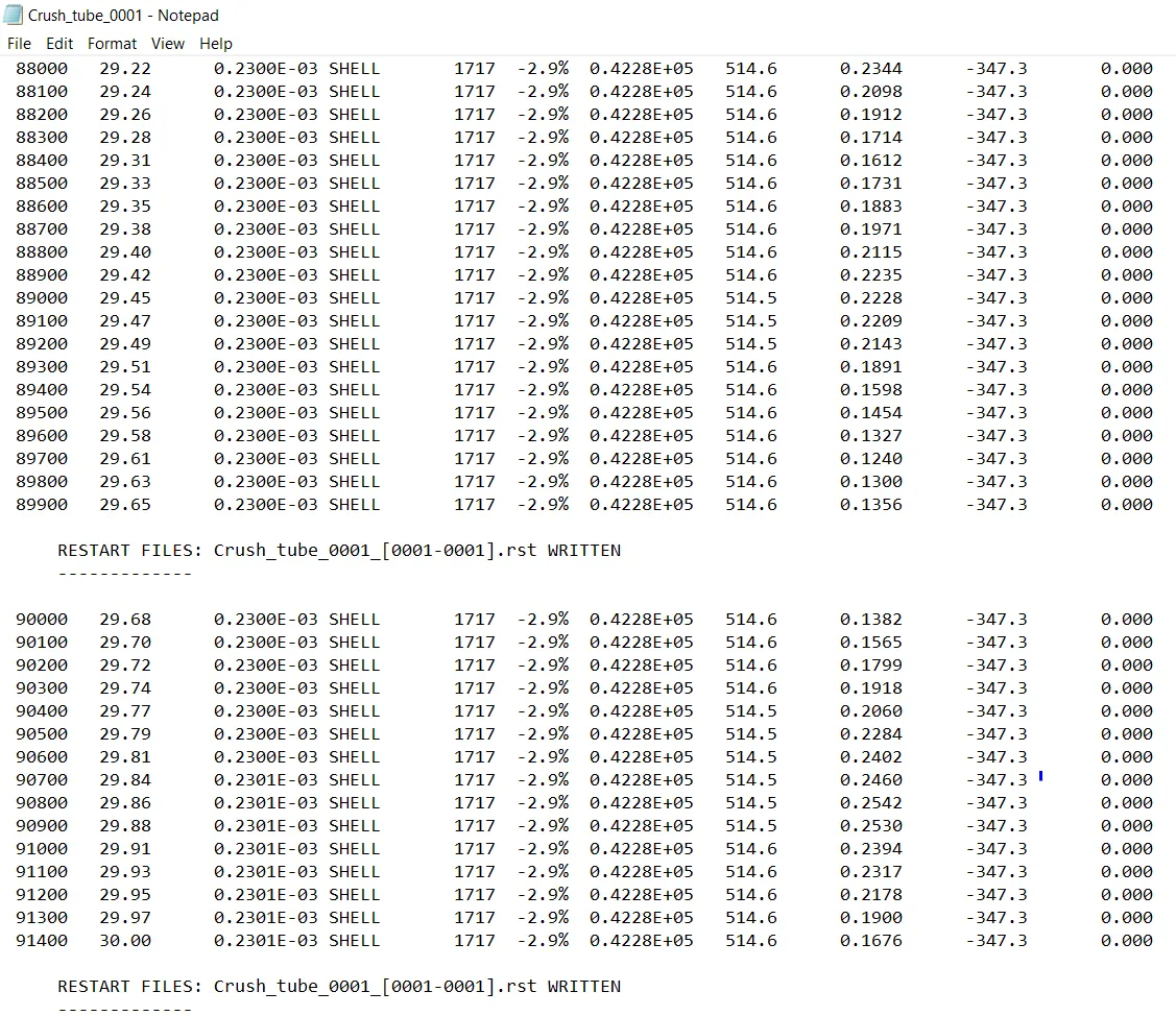
ELAPSED TIME=183.81sec
TOTAL NO.OF CYCLES=91412
ENERGY ERROR=-2.9%
MASS ERROR=0%
Now again to the h3d file which shows animation in contour mode shown below respectively:
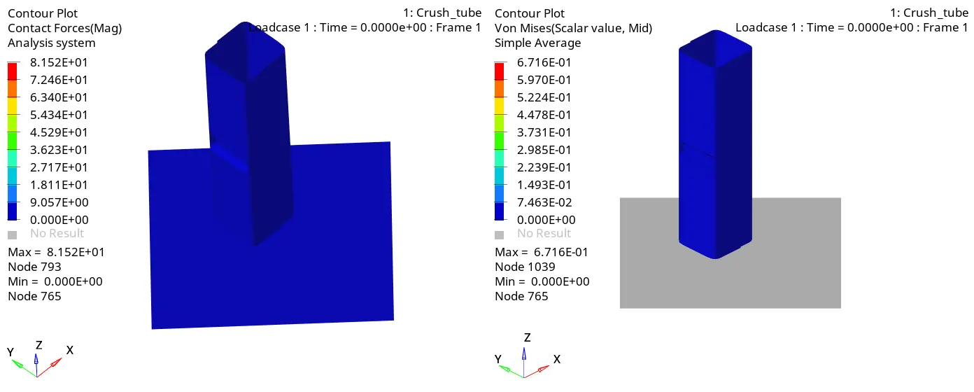
Here the observation tells the max.contour force and von-misses stress are 81.52KN and 671.6MPA
moving ahead in hypergraph 2D to get a graphical representation of the following stated above.
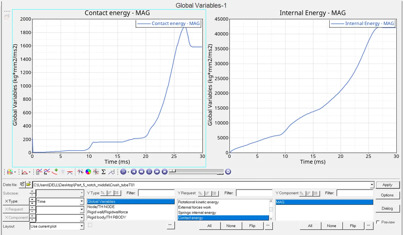
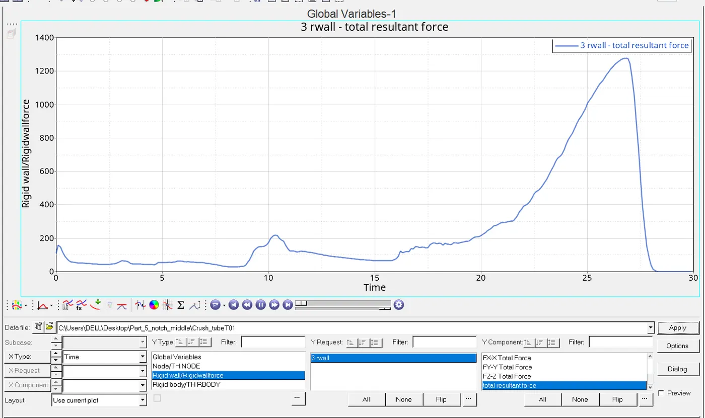
DESCRIPTION:In the inacti=6 reduced the gap between masters and the slave along with whatever cases we have seen can be considered beacause it does not fails the designated criterion of energy i.e -15%-5% .So the removal of notches leads to decreament in the no. of cycles vice versa results the increament in it.Also it is very obvious to have notch free design results in the less errors it could be in mass error or in the energy error,since in all the cases we have mass error is zero but energy error is very low in notch free .Likewise we can have the less simultion time in notch free section as well.
Contact energy seems to very low in the no notches part and highest at the opposite surface notch section it may be due to addition of notches in those area are manual and due to this contact force gets increased because the surface gets more closure or come in contact or may be due to penetration in them
CONCLUSION:
(A)Here we got to know about the notches removal and addition procedure along with its demerits and merits and also understood there simulation methods.
(B)Also gotta understand about the Rwall forces and there representation on graph