Assignment 5-Bumper meshing and simulation under given condition
AIM:
Here our main aim is to create a mesh for the bumper for the given size and to run a simulation for the given conditions.
Solution:
-So initially we will have to import the file model in hypermesh format (.hm format) by clicking on file>import >model.
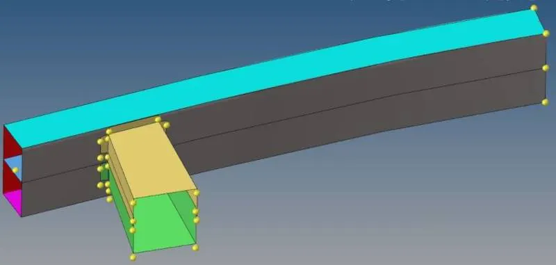
-Now we need to perform a geometry clean up (to remove the free edges) for the model by using surface edit option.To perfrom trim with surface go to main menu page>geom>surface edit>trim with surf/planes.
-Now we need to perfrom the meshing for the model with an element size of 6mm (main menu>2D>automesh>size and bias>surface).

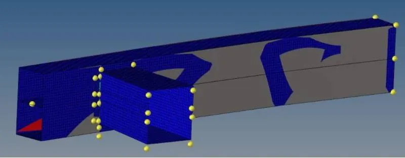
-Now after meshing we now need to do spot welding at the upper and lower crash boxes,to do this go to main menu>2D>connectors >spot.
-Now in the place of tolerance value we need to enter 10mm and diameter as 5mm also select the type as weld and click on create.
-Below is the welded model.
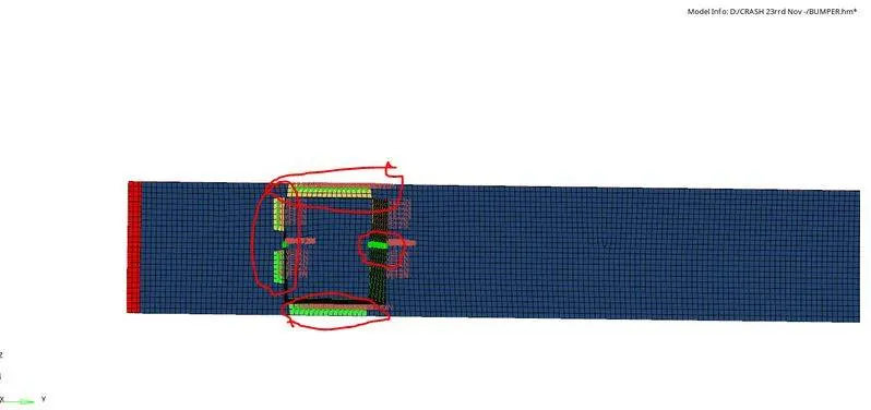
-.Now we have to check for free edges using tools>edges>elements.if we any free edges we can select those edges and then delete them.Now we can save the model.
Crash Impact application:
Type 7- A general surface interface and can simulate all type of impacts between a set of node and a master node.
Type 11-simulation of impact between edge to edge contact application
Type 24-simulation of impact between the surface to surface contact application.
Case 1: To run the simulation as it is
To set up and run the simulation for all the 6 type of condition in hyper mesh,compare and give a conclusion to it.
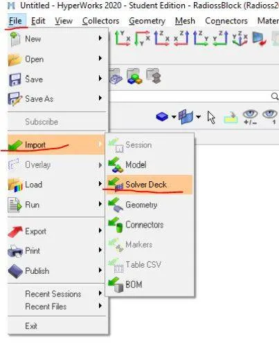
-First we need to import the file in hypermesh by using the option file >import >solver desk ,then select and import the file.
-After importing the model we need to run the model as it is.
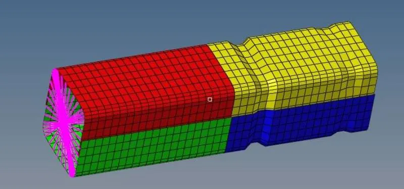
-To run the simulation of the respective model we need to use the option main menu page>analysis>Radioss.Click on save as to change the file dierectory to case 1 folder.
-We now need to select the include selector box and in the space of option type -nt 4 and finally click on radioss to run the simulation.

-After runing the simulation we will get an output as a popup screen stating the job is completed and there by we plot the graph.
-The output will be as follows:
1)Energy and mass error output:
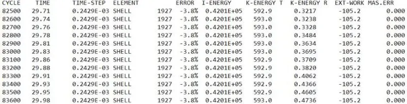
2)animation (.h3d) file
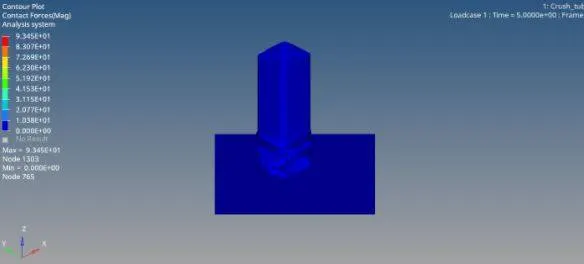
Contact forces
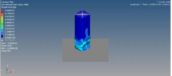
Von mises stress
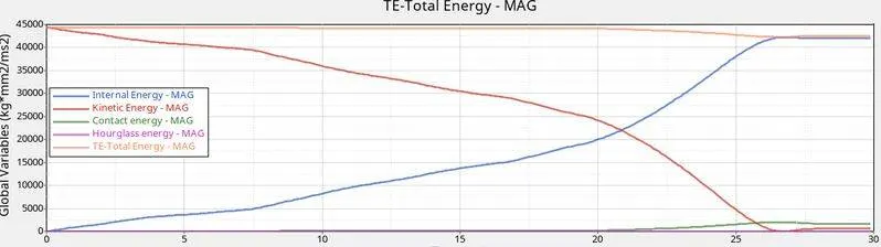
-The total energy plot graph is as folows (Case 1):
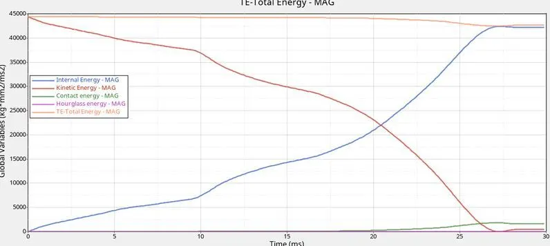
-To perfrom this operation we need to follow the option :Tool bar>change to hypergraph 2D>Now select the data from respective folder>select global variables>internal energy,kinetic energy,total energy,contact energy>MAG>apply.
-The same step is followed for the remaining condition.
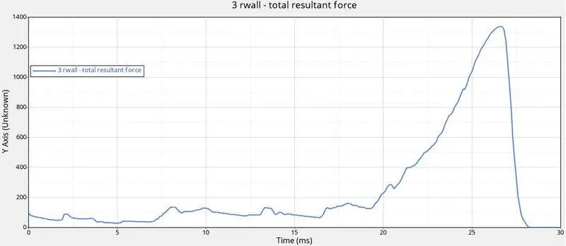
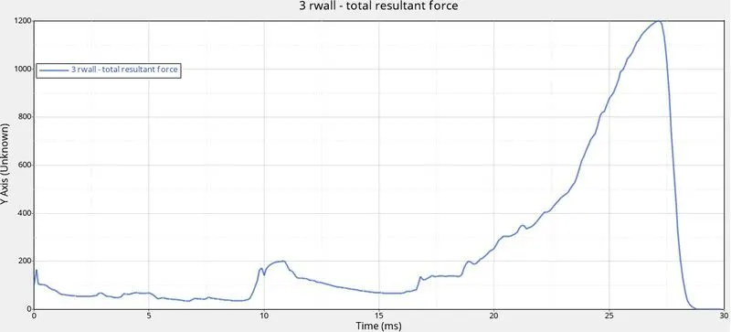
-Now to plot the rigid wall force,click on rigid wall forces>click 3r wall>click total resultant forces>apply.
CASE2:
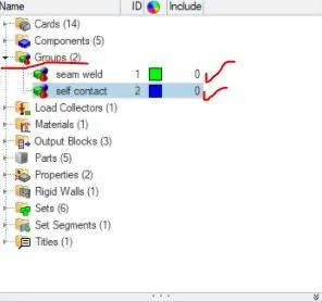
-IN case 2 we need to change the inacti value as 6 and run the simulation in seperate folder.Nowto change the inacti value (the option to deactive stiffness) we need to follow the following option Go to model browser tab>group>self contact option,in the edit inacti value enter the value as 6 which means the gap is variable with time but initial penetration is computed.
-After changing the value we need to run the simulation and save it in a seperate file as case 2.

-After the simulation is runed the output file were obtained and is listed below:
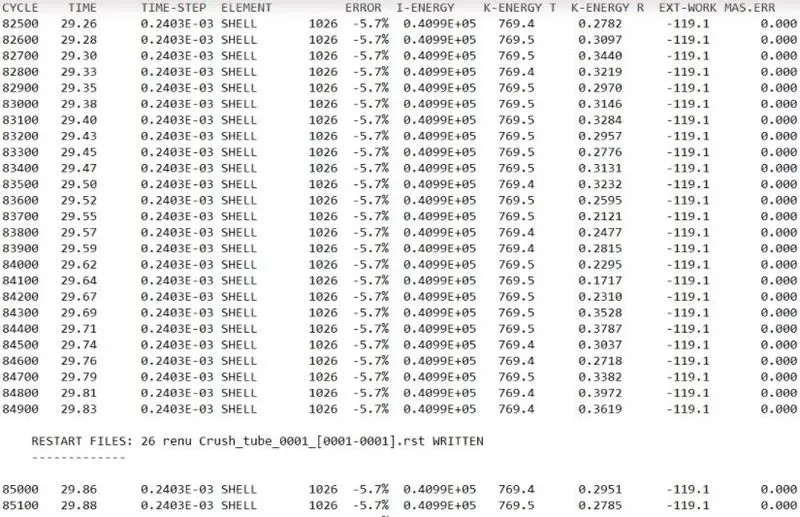
-Mass and energy error are as follows:
-Animation of the case 2 (.h3D file):
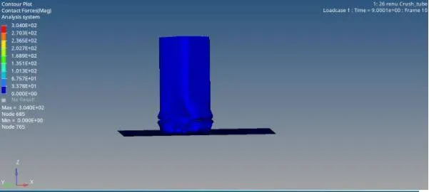
Contact force:
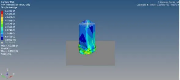
Von mises stress:
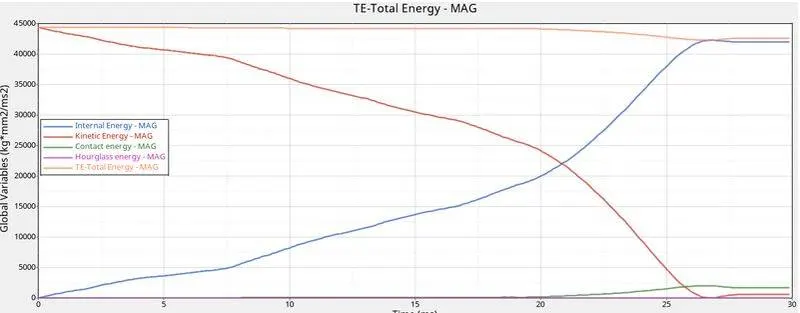
-The energy plot graph for the above simulation is as follows:
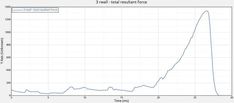
-The rigid wall force plot graph for above simulation is as follows:
CASE 3:
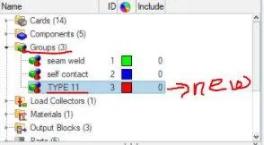
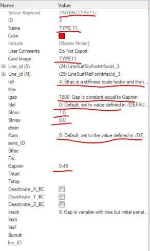
-In case 3 we will have to create a new type contact which (type 11) before running the simulation and this can be done by using the model browser option>click on the group>create.select the card as type 11 and we have to give the below inputs as follows:
1)lstf = 4 (Gap for stifness definition)
2)lgap = 1000 (It is the gap between master and slave node)
3)ldel = 0 (it is the node and segment deletion flag)
4)stmin = 1 (it is the minimum stifness value which can be used only if lstf value not equal to 1)
5)stmax=0 (it is the maximum stiffness value which can be used only if lstf value not equal t 1)
6)lform=0 (they are friction penalty fromulation type,here in our case it us 0)
7)Fric=0.25 (It is a model which helps to predict the dierection and magnitude of friction force between two bodies with dey surface in contact)
8)Gapmin=0.45(it s the minimum gap for the impact to activate)
9)inacti=6 (It is the option to deactivate the stiffness).
-After giving the necessary changes to the value now we can run the simulation and save it in a seperate folder as case 3.after simulation is runed sucessfully the output graphs and animation file is as follows:
-Energy and mass error:

-The animation of simulation is as follows:(.h3d file)
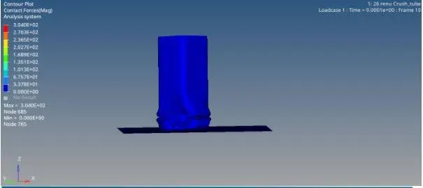
Contact force:
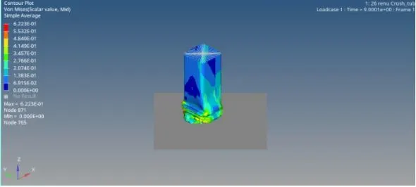
von mises stress
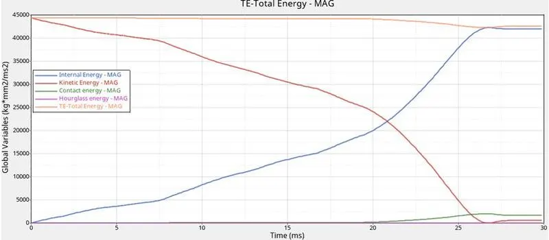
-The energy plot graph is as follows:
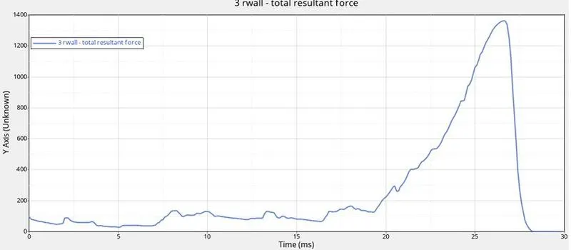
-The rigid wallforce graph is as shown below:
CASE 4:
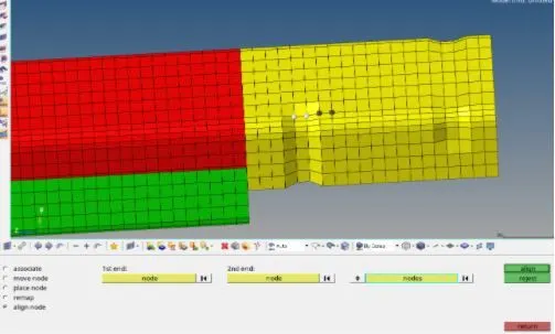
-Here we need to delete the notches and a plane mesh will be created in area of those notches before running the simulation.
-To delete the notches click on F2 inorder to delete the option panel.Now select the elements and click on delete entity and there by notches get deleted form the system.
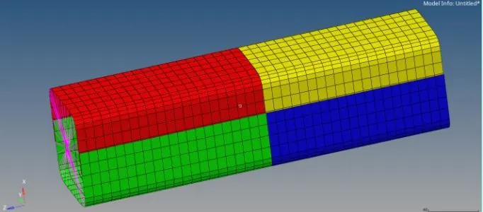
-Now to create a plane surface we need to go to main menu page>2D>ruled.Select nodes on first path and later second path and finally click on create.
-Now we need to delete the boundary conditions.To perfrom this operation go to Tab bar>slover>BCS now right click on BCS and click on delete.
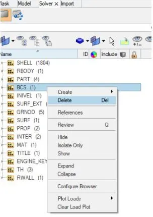
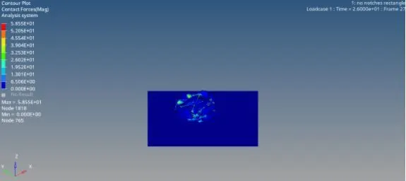
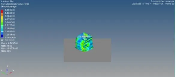
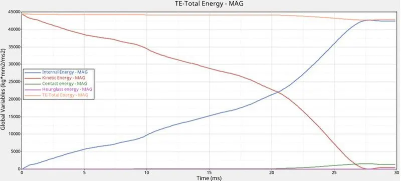
-To open the solver go to main menu bar>veiw>browser>hypermesh>solver.Now we run the simulation and save it in a seperate folder as case 4.Now the obtained output if energy ,mass error and graph plot will be as follows:

-Contact Force:
-Von Mises Stress:
-Energy graph plot:
-Rigid wall froce graph: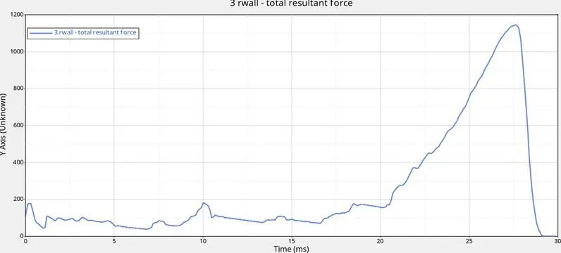
Case 5:
-In case 5 we need to create a new notch in middle of the crash tube which can be done by using a translate option.To do that we need to go to main menu page>tools>translate.
-Now select the nodes to be translated,set oreintation of the elements,give the magnitude as 4.094 and we need to click on translate -.
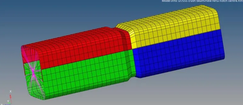
-Once when the notch is created the ,run the simulation and store it in seperate file as case 5.Now after the simualtion is runned we will get the output as follows:
mass and energy error cycle: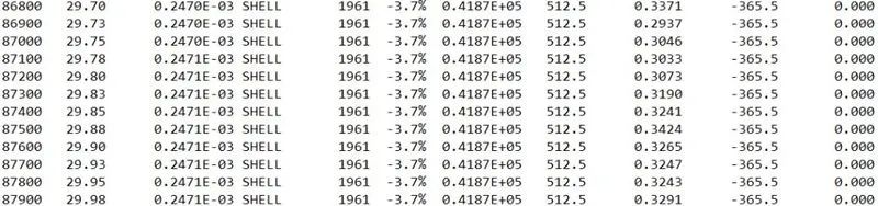
-Contact forces:
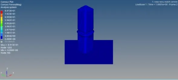
Von mesis force: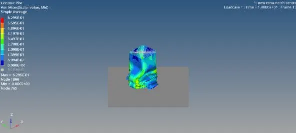
-Total energy graph:
-Rigid wall force graph:
Case 6:
-In this case we need to create a new nodes with notch only from opposing two faces by aling or translate option.
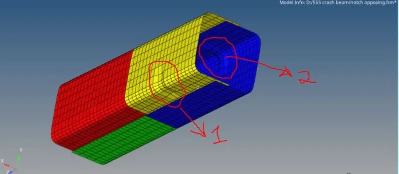
-To perform translate operation go to mainmenu page>Tools>translate.Select the node to translate,set the orientaion of elememts and click on translate + or -.
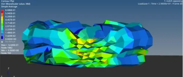
-Now we can run the simulation and store it in a seperate folder as case 6.After the simulation is completed we will get the output as follows:
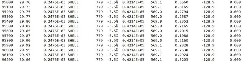
1)mass and energy error cycle:
-Contact force: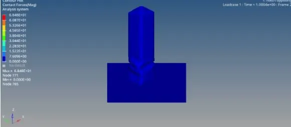
-Von mesis stress:
-The energy plot graph will be as follows: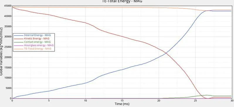
-Rigid wall forces will be as follows: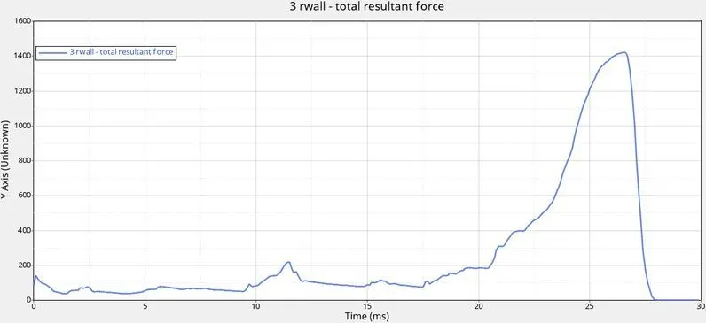
-Conclusion:
-Based on the observation we can say that energy is conserved in all the model which shows that our model has runned correctly without error.
-The main differemce between the model with notch and model without notch is on the impact it faces during the conditions we see the part not only crumbles but also gets bended from the area around the notch,where as in case the specimen without notch,we see failure only comencing in the point of impact.
-Force in the specimen with notch are higher compared to force in the specimen without notch or with only half notch which results in high stress in specimen with notch which can be confirmed with maximum stress value.when notch is being introduced the energy error will also be increased.
-As this is a simple simulation setup,we cannot obsereve much difference in the case1 and case 2(here we have given inacti value as 6).Hourglass energy in all the cases remains negligible which shows that there is no unwanted elemental behaviour also we can see very small spikes at end of the simulation when the crash tube is almost crushed towards itself this can identified and removed using finer mesh.
Result:
The simulation for different cases was runned succesfully and the output was also compared.