Assignment 4 - Material Modes in Radioss
Aim: To study of Elements behaviour under applied velocity and by changing material modes.
1. Total number of cycles, Energy error, mass error and simulation time.
Ans:
| Sl. No. | Type | No. of Cycles | Energy Error(%) | Mass Error(%) | Simulation Time (s) |
| 1 | LAW2_EPSMAX_FAILURE | 49380 | -0.3 to 1.3 | 0 | 92.87 |
| 2 | LAW2_EPSMAX_CACK | 49217 | -0.3 to 4.1 | 0 | 104.17 |
| 3 | LAW2_EPSMAX_NO_FAIl | 49408 | -0.3 to 0.8 | 0 | 98.46 |
| 4 | LAW2 | 49304 | -0.3 to 1.1 | 0 | 97.96 |
| 5 | LAW1 | 47969 | -0.3 to 1.3 | 0 | 96.35 |
| 6 | LAW27 | 49508 | -0.3 to 0.8 | 0 | 106.17 |
| 7 | LAW36 | 53202 | -0.3 to -1.4 | 0 | 107.50 |
All simulations are done under Recommended properties for elements formulation:
Ishell =24 QEPH 4 nodes shells are best combination of cost and accuracy.
Ismstr=2 Full geometric nonlinearities (default)with possible small strain formulation activation in RADIOSS Engine.
Ish3n=2 Standard 3 noded shell (C0)with modification for large rotation(default)
N=5 Number of integration points set to 5 for accuracy bending.
Ithick=1 Thickness change is taken into account for accuracy.
Iplas=1 Iterative plasticity for good accuracy.
Import the runname_0000.rad file in to hypermesh:
To import file,
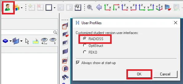
a. change user profile to radioss Because we are using slover as Radioss
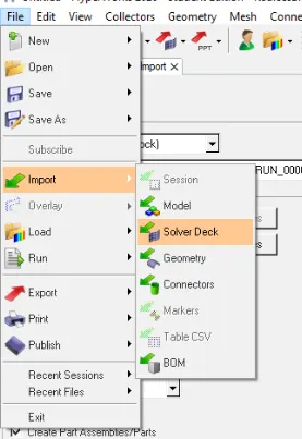
b. File>Import>Solver deck. we can see the new tab where options are available for browse file. Browse the file FIRST_RUN_0000.rad (starter input file),
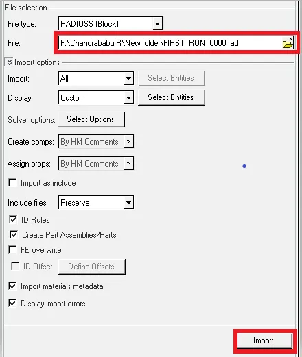
Now we are going to study on material models
2. Notice the animation of all 5 and describe the animations in brief on the basis of whether the elements are being deleted or cracked.
1. LAW2_EPSMAX_FAILURE (Case 1): This case is carried out by using M2_PLS_JOHNS_ZERIAL (MAT/LAW2/(PLAS_JOHNS)
What is MAT/LAW2/(PLAS_JOHNS?
This law represents an isotropic elasto-plastic material using the Johnson-Cook material model. This model expresses material stress as a function of strain, strain rate and temperature. A built-in failure criterion based on the maximum plastic strain is available. Stress-Strain curve for elastoplast is shown in the figure below
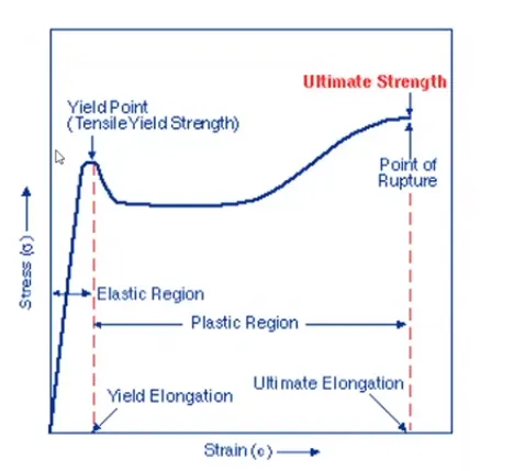
In LAW2 there are three parts to the stress calculation.
`sigma` Stress
`epsilonp` Plastic strain
`epsilon` Strain rate
`epsilono` Reference strain rate
a Yeild stress
b Hardening modulus
n Hardening exponent
c Strain rate
There are two ways to input material parameter in LAW2
for Influence of plastic strain.
1. Iflag=0: Classic input for Johnson-Cook parameter a , b , n is active
σ=a+b⋅εpn
2. Iflag=1: New, simplified input with yield stress, UTS (engineering stress), or strain at UTS. With this new input, you will need yield stress ( σ y ), Ultimate tensile engineer stress (UTS) and engineer strain ( ε U T S ) at the necking point. With this new input, Radioss automatically calculates the equivalent value for a , b and n .
For Influence of strain rate
Strain rate has an effect on material character such as crash performance in tensile or in fracture. In Johnson-Cook, yield stress is affected directly by the strain rate, which is given by
σ = ( a + b ⋅ ε p n ) ( 1 + c ln(ε/ε 0) )
Yield stress increases with increasing in the test strain rate. With the strain rate coefficient, c , we can notice an increase of yield stress. No effect of strain rate also possible only if c =0; or with ˙ ε 0 = 10^30 or ε ≤ ε 0.
for better understanding see the natural logarithm
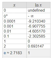
To eliminate the effect of the strain rate, you can either set the value of c equal to 0 or the reference strain rate ( ε 0 ) can be set equal to 10^30. There is no effect of strain rate when ε is less than ε 0 .
For Influence of temperature change
Yield stress decreases with increasing temperature. In LAW2 influence is considered with term (1−T^m)
Now let's see the case 1
In this case model is runt as it is i.e default value using aluminum material with M2_PLS_JOHNS_ZERIAL model. Punch is thrown on the plate with velocity.
here Iflag=0: Classic input for Johnson-Cook parameter a , b , n is active
σ=a+b⋅εpn
'a' is the yield stress which is read from the material test and converted to true stress.
When `epsilonp` reaches the value of `epsilonp max` in one integration point, then based on the element type The corresponding shell element is deleted. we can see that elements which are failing are automatically deleted. in the fig 1.1 show the elements are deleted which is strain is greater than or equal to max strain stain. We have strain 0.152 is the max. Also we can see the initial and final stage for strain rate with graphs.
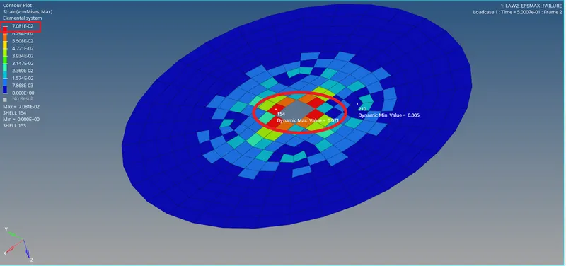
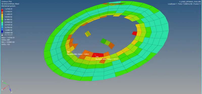
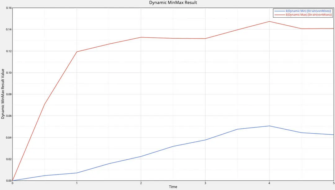
Fig.1.1: Case 1
In the fig 1.2 we can see simulation for case 1 and fig1.3 energy Graphs
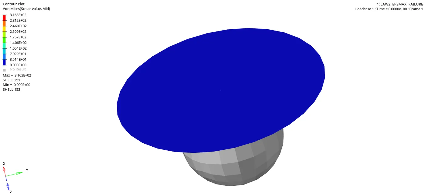
Fig.1.2: simulation
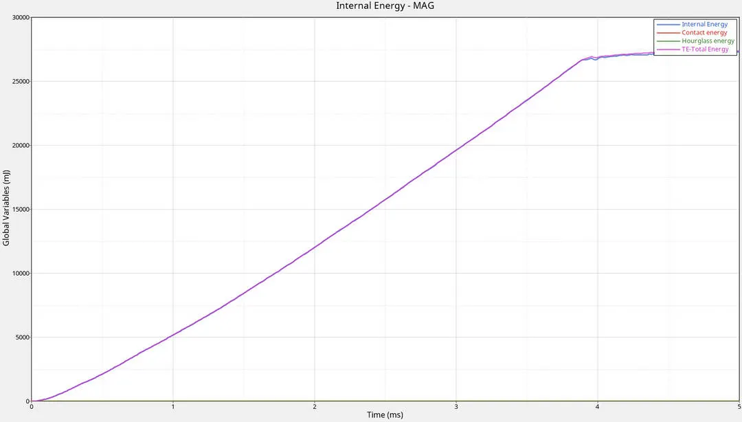
Fig.1.3:Energy
In the above graph
1. Contact energy and hourglass energy is constant because both are controlled by elements formulation. Here hourglass is controlled by Physical stabilization i.e changing material level in ISHELL is 24 QEPH Shell formulation.
2. Total and internal energies are increasing w,r,t to time until the component reaches complete failure, after that its constant wrt to time. because at the initial stage we have maximum velocity,Kinetic energy is directly proportional to the Velocity. so kinetic energy is max at initial stage after hitting the KE is observed by plate so internal energy increase until the component reaches complete failure after that there is no energy observed (internal energy ΔU = q+w)
we have Total Energy = Internal Energy + Kinetic energy + External Work, Total energy should be constance but here due to Imposed Motion the Total energy follows the external works,
the max von mises stress is 316.3 GPa
2. LAW2_EPSMAX_CACK (Case 2): Describes the failure criteria by Johnson-Cook failure model failure strain as a function of stress.
Here changing the Failure card as mentioned above values
Ifail_sh=1
Dadv=1
Ixfem=1
If Ifail_sh=1In this case, the whole element thickness is considered as a single layer. The failure criterion is calculated in each integration point, but only one single crack can appear in this element
this is for shell elements if Ifail_sh is 1 then elements will delete or crack depending on Ixfem
Dadv=1
Criterion for the crack advancement (Only active if with Ixfem =1)
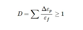
Ef is Plastic failure strain
Ep is Plastic strain
Ixfem=1
Element cracked, if
this element has no failed neighbors and D > 1, then in this case, new crack initialization in element.
Element deleted, if a second crack arrives to the same element.
In the figure we can see the crack before deleting elements. initial and final pics are shown in the figure 2.1

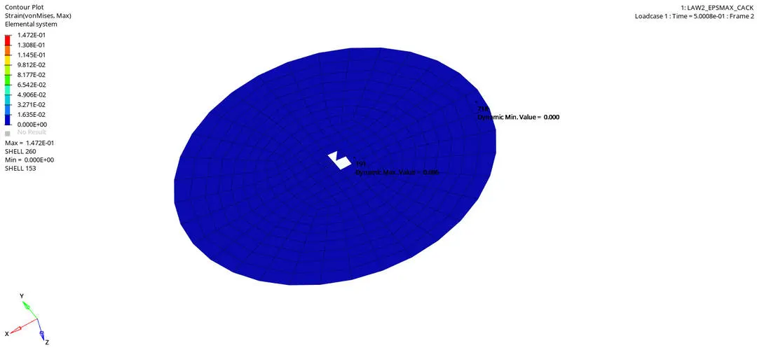
Fig.2.1: Case 2
In the fig 2.2 we can see simulation for case 2 and fig2.3 energy Graphs
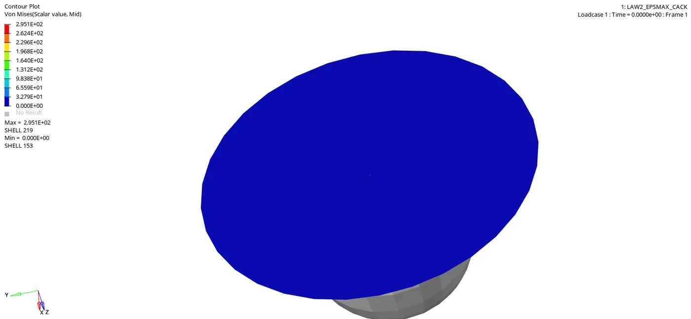
Fig.2.2: simulation
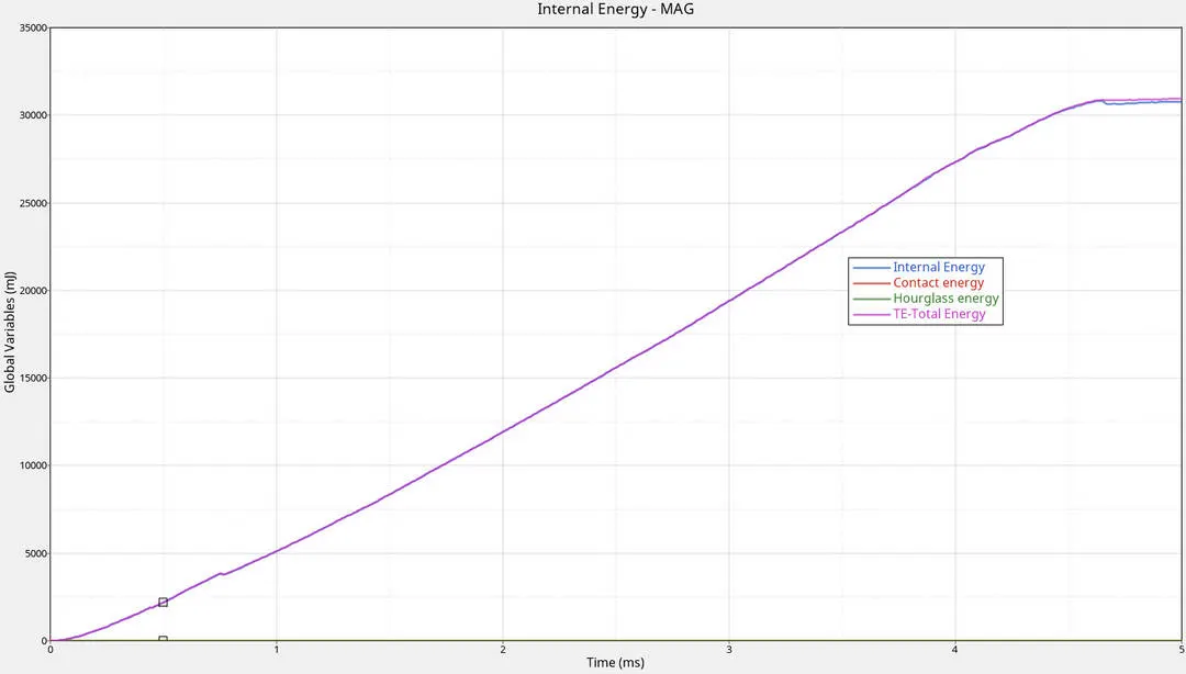
Fig.2.3: Energy
In case 2 is the same as that of case 1 but here we can see crack before deleting elements. The max von mises stress is 295.1 GPa. See the energies are more compare to case 1
3. LAW2_EPSMAX_NO_FAIL(Case 3): Here Deleting the failure card and checking the elements behaviour. There is no failure card so we can't see the crack in elements. its same as that of case 1 but here failure of elements are base on stress
We can see the difference between case 1 and 2 with stress.
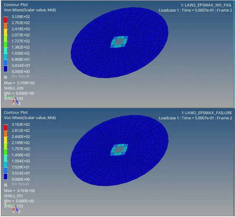
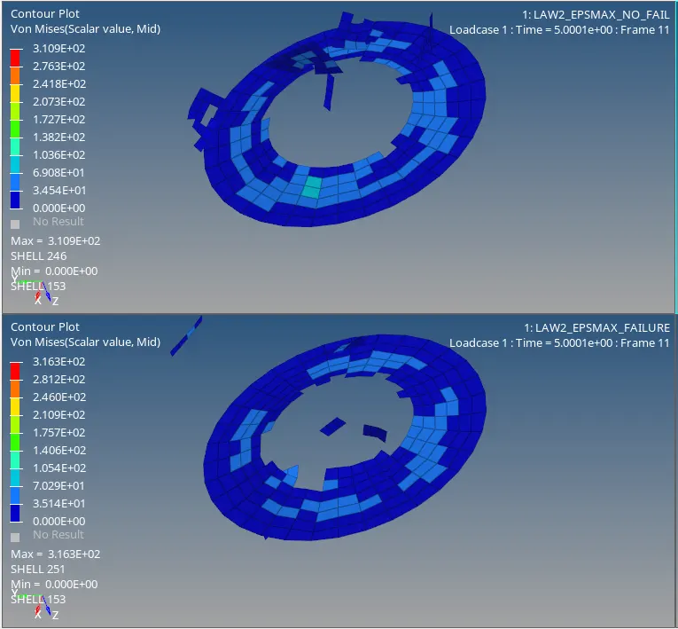
In the fig 3.2 we can see simulation for case 3 and fig3.3 energy Graphs
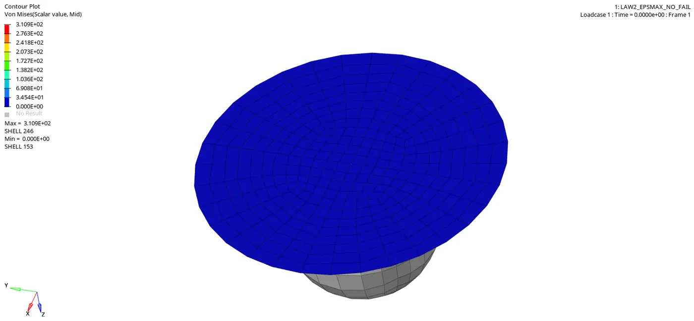
Fig.3.2: simulation
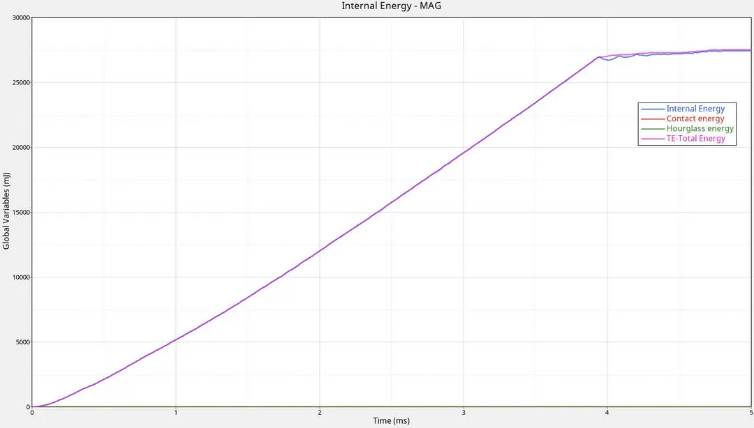
Fig.3.3:Energy
In case 3 is the same as that of case 1 but here we can see crack before deleting elements. the max von mises stress is 310.9 GPa
4. law2 (case 4):
In this case model is runt as it is i.e default value using aluminum material with M2_PLS_JOHNS_ZERIAL model. Punch is thrown on the plate with velocity.
here Iflag=0: Classic input for Johnson-Cook parameter a , b , n is active
σ=a+b⋅εpn
'a' is the yield stress which is read from the material test and converted to true stress.
When `epsilonp max` is deleted or set to default i.e 10^3. so deleting elements are the default value. we can see the stress (325.6MPa) and strain (0.58)
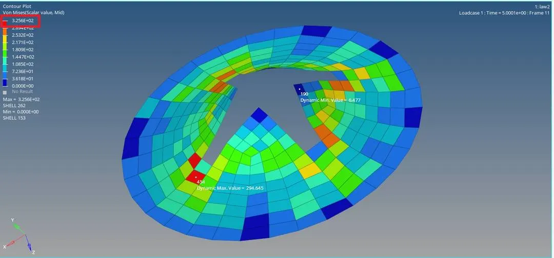
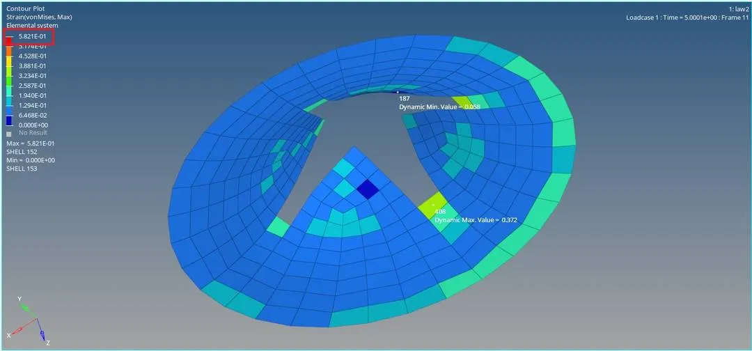
In the fig 4.2 we can see simulation for case 4 and fig4.3 energy Graphs
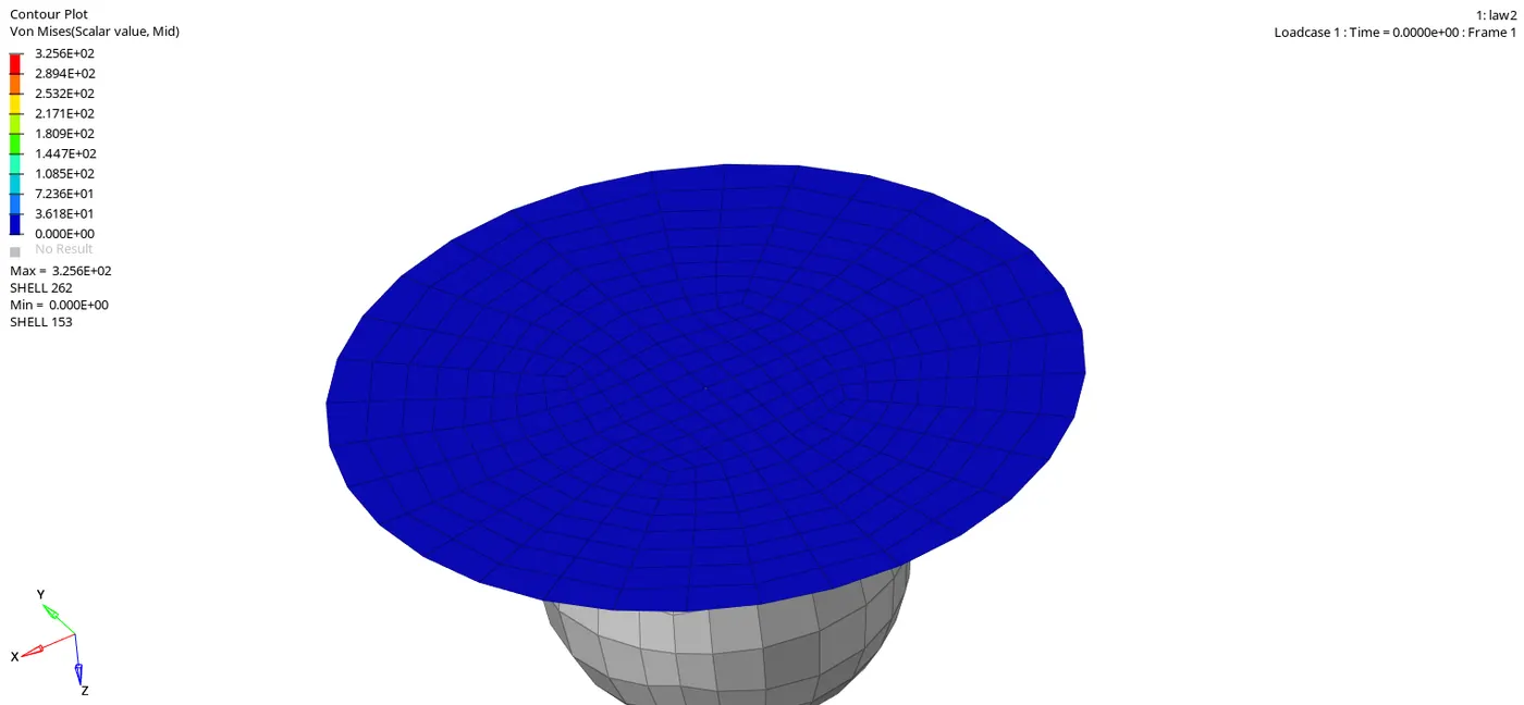
Fig.4.2: simulation
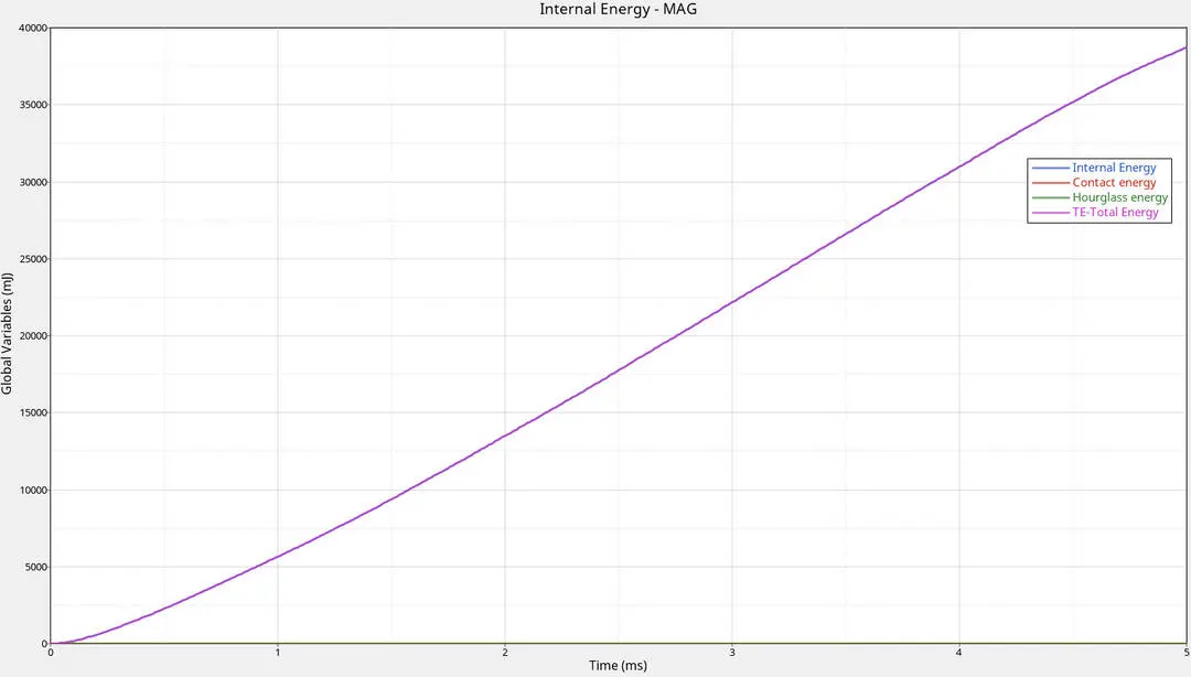
Fig.4.3:Energy
Because there is no condition on plastic strain max, elements are taking max real load so total energy and internal energy are increasing by taking Kinetic energy.
5. LAW1_M_ELAST (case 5):
This law defines an isotropic, linear elastic material using Hooke's law. This law represents a linear relationship between stress and strain
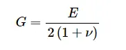
This material law is used to model purely elastic materials. The material stiffness is determined by only two values the Young's modulus (E), and Poisson's ratio (ν), The shear modulus (G) can be computed using E and ν , as
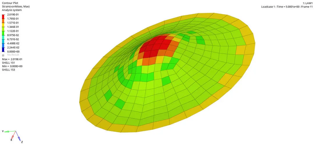
Because of linear elastic material using Hooke's law all the elements are under elastic limit so no elements are failing. we can see the stress( 1.1X10^4 MPa) and stain(0.209) below
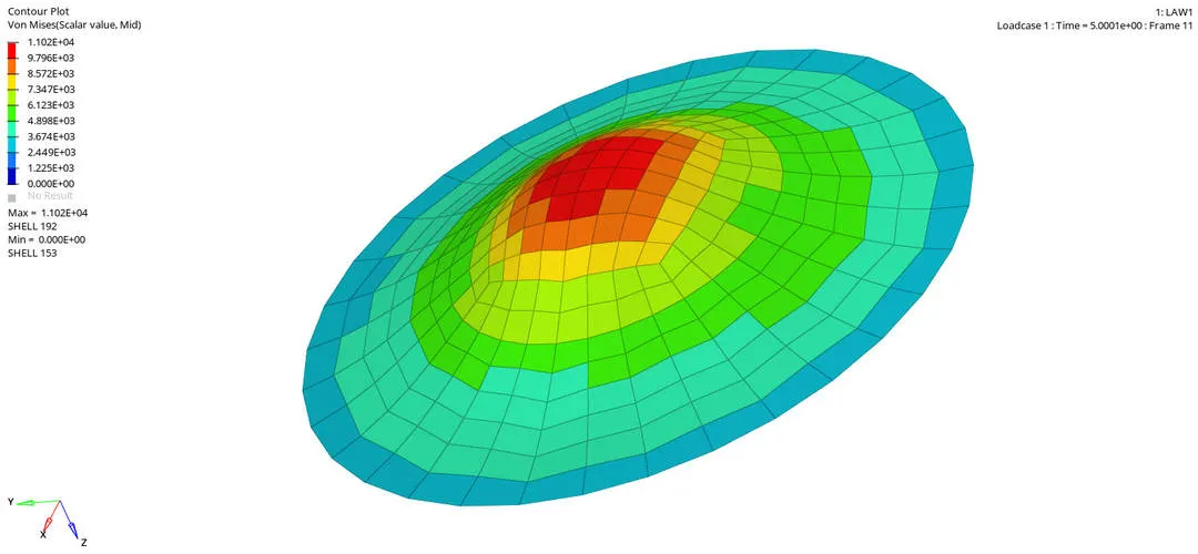
In the fig 5.2 we can see simulation for case 5 and fig5.3 energy Graphs
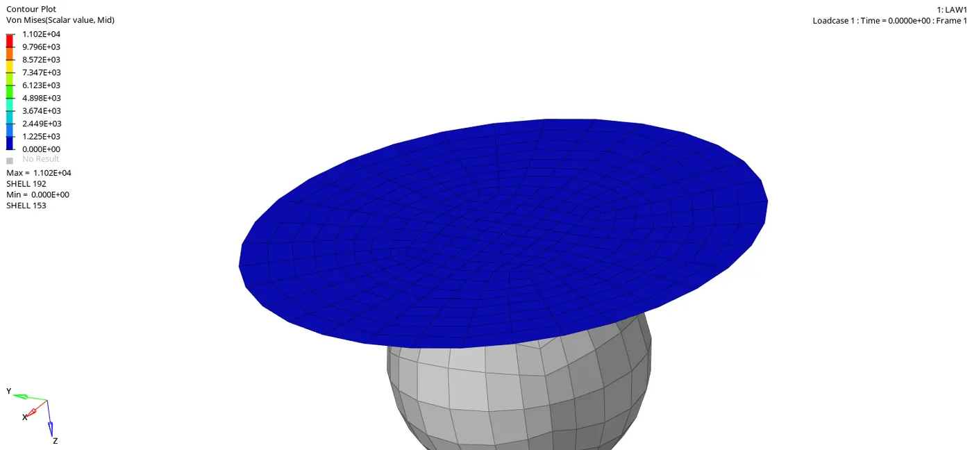
Fig.5.2: simulation
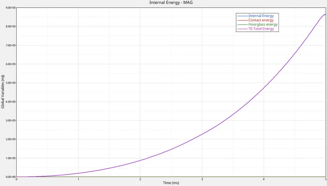
Fig.5.3:Energy
Total and internal energies are increasing w,r,t to time until the component reaches max max string for the given velocity without fail, because at initial stage we have maximum velocity,Kinetic energy is directly proportional to the Velocity. so kinetic energy is max at the initial stage after hitting the KE is observed by plate so internal energy increases until the component reaches max max string for the given velocity without fail.
6.LAW27 (case 6):
This law combines an isotropic elasto-plastic Johnson-Cook material model with an orthotropic brittle failure model. Material damage is accounted for prior to failure. Failure and damage occur only in tension. This law is applicable only for shells.
In this law elements are deleted at Maximum tensile strain.
In the fig 6.2 we can see simulation for case 6 and fig6.3 energy Graphs
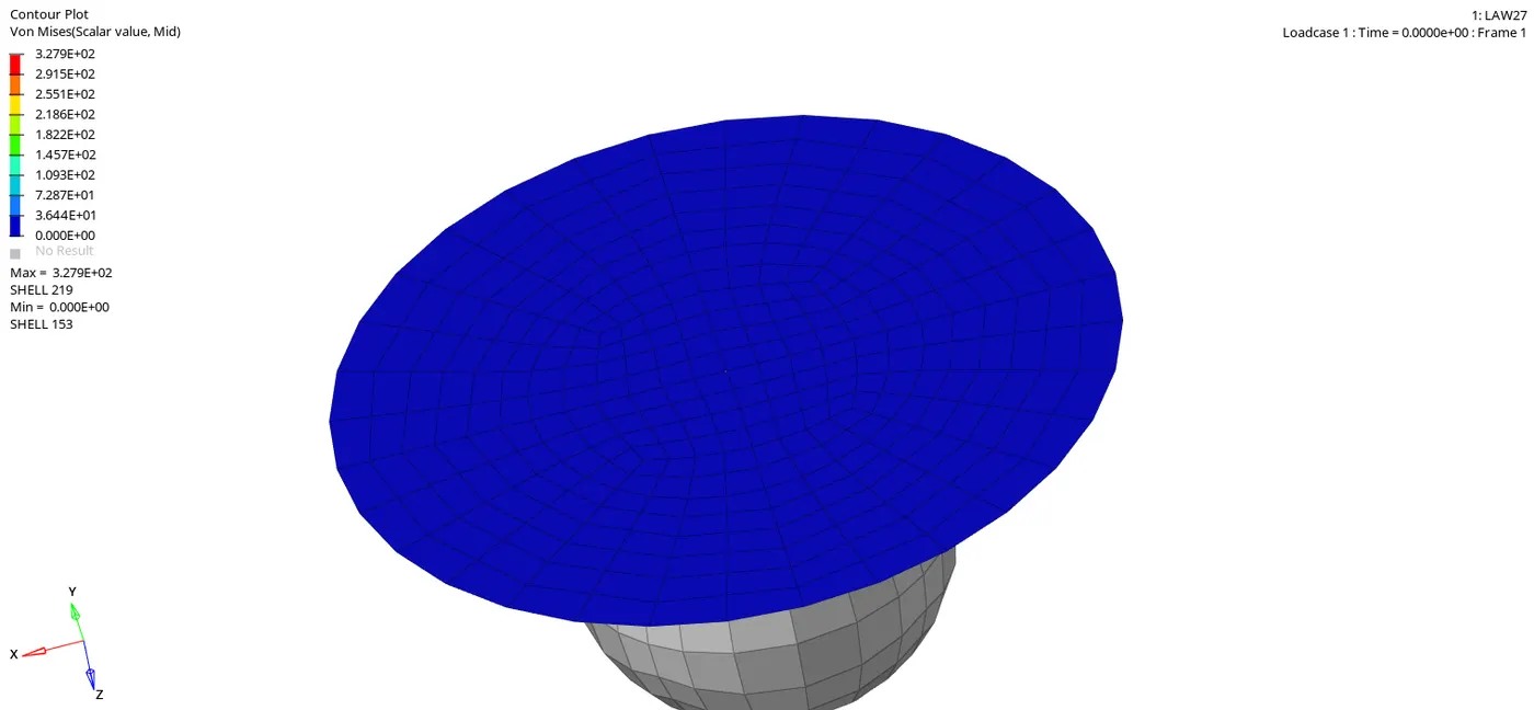
Fig.6.2: simulation
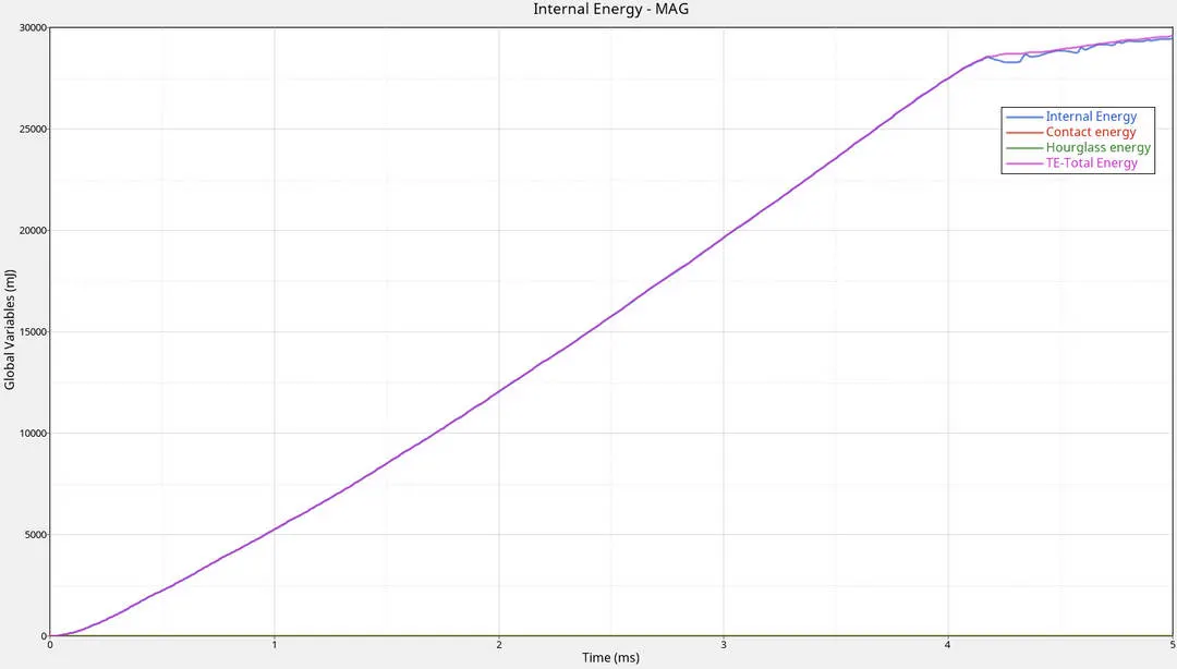
Fig.6.3:Energy
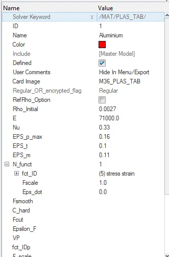
LAW36 (Case 7) /MAT/LAW36 (PLAS_TAB): This law models an isotropic elasto-plastic material using user-defined functions for the work-hardening portion of the stress-strain curve (for example, stress vs. plastic strain) for different strain rates.
Input the date for Initial density, Young's modulus, Poisson's ratio, Failure plastic strain, Tensile failure strain at which stress starts to reduce, Maximum tensile failure strain at which the stress in element is set to zero and Number of functions
This is a tabulated law; therefore, the true stress versus plastic strain function can be directly used. The rupture phase can be simulated by adding points to this hardening function.
we can use is different strain rate
Go to curves>create >new an enter the values for stress and strain shown in the fg bellow
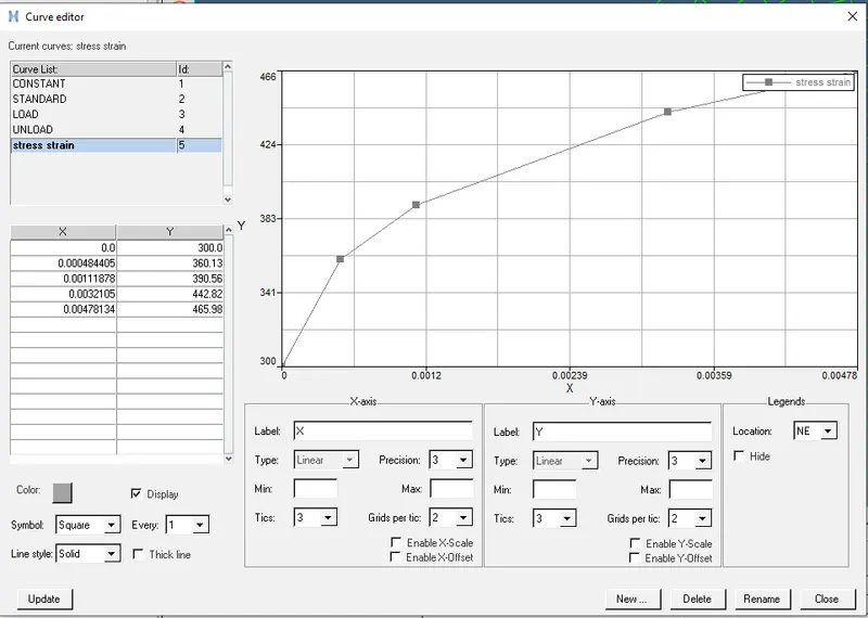
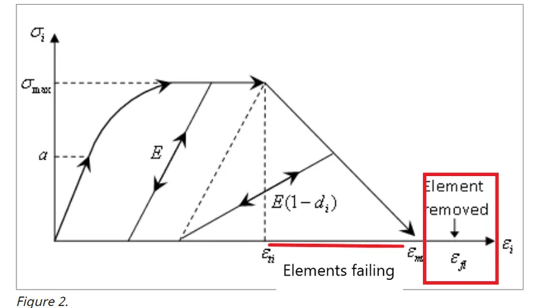
LAW36 has four damage and rupture parameters
EPS_p_max is the maximum plastic strain for the element deletion for any loading condition like tensile, shear or compression
EPS_t is the beginning of the tensile damage. from this point the stress value defined in the curve is reduced by the factor

EPS_m is the end of the damage. the stress value is null but the element is not deleted.
EPS_f is the tensile failure strain value for element deletion
In the fig 7.2 we can see simulation for case 7 and fig7.3 energy Graphs
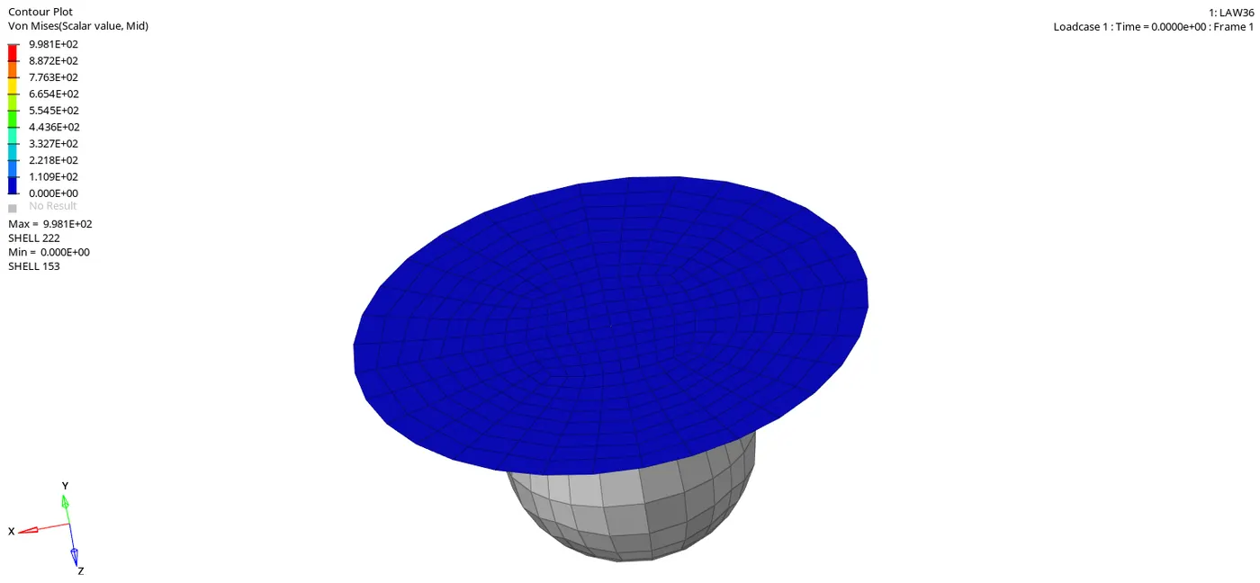
Fig.7.2: simulation
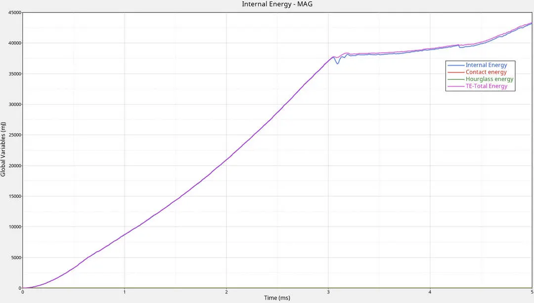
Fig.7.3:Energy
Total and internal energies are increasing w,r,t to time until the component reaches complete failure, after that its slightly increasing wrt to time. because at the initial stage we have maximum velocity, Kinetic energy is directly proportional to the Velocity. so kinetic energy is max at the initial stage after hitting the KE is observed by plate so internal energy increases until the component reaches complete failure.
4.Based on all the results, which case would represent the on-field
Law 36 case 7 is on field because we can get accurate results by manual input of stress and strain curves with different strain rate