Assignment 3
AIM: To simulate the crash beam file using Hypermesh and plot the results.
KEYWORDS: Engine run time, Energy error, mass error, Hourglass, Von mises stress, etc.,
SOFTWARE: Hypermesh
OBJECTIVE:
1.Using the crash beam file , change the run time to 55 ms.
2. Change the number of animation steps during simulation to a minimum of 25 and maximum of 60.
3. Run the base simulation without any modification to element properties.
4. At the end of the simulation, do the energy error and mass error checks and determine whether results would be acceptable.
5. If acceptable, Plot rigid wall forces, internal energy, hourglass energy, contact energy, total energy of the simulations.
6. Change all the shell elements properties to recommended properties, save this as separate, rad files and run the simulation.
7. Follow steps 5 and 6.
8. Create a brief report comparing all the results from steps 5 and 6 for both simulations.
9. Conclude the results if there is a change or not.
INTRODUCTION:
Altair RADIOSS is a multidisciplinary finite element solver developed by Altair Engineering. It can solve both linear and non-linear problems. It is a finite element solver using implicit and explicit integration schemes for the solution of engineering problems, from linear statics and linear dynamics to nonlinear transient dynamics and mechanical systems. This multidisciplinary solver enables designers to maximize performance related to durability, NVH, crash, safety, manufacturability, and fluid-structure interaction, in order to bring products to market faster. 'RADIOSS’ analysis capabilities for linear and non-linear finite element analysis, sheet metal stamping, and multi-body dynamics are accessible via two input formats.
While working with 1D elements, the following element types:
1. CROD
2. CBAR
3. CBEAM
In brief, CROD elements support (allow) tension and compression only, whereas CBARS and CBEAMS
allow bending as well. A CBAR element is a kind of simplified CBEAM element and should be used
whenever the cross-section of the structure and its properties is constant and symmetrical. The CBAR element requires that its shear center and the neutral axis coincide. Due to this requirement CBAR elements are not useful for modeling structures that may warp, such as open channel-sections. This limitation is not present in CBEAM elements. Thus, CBEAM elements are used to model more “complicated” geometries with varying cross sections. Important to note, in CBEAM elements the neutral axis and shear center are noncoincident. Overall, this type of element demands a deeper understanding of beam theory. Von Mises stress is a value used to determine if a given material will yield or fracture. The von Mises yield criterion states that if the von -Mises stress of a material under load is equal or greater than the yield limit of the same material under simple tension then the material will yield.
Here, crash beam file is given for simulation inorder to plot Internal energy, hourglass energy, contact energy, total energy, max von mises stress, time step, Normal force, Tangent force, and Energy error. Under-integrated elements are very familiar in crash worthiness. In these elements, a reduced number of integration points are used to decrease the computation time. This simplification generates zero energy deformation modes, called hourglass modes. The beam as 1 side is fixed to rigid wall and other side is defined as rigidity. When the force applied axially towards the rigid wall, the beam tends to deform and max. stress formed at the crirtical area, energy utilization, energy error, and time step etc., which is plotted below.
For the energy error, the error must be negative and decreasing (except for the first cycle or spring back stage). The error must be less than 15% at the end of computation (5% for good model). If the error increase a little, then decrease may be normal. If the error increases, this means that a problem has occurred. Then the error may grow to 99.9% with computation failure message.
So,ideally the error should be at most -15% and better to have -5% . The closer to 0% error the better. For QEPH shell formulation or fully integrated elements, the energy error can be slightly positive since there is no hourglass energy and the computation is much more accurate. An error of 1 or 2% will be acceptable. Otherwise any positive energy error means energy has been created which indicates a model issue.
( i ). Default Element Properties: For this simulation, the engine run time is 60 ms and the engine animation Tfreq is 1 and run the radioss file which creates the animation file in h3d format. The H3D format file is opened in hyperview which shows the animation till engine run time. Hypergraph 2D is used to plot the global variables which shows the stress, deformation and energy variation.
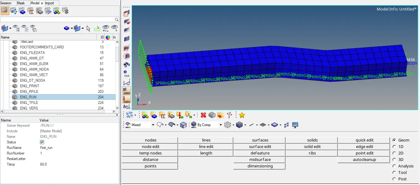
Fig 1: Engine run time with Actual model
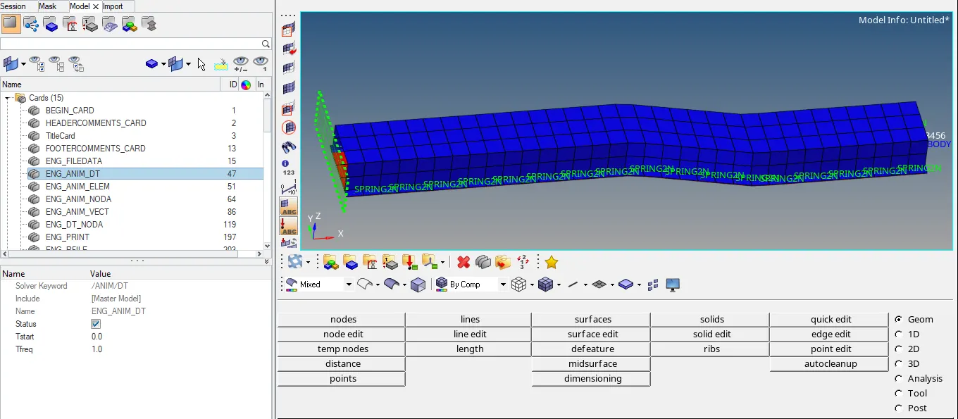
Fig 2: Engine Animation file
( ii ). Modified Element Properties: For this simulation, the engine run time is 55 ms and the engine animation Tfreq is 1.25 (by considering animation step as 44) and run the radioss file which creates the animation file in h3d format. The H3D format file is opened in hyperview which shows the animation till engine run time. Hypergraph 2D is used to plot the global variables which shows the stress, deformation and energy variation.
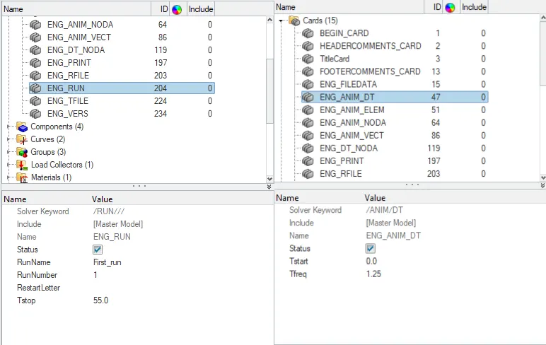
Fig 3: Engine run time & Engine Animation file
Recommended properties:
The QEPH shell is a new improved element with respect to QPH,QPPS. The improvements will be explained. QEPH (Quadrilateral ElastoPlastic Physical Hourglass Control) element With one-point integration formulation, if the non-constant part follows exactly the state of constant part for the case of elasto-plastic calculation, the plasticity will be under-estimated due to the fact that the constant equivalent stress is often the smallest one in the element and element will be stiffer. Therefore, defining a yield criterion for the non-constant part seems to be a good ideal to overcome this drawback.
The modified element properties are highlighted in yellow color and applied in the simulation which is shown in below figure.
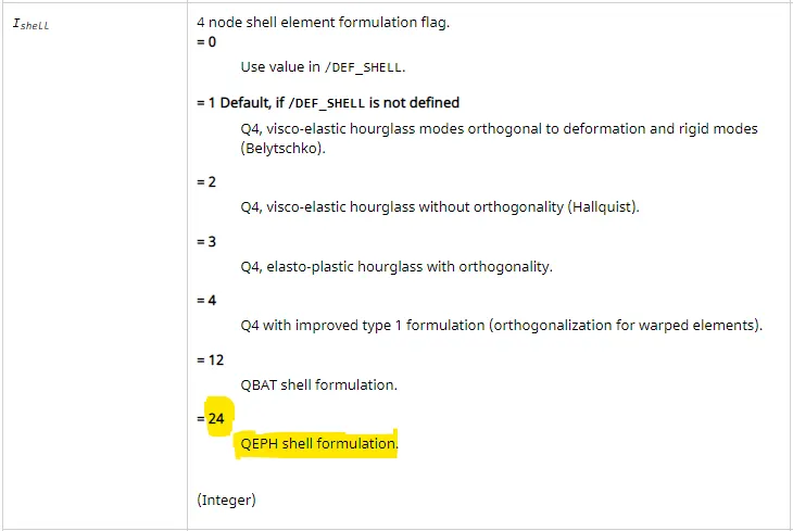
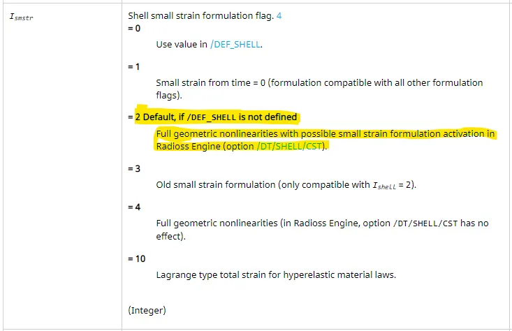
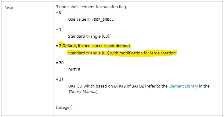

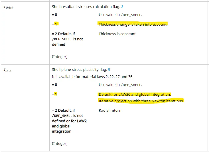
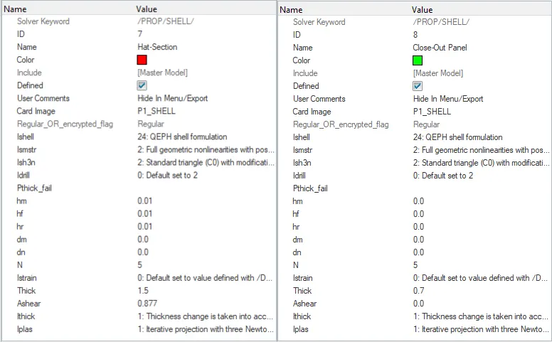
Fig 4: Recommended Element Properties
RESULTS WITH COMPARISON:
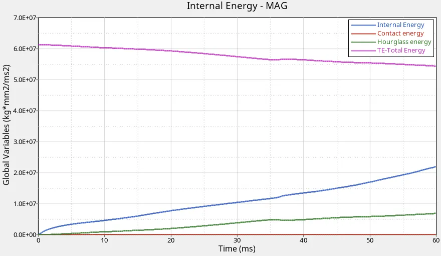
Fig 5(a): Energy Graph of default property
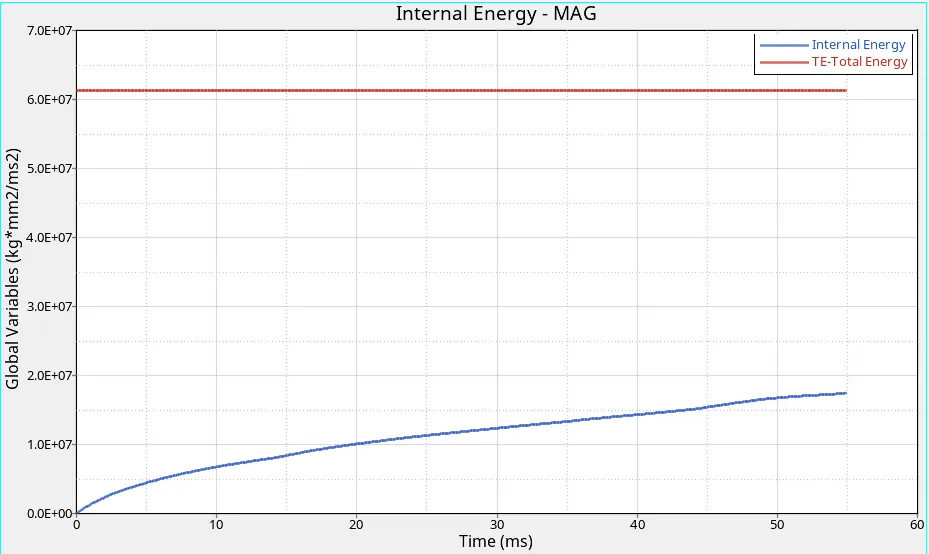
Fig 5(b): Energy Graph of modified property
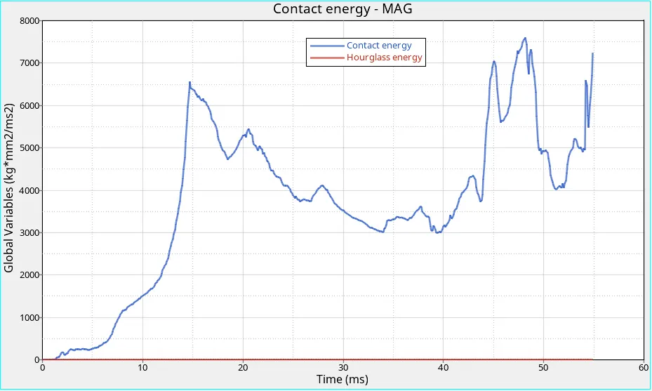
Fig 5(c): Energy Graph of modified property
Energy variation like Internal energy, contact energy, hourglass energy and total energy are varied wrt time according to the shell element properties which is shown in Fig (1) & (2) is default property and Fig (3) shows the recommended element properties. The energy graphs for default and recommended properties are shown in Fig 5 (a) , (b) & (c). There is no hourglass energy formed in modified property whereas there is little variation in default property.
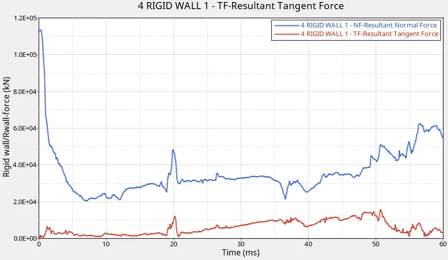
Fig 6(a): Rigid Wall Force Graph of default property
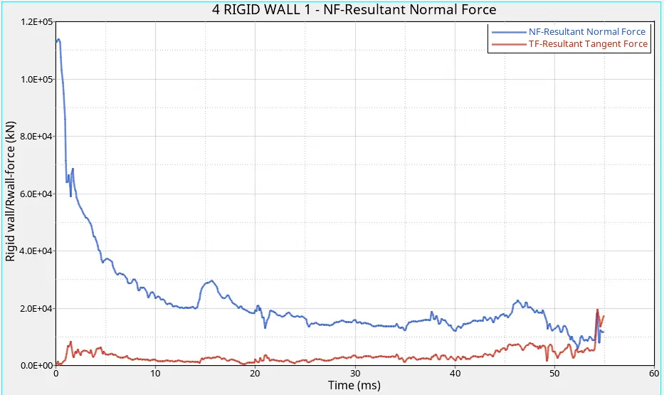
Fig 6(b): Rigid Wall Force Graph of modified property
The Figure 6 (a) & (b) shows the Rigid wall force of Normal force & Tangent Force wrt time. the force variation on the wall in default property is more where as less in recommended property.
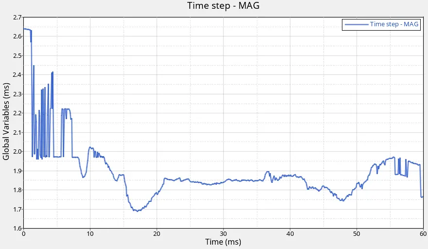
Fig 7(a): Time step Graph of default property
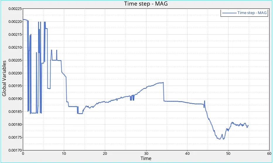
Fig 7(b): Time step Graph of modified property
The Figure 7 (a) & (b) shows the time step variation wrt time. The time step taken is more in default property because of hourgalss formed which increases the integration point where as less time taken in recommended property because of no hourglass formed.
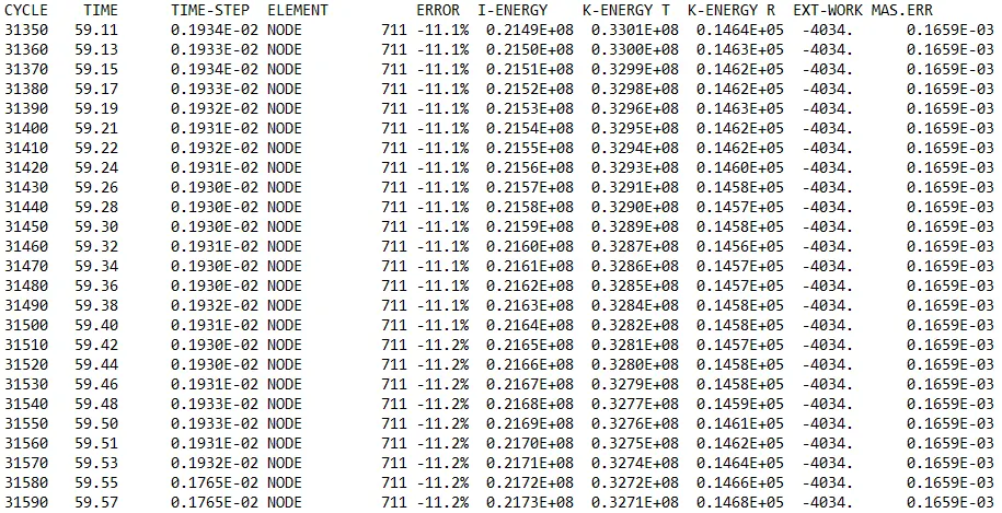
Fig 8 (a): Energy error of default property
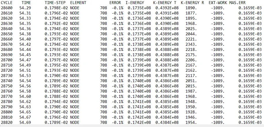
Fig 8 (b): Energy error of recommended property
The Figure 8 (a) & (b) shows the energy error of default and recommended property. In which the energy error is more in default (-11.2 %) where as (-0.1 %) in recommended property. For QEPH shell formulation or fully integrated elements, the energy error can be slightly positive since there is no hourglass energy and the computation is much more accurate.
CONCLUSION:
1. The beam file (0000.rad) is imported to the Hypermesh and run the analysis by radioss.
2. After the analysis, h3d animation file is created in a default folder.
3. By importing the h3d animation file to hyperview and run the simulation to notedown the von mises stress.
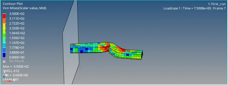
4. The Max von-mises stress for Default and recommended property is 350 N/mm2.
. By using the Hypergraph 2D, plot rigid wall forces, internal energy, hourglass energy, contact energy, total energy of the simulations.
DRIVE_LINK:
https://drive.google.com/drive/folders/1xmeZdwn6yEqOBYadpiQFS5uQIX2ysWpv?usp=sharing