Assignment 3-2D Element Formulation Challenge
Refer link : https://skill-lync.com/student-projects/2d-element-formulation-challenge
AIM: To run the simulation of a crash beam model ith base simulation (default values) followed by improved shell element properties (recommended properties)
PROCEDURE:
Objective 1. Using the crash beam file from the previous assignment, change the run time to 55 ms.
- Firstly, we need to import the Radioss file in solver deck, to do so Go to File>>Import>>Solver deck. Select the starter file ending with '0000.rad'.
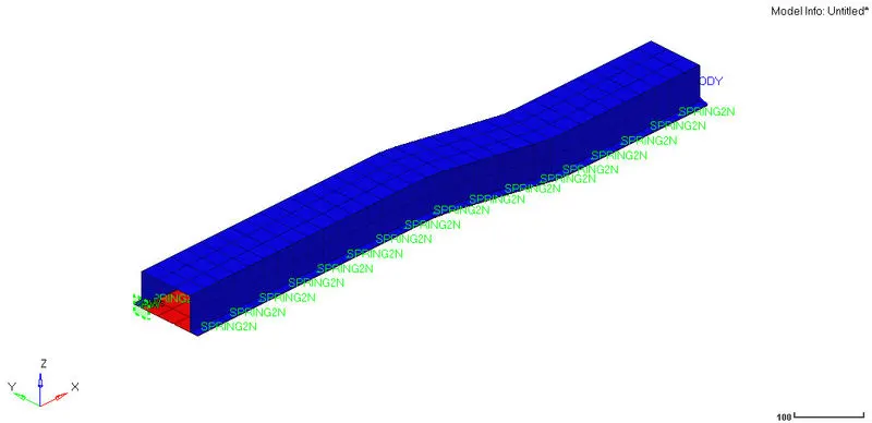
- Now, once the file is imported and the model is visualize, we can begin with assigning the runtime to 55ms. In order to assign value, go to the model tree parameter under cards we have Run_Engine. We select the entity and the value of 55 ms is assigned.
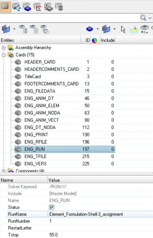 Changing the Run time
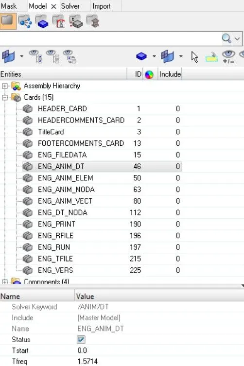
Objective 2. Change the number of animation steps during simulation to a minimum of 25 and maximum of 60.
- We again select the cards entity in tree model, there under ENG_ANIM_DT we assign T freq as 1.5714, because we have select 35 between 25 & 60 and divide it with run time as 55.
Objective 3. Run the base simulation without any modification to element properties.
- We run the base simulation with keeping the element properties as default.
- We proceed for simulation by hitting the Analysis tap and click Radioss.

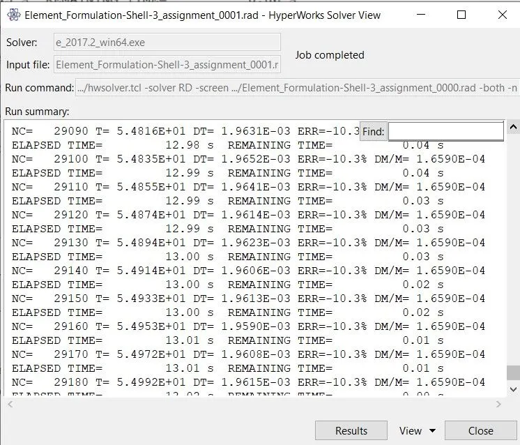
- A Tab appears on screen which tells about simulation run time, along with energy error %,time .
- Once the simulation is done, we acquire the desired parameters such as stress, strain & deformation values along with the various energy graphs, along with the generated files for animation and timestep which can be seen.

- Once the simulation run through, we switch to hyperview, and the file format 'h3d' is imported.
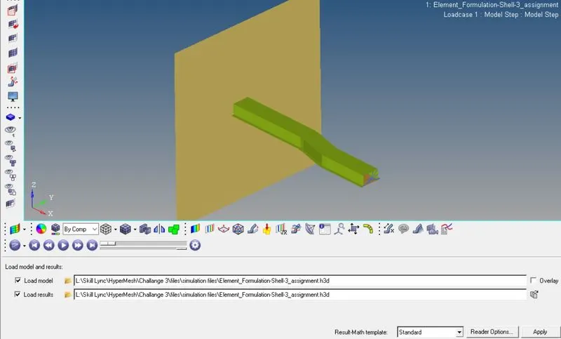
- Later, we can switch to hypergraph to visualize the Internal energy graph, rigid wall, total energy & Hourglass energy.
- Following are the Von Misses stress, deformation & Stress
OBJECTIVE 4. At the end of the simulation, do the energy error and mass error checks and determine whether results would be acceptable. 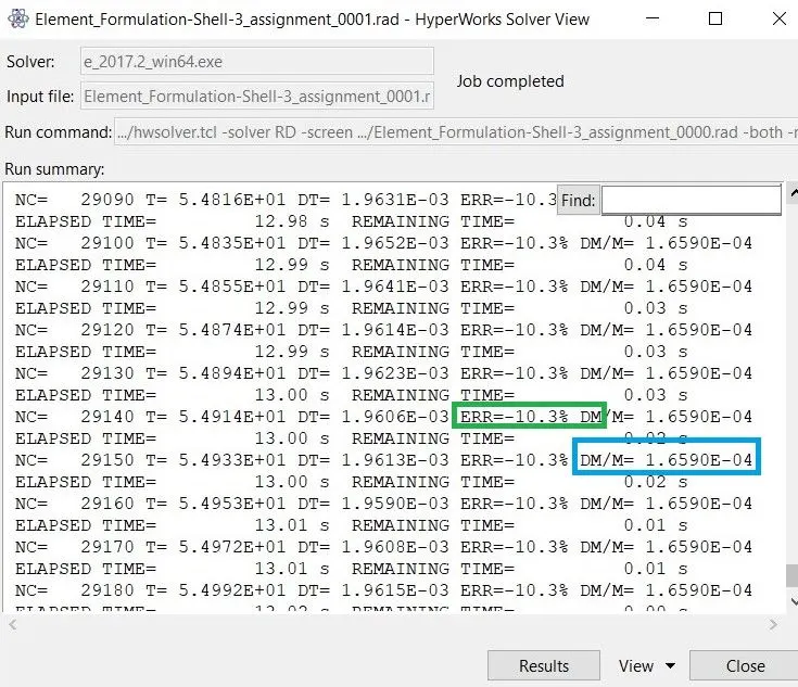
- From above, it can be seen that the model has undergone analysis and obtain a maximum value of energy error as -10.3%
- While, the mass error is 1.659 which is acceptable since the range varies from -15% to +5%.
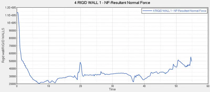
OBJECTIVE 5. If acceptable, Plot rigid wall forces, internal energy, hourglass energy, contact energy, total energy of the simulations.
Now, we can switch to hypergraph to visualize the Internal energy graph, rigid wall, total energy & Hourglass energy. 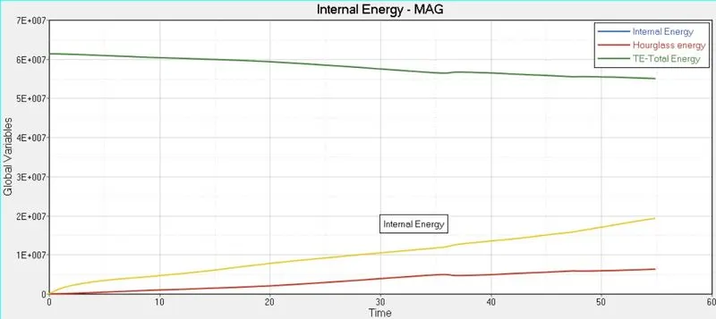
OBJECTIVE 6. Change all the shell elements properties to recommended properties, save this as separate, rad files and run the simulation.
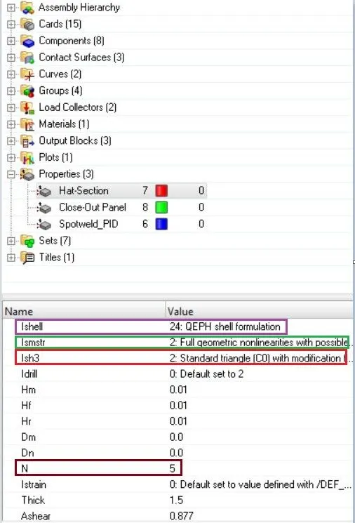
- Now, we import the same model along with the earlier assigned values butapplying the shell elements properties as follow, to visualize the results
| Parameters | Comment | |
|
Ishell =24 |
QEPH 4 nodes shells are best combination of cost and accuracy. | |
|
Ismstr=2 |
Full geometric nonlinearities (default)with possible small strain formulation activation in RADIOSS Engine. | |
|
Ish3n=2 |
Standard 3 noded shell (C0)with modification for large rotation(default) |
|
| N=5 | Number of integration points set to 5 for accuracy bending. | |
|
Ithick=1 |
Thickness change is taken into account for accuracy. |
|
|
Iplas=1 |
Iterative plasticity for good accuracy. |
- after assigning the values the simulation is run, we can then visualize the obtained results from the appeared window job complition status.
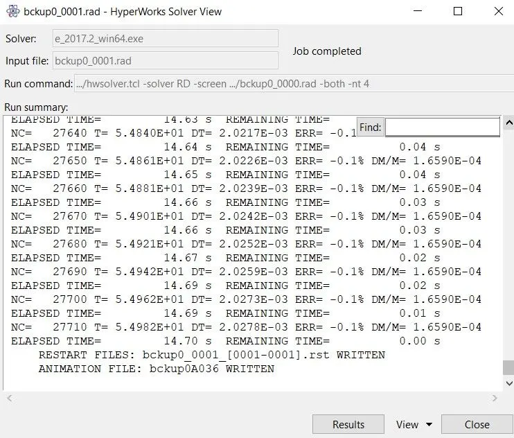
- As per earlier, we can see a different values in energy error% & mass error
- Energy error is still acceptable which is -0.1%, however it is still in range between -15% to +5%
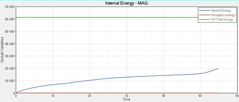
Ploted graphs can be seen as follows,
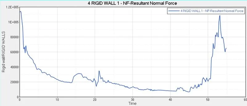
Animation can be visualize as follows,
We can even compair the results as follows,
By ploting the two different graphs in same plot for sake of simplicity for comparision purpose.
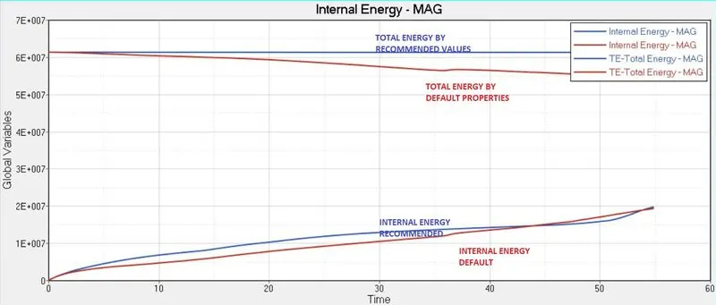
Comparision-
|
ATTRIBUTE |
DEFAULT PROPERTIES |
RECOMMENDED PROPERTIES |
|
ENERGY ERROR |
-10.3% which is acceptable |
-0.1% is great, still near to zero |
|
HOURGLASS ENERGY |
Hourglass energy increases overtime, since they have no physical stabilization in default properties. |
Hourglass energy is zero, since they have all recommended properties, physical stabilization is done before hour glass energy generation |
|
TOTAL ENERGY |
As the hourglass energy increases more amount of energy is not recorded. As a result, total energy is decreases as the graph progress |
As the absence of hourglass , the graph remains constant |
Learning Outcomes:
- Learned about different properties settings for better simulation results.
- Conducted both simulations for default & recommended proprties.
- Plotted different graphs for visualization & comparisions.
Conclusion:
All the required objectives for this project are fullfilled. Comparing all the obtained results for different model, we can say that there is difference in values of hourglass energy, internal inergy & total energy. Once we used the recommended values, the results changes drastically due to introduction of physical stabilization method.