Assignment 3-2D Element Formulation Challenge
AIM :
To simulate the given component with & without changing the recommended element parameters and then comparing the results. The simulation should be done in Radioss.
OBJECTIVES :
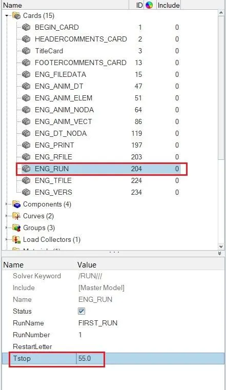
Changing the run time to 55 ms & change the number of animation time steps to 40.
Run the baseline simulation without modification of any element parameters.
Checking the energy error & mass error for baseline simulation.
Plot the rigid wall forces, internal energy, hourglass energy, contact energy & total energy of the baseline simulation.
Change into recommended element parameters from default element parameters, run it by a different file.
Check the error, plot the forces & energies for the modified simulation.
INTRODUCTION :
i) Hourglass deformation :
It is a spurious deformation that occurs from the under integrated shell elements, resulting from the excitation of zero energy generation on the node. Therefore, stresses aren't been produced, which leads to inaccurate strain and displacement results with unrealistic deformation. An element has seems deformed like a zig-zag in shape, which can see in the post-processing stage manifestly. It is also called a zero energy deformation mode.
In a under integrated element, displacement and force are exist for each node of the element.
If the summation of all these forces and displacements are provided zero stress & strain on the integration point of the element, due to that element has to calculate the stiffness for the mode deformation.
Due to no stiffness has been calculated, the deformation happens in a very weird manner.
How to control hourglass deformation :
As we know, an hourglass has occurred when we use under integrated elements.
To avoid it, have to use a fully integrated element or improved reduced integrated element.
If we use the fully integrated element(QBAT), there's no hourglass deformation will occur. But, fully integrated elements are prone to shear locking and also computational time will be increased vastly.
If we use the improved reduced integrated element(QEPH), there's has to control the hourglass deformation mode with physical stabilization, which means artificially adding the stiffness on the material. A stiffness loading depends on the natural tangent modulus. While using this parameter, will not prone to shear locking because it has only one integrated point on the surface.
If we use the reduced integrated element(Q4), there's has to control the hourglass deformation mode with perturbation method by adding the viscous to the element or adding damping on it, which means the force is applied on the node according to their element stiffness to stabilize the deformation.
ii) Element formulation :
An element formulation is a kind of defining that element behaviour, properties & it gives life to that element. This definition is varied with the type of elements used in the analysis. Typically, components are discretized by using 1d, 2d & 3d elements based on the requirement.
Have to decide the proper element formulation based on computational cost, the accuracy of the results and type of analysis as well.
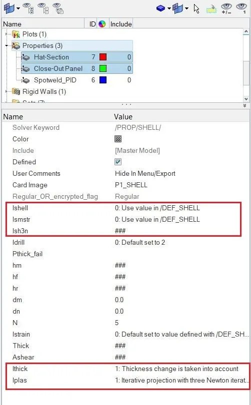
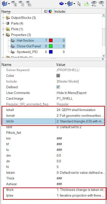
Here below-recommended element parameters for crash analysis and the same parameter have to use in the second case.
| Parameters | Comment |
|
Ishell =24 |
QEPH 4 nodes shells are the best combination of cost and accuracy. |
|
Ismstr=2 |
Full geometric nonlinearities (default)with possible small strain formulation activation in RADIOSS Engine. |
|
Ish3n=2 |
Standard 3 noded shell (C0)with modification for large rotation(default) |
| N=5 | The number of integration points set to 5 for accuracy bending. |
|
Ithick=1 |
Thickness change is taken into account for accuracy. |
|
Iplas=1 |
Iterative plasticity for good accuracy. |
Apart from the above parameters, we have a different type of element formulation for each parameter which used based on analysis types. An element formulation parameter definitions are summarized below
Element formulation for 4 noded shells :
Ishell = 1,2,3 or 4
It is named Q4 Ishell, it is an under integrated element with hourglass control by a perturbation method.
It has only one integration point on the surface.
Default shell formulation is 1.
Relatively inexpensive cost.
Ishell = 12
It is named QBAT Ishell, it is a fully integrated element with no hourglass deformation.
It has four points on the surface.
Ishell = 24
It is named QEPH Ishell, it is improved under the integrated element with physical hourglass stabilization.
It has only one integration point on the plane.
Shell strain formulation :
Small strain :
Ismstr = 1 is a small strain from time as zero.
A Strain computed based on the initial element shapes.
It takes an engineering stress-strain curve for calculation.
It is best suited for linear elastic behaviour material.
Large Strain :
Ismstr = 2 is a large strain with full geometrical nonlinearity.
It takes a true stress-strain curve for calculation.
Recommended using for crash analysis, because it covers the bending deformation.
It is best suited for nonlinear & elastoplastic behaviour material.
Element formulation for 3 noded shells :
Ish3n = 2
It is named CO, it is a standard triangle with modification for large rotation.
It has only one integration point on the surface.
There's no hourglass deformation.
Number of integration points :
N = 5
It is used to defining the number of integration points through the thickness.
A number 5 is a recommended integration point.
We can change the number of integration points from 1 to 10.
Thickness change :
Ithick = 1
It is a recommended one because it has taken into account thickness changing while solving.
A strain & stresses are calculating by using true thickness value.
Ithick = 2
It is considered the thickness is constant.
A variation thickness is computed in the post-processing stage.
Shell Plane stress plasticity flag :
Iplas = 1
Iterative projection with three-newton iterations and is more accurate
Iplas = 2
Radial return in faster.
If the Von mises stress value goes beyond the value of yield stress. Thereafter, RADIOSS will be
Update the strain through the thickness.
Compute the new thickness for the shell element.
Iplas = 1 is a recommended one.
PROCEDURE FOR OBTAINING THE OBJECTIVES :
Importing the Starter deck file :
Open the Hyperworks software, select the "RADIOSS" because we have to perform an Explicit dynamics simulation. Make sure to switch "HyperMesh" graphical user interface. Followingly, import the starter deck file through the option called "Import solver deck", select the appropriate file which is "FIRST_RUN_0000". It is an ASCII file that can read by a human.
After importing the file, a component has looked like as below.
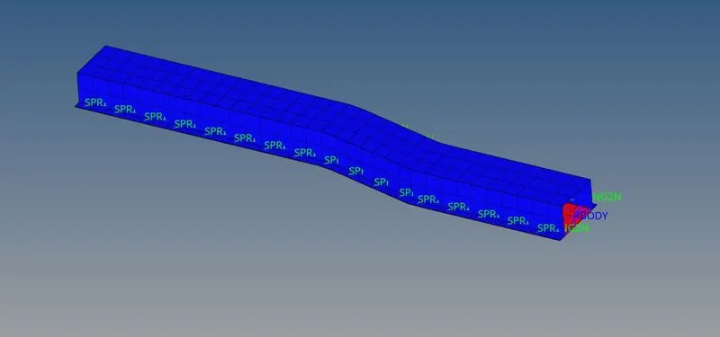
Open the "model browser", we can see the different terms such as cards, components, curves etc..,
As per our given requirement, a solver has to run the model up to 55 ms. Select the "Engine_run" parameter and give the 55 ms as a termination time as like in below.
As per our requirement, an engine must have to generate between 25 to 60 animation files. So, we take an average number which is 40, which means the solver has to create a 40 animation file within the termination time.
Rather, let say a solver will generate the animation file at which each 1.375 ms time interval.
As we know the equation for calculating the animation frequency time.
Frequency time = Termination time / Number of animation time step
= 55 / 40
= 1.375 ms
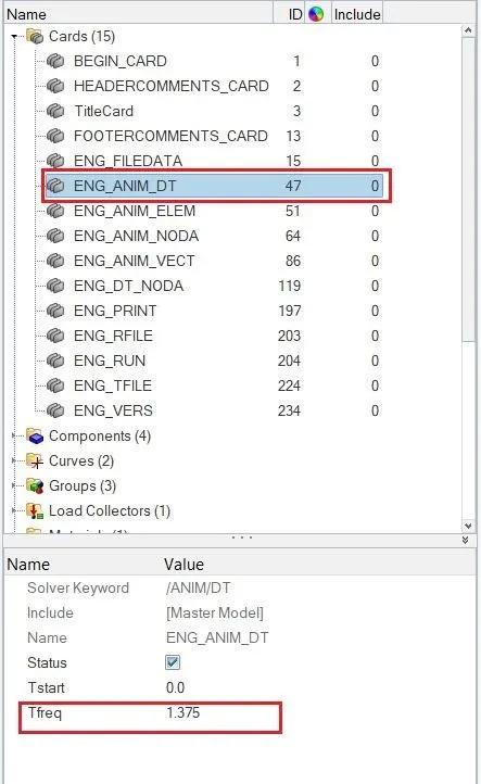
A termination time & time frequency is the same for both cases.
CASE 1
As per the first case requirement, we have to run the model by using the default element parameter like as shown below.
Followingly, select the "RADIOSS" sub-panel under wherein "Analysis" panel. Save the file where we want by separate folder and then click on to Radioss option.
The solver will compute the based according to their element parameter & other details provided.
After calculating the model, a solver is generated different files such as the Starter listing file, Engine listing file, Animation files, Time history file and then restart file.
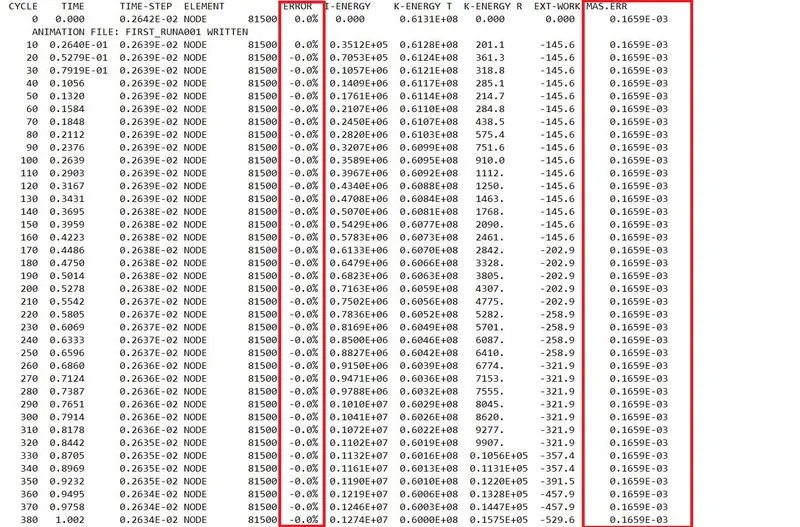
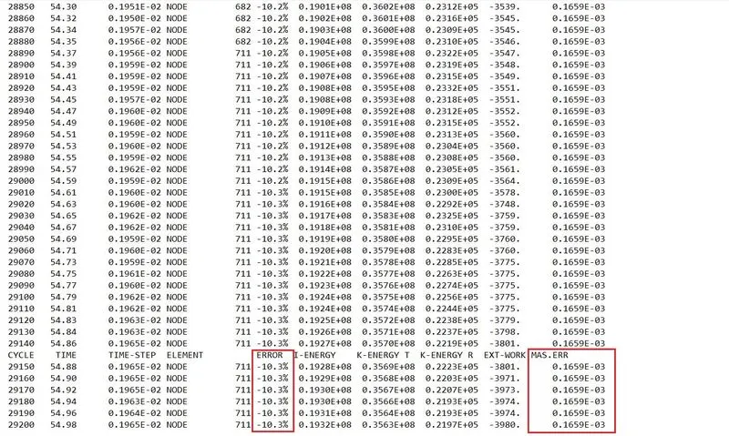
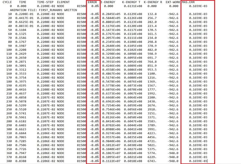
Thereafter, check the mass & energy errors which are acceptable or not. If errors can come between -15% to -5%, that can be acceptable. In this case, the error has fallen in between the acceptable range.
A mass error is always coming close to zero, it also is an acceptable one.
Now, switch to "Hyper View" mode from "HyperMesh" mode. Followingly, select the appropriated "h3d" file and click apply to open the model.
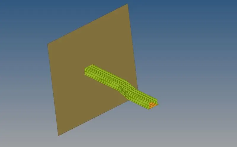
After a model has been opened, it has looked like as shown below image.
Contour plot for Von Mises stress :
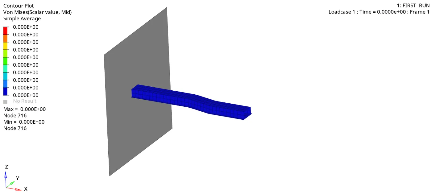
Maximum stress reaches up to 350 Mpa over the period of 55ms time.
In the bend location, a resisting strength has a little lesser than the rest of the area. So that, deformation starts from that area.
By using the simple average method, we got animation is very smooth and clearly see the variation of the stress over the surface
Then, switch to the "Hypergraph 2d" section from the "Hyper View" section.
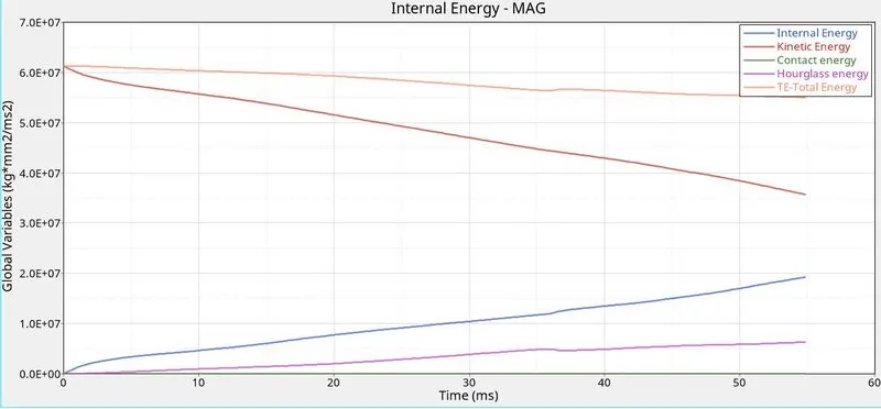
As we know the formula for Kinetic energy = 1/2 * m * V^2. As we see below, kinetic energy is decreasing from starting time to termination time. Because a displacement rate is reduced over a period of time so that kinetic velocity too decreased respectively.
As we know the formula for internal energy = Q + W. Since, there's no heat transfer in the system so only have to consider work done for calculating the internal energy. As we know, a product of force and displacement is work done. Since a displacement is continuously increased over a period of time so work done is increased, by the result, internal energy too increased respectively.
Since we kept the default Ishell element parameter which is Q4. It has only one integration point on the surface, so mostly happens spurious deformation. In order to control that, a solver has been added some energy for balancing the deformation by using the perturbation method.
The total energy is the addition of internal energy, kinetic energy and subtracts the hourglass energy which is plotted below.
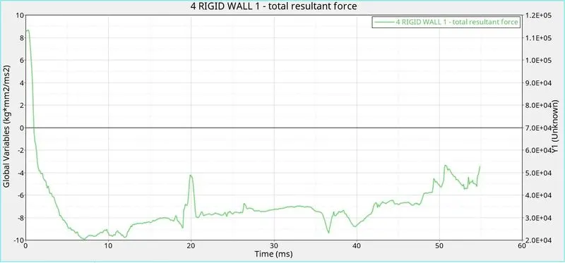
A resultant force is a resultant of x component, y component & z component. The resultant force is plotted below from starting time to termination time.
A Rigid wall means the body acts rigidly alone and ignoring the deformation.
CASE 2
As per requirement, change the element formulation into recommended element parameter like as below and run the model.
Do the same process for solving case 2 too as How did in the previous case.
The solver will compute the based according to their element parameter & other details provided.
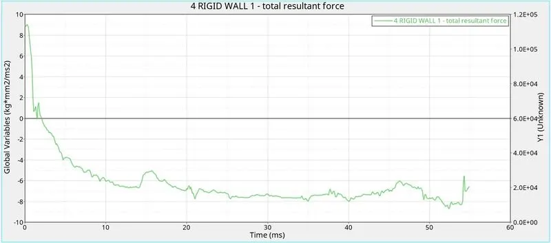
A mass error is exactly the same as case 1 and Error has been very close to 0 from beginning to ending So it is acceptable one.
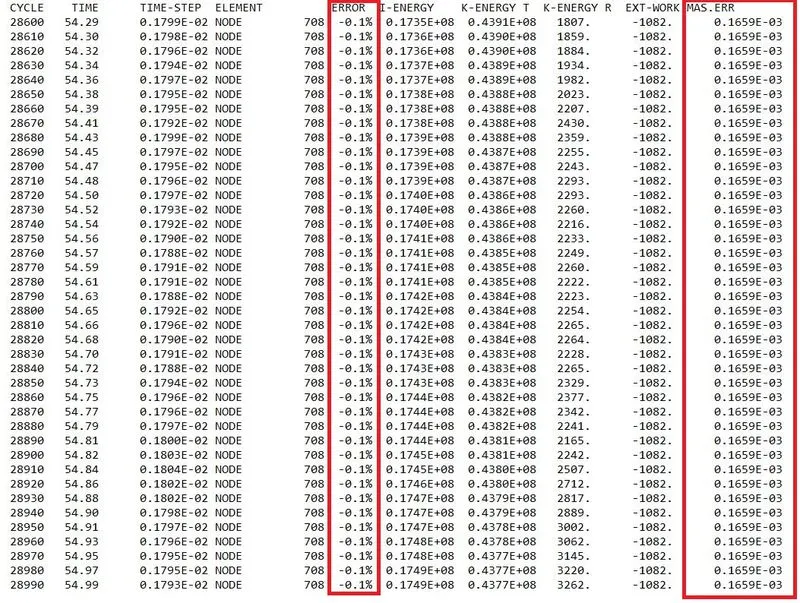
Contour plot for Von Mises stress :
As same as maximum stress reaches up to 350 Mpa over the period of 55ms time.
Initially, a bending starts at the middle part and the model is deformation heavily as compared to case 1.
By using the simple average method, we got animation is very smooth and clearly see the variation of the stress over the surface
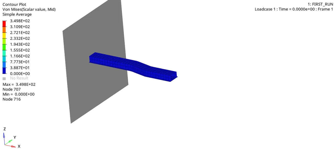
There are no changes in the Internal energy and Kinetic energy as compared to case 1. But, it seems there's no hourglass energy is generated because we used QEPH element formulation, it has been four integration point on the surface. But, it took more time than compared to the previous case.
The total energy is maintained higher as compared to the previous case due to there's no hourglass deformation has been generated.
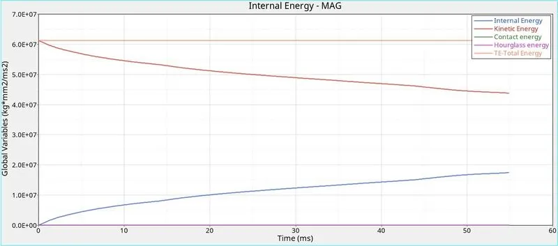
Similarly, rigid wall resultant force for case 2 as below.
CONCLUSION :
After ran both cases by using different types of element formulation has been used. There's no hourglass deformation is formed in case 2 and also maintain the results are accurate.
As we can conclude, case 2 is as effective as case 1 because of no hourglass deformation due to four number of integration point has been used.