Assignment 3-2D Element Formulation Challenge
OBJECTIVE:
To perform 2 test cases of a crashbox simulation involving different element formulations and other parameters thereby comparing results acquired from either cases.
INTRODUCTION:
Hourglass effect
Hourglass modes are non physical modes of deformation that occur in underintegrated elements and produce no stress. These effects are experienced in reduced integration linear elements that have single (hence reduced) integration point which is usually located at the elements centroid.
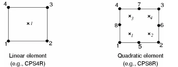
Reduced integration elements while may be computationally efficient they tend to be too flexible and less stiff because they suffer from their own numerical problem called hourglassing.
Reduced or under-integration could mean:
-Solid elements with a single integration point
-Shell or Tshell elements with a single in-plane integration point.
These reduced integration can lead to non physical zero energy nodes called hourglass nodes
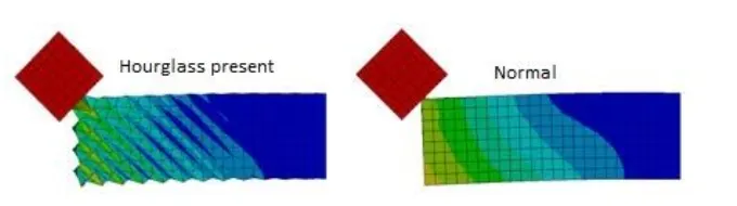
Hourglassing can be controlled by:
1. Pertubation or Viscous method
In this method, the hourglass deformation is detected with the relative motion and velocity of each nodes.
To counter hourglassing, when detected, this method applies a damping force on the node to stabilize it. The magnitude of this force depends on youngs modulus, yield strength etc.
2. Stiffness or Penalty method
This is the most efficient of the two method and most preferred.
In this case artificial stiffness is added to the element to counter the unrealistic effects caused by hourglassing.
PROCEDURE
CASE 1:
In this case, the default material and element properties are used to run the simulation with few changes to the engine (0001.rad) file.
The following changes are made:
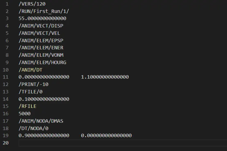
- Change the run time to 55 ms
- Change the number of animation steps during simulation to a minimum of 25 and a maximum of 60
Both the changes has to be made in the engine (0001.rad) file.
The end time can be specified under the /RUN/First_Run/1/ keyword or Tstop in the GUI under cards-ENG_RUN.
To change the freq of anim files to be written out, we modify the /ANIM/DT block.
The start time and frequency at which the anim files are written is specified in the /ANIM/DT block - Tstart and Tfreq
To write out the animation file at every 50 (25<r<60) steps for a total time cycle of 55ms, we can calculate the freq using the formula: f = T / n
f = 1.1
The changes made in the engine file are as shown below,
To run the simulation
The crashbox model is loaded onto the GUI using the started file as RADIOSS solver_deck import.
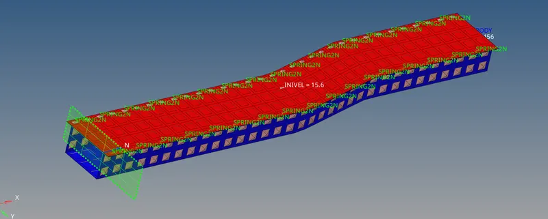
The default property cards are used for the shell elements in the model.
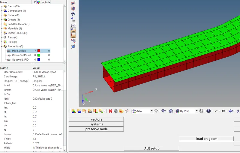
The file is run using the RADIOSS solver on a selected directory and the number of cores to be used by the solver can be specified as "-nt (no.of cores)".
The results can be viewed on Hyperview by loading the .h3d file generated in the output dir.
POST-PROCESSING
The energy and mass error can be extracted from the engine output file (0001.out).

From above, the energy error is observed to be 10.3% while mass error is 0.16E-3.
This is acceptable as it is recommended that the energy error must lie with the range of -15% to 0% for most element property cards.
The aim file can be loaded on Hyperview and the contours can be plotted.
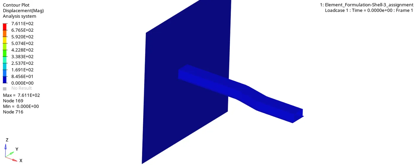
Other Global variables results can be visualized using Hypergraph 2D
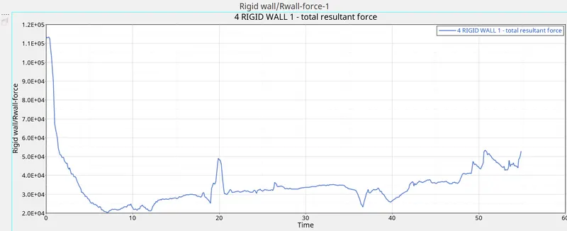
Rigid wall forces:
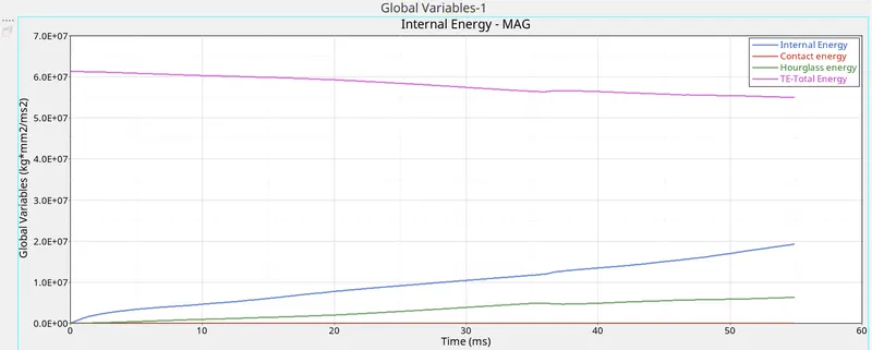
Internal energy, hourglass energy, contact energy, total energy of the simulations.
CASE 2:
The following parameters are applied for the property card.
| Parameters | Comment | |
|
Ishell =24 |
QEPH 4 nodes shells are best combination of cost and accuracy. | |
|
Ismstr=2 |
Full geometric nonlinearities (default)with possible small strain formulation activation in RADIOSS Engine. | |
|
Ish3n=2 |
Standard 3 noded shell (C0)with modification for large rotation(default) |
|
| N=5 | Number of integration points set to 5 for accuracy bending. | |
|
Ithick=1 |
Thickness change is taken into account for accuracy. |
|
|
Iplas=1 |
Iterative plasticity for good accuracy. |
After making necessary changes export the updated starter file along with the engine file to a new directory.
Rerun the simulation with the new model files.
POST-PROCESSING
The energy and mass errors are shown below
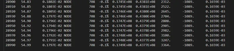
The above results are way more accurate because the energy error is observed to be -0.1%. The closer the energy error is to 0 the more accurate the results.
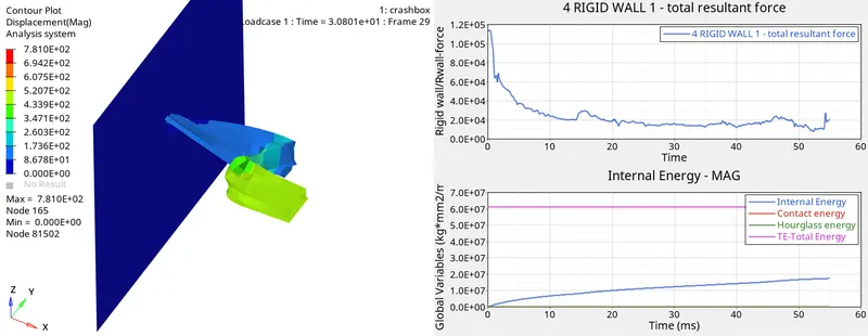
Hyperview (anim file) and Hypergraph 2D:
CONCLUSION
By comparing the data and results from both cases, we can conclude that:
- There is a significant difference in the energy error - which implies that the results extracted from case 2 is more accurate.
- There is no hourglass energy observed in case 2 - implying poor hourglass stabilization or reduced gauss integration points in case 1.
- Physical stabilization seems more likely for producing viable results.
- There is no hourglassing effect in case 2 hence due to full gauss point integration method, there is no hourglass energy to counter or stabilize it.