Assignment 3
OBJECTIVE:
- To compare the results of the base simulation with one having improved shell element properties.
- In the given crash beam file, change the run time to 55 ms.
- Change the number of animation steps during simulation to a minimum of 25 and maximum of 60.
- Run the base simulation without any modification to element properties.
- At the end of the simulation, do the energy error and mass error checks and determine whether results would be acceptable.
- If acceptable, Plot rigid wall forces, internal energy, hourglass energy, contact energy, total energy of the simulations.
- Change all the shell elements properties to recommended properties, save this as separate, rad files and run the simulation.
- Follow steps 5 and 6.
- Create a brief report comparing all the results from steps 5 and 6 for both simulations.
- Comment whether there is any change in the results and why there is any change in the result.
Recommended properties:
|
Parameters |
Comment |
|
Ishell =24 |
QEPH 4 nodes shells are best combination of cost and accuracy. |
|
Ismstr=2 |
Full geometric nonlinearities (default) with possible small strain formulation activation in RADIOSS Engine. |
|
Ish3n=2 |
Standard 3 noded shell (C0) with modification for large rotation(default) |
|
N=5 |
Number of integration points set to 5 for accuracy bending. |
|
Ithick=1 |
Thickness change is taken into account for accuracy. |
|
Iplas=1 |
Iterative plasticity for good accuracy. |
SOLUTION:
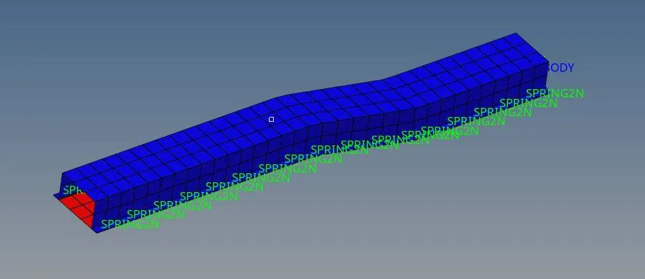
The objective of the project is to carry out crash analysis of the given model under two conditions, a base simulation with default element properties and one with modified elemental properties. This will give an understanding of how these elemental properties affect the various parameters found in the result.
Case 1: Base Simulation
The given model is run as given without any modifications. Import the model (name_0000.rad) into the Hypermesh GUI. In the ENG_RUN card, Tstop was set as 55. In ANIM_DT, Tstart was set as 25 and Tfreq as 0.916. Go to Analysis panel, select Radioss and input the file location and set option as –nt 4. To run the program, click the Radioss button. This will set help the solver to use multiple cores available in the system. Once the program runs, multiple files are generated in the result folder.
The engine output file ‘case1_0001.rad’ was opened using a text editor and the energy error and mass errors were analysed. The energy error was found to negative and continuously decreasing to a least value of -10.3% and the mass error was found to have a constant value of 0.1659E-03 throughout. These values were in the acceptable range.

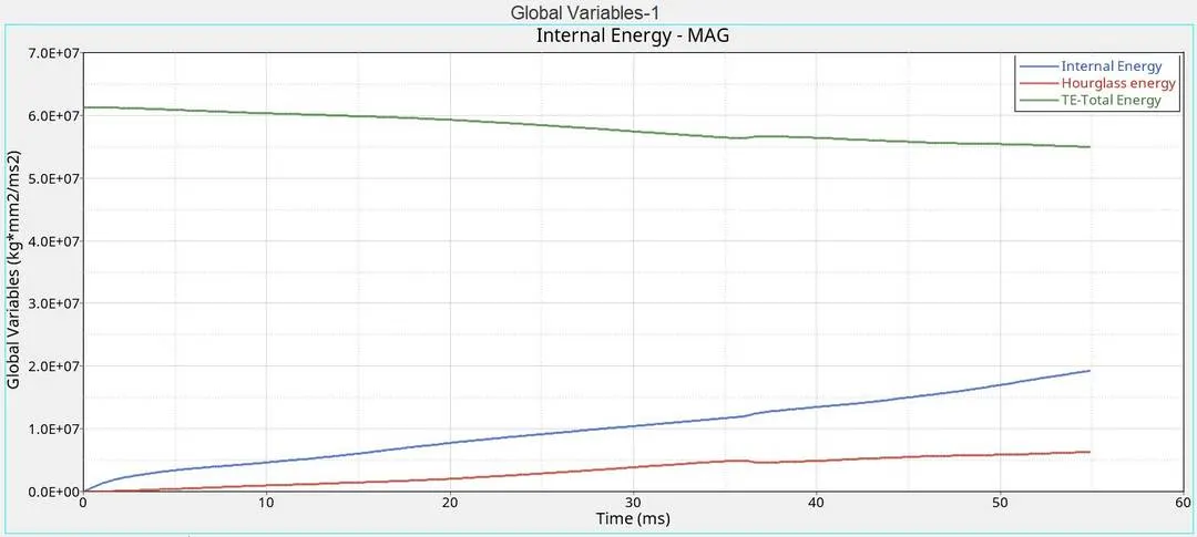
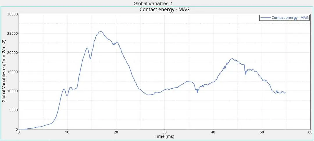
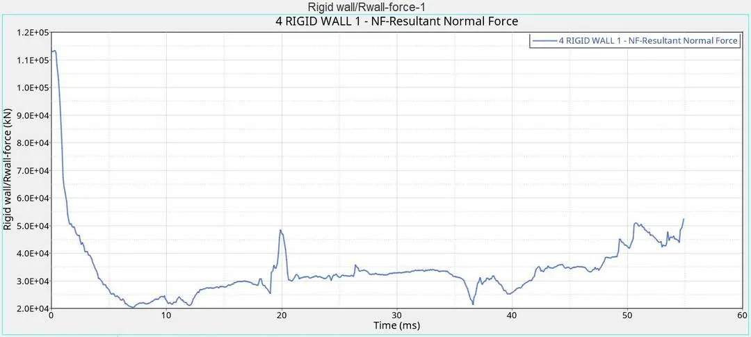
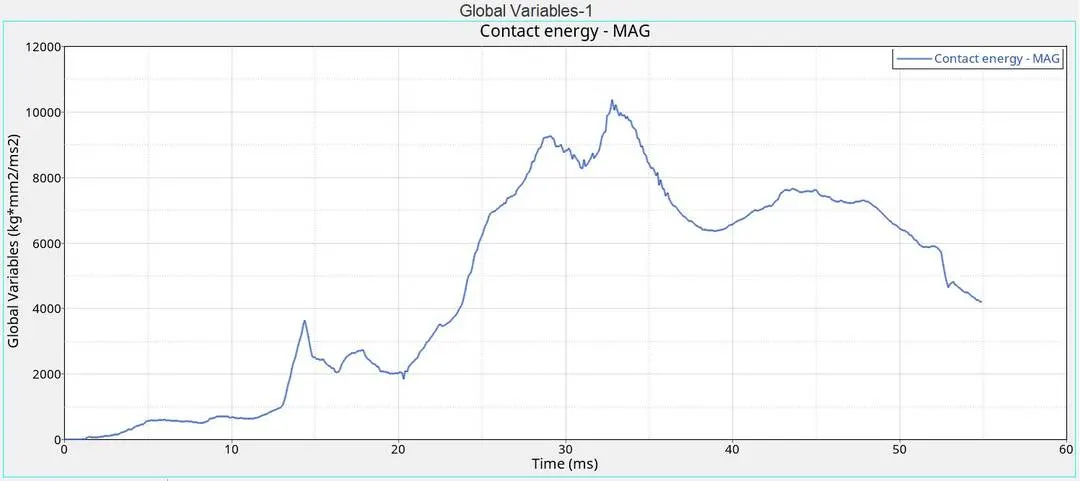
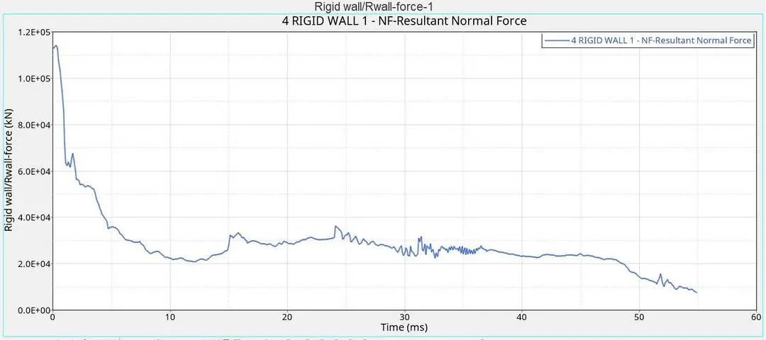
Various plots were extracted from the output file using Hypergraph. The following plots describes the rigid wall forces, internal energy, hourglass energy, contact energy, total energy of the base simulation.
Case 2: Updated simulation
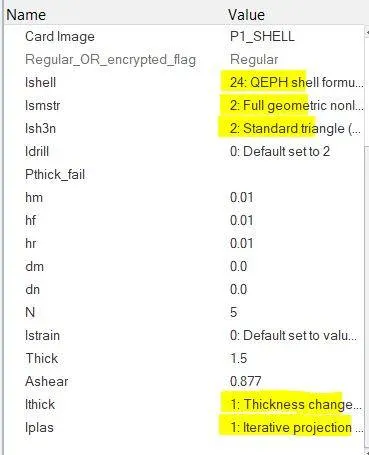
In the modified simulation, the shell element properties were changed to the recommended values and the program was run again to get the updated results. This can be done by changing the corresponding values in the property card in the model tree.
The shell element properties were set as:
|
Parameters |
Comment |
|
Ishell =24 |
QEPH 4 nodes shells are best combination of cost and accuracy. |
|
Ismstr=2 |
Full geometric nonlinearities (default) with possible small strain formulation activation in RADIOSS Engine. |
|
Ish3n=2 |
Standard 3 noded shell (C0) with modification for large rotation(default) |
|
N=5 |
Number of integration points set to 5 for accuracy bending. |
|
Ithick=1 |
Thickness change is taken into account for accuracy. |
|
Iplas=1 |
Iterative plasticity for good accuracy. |
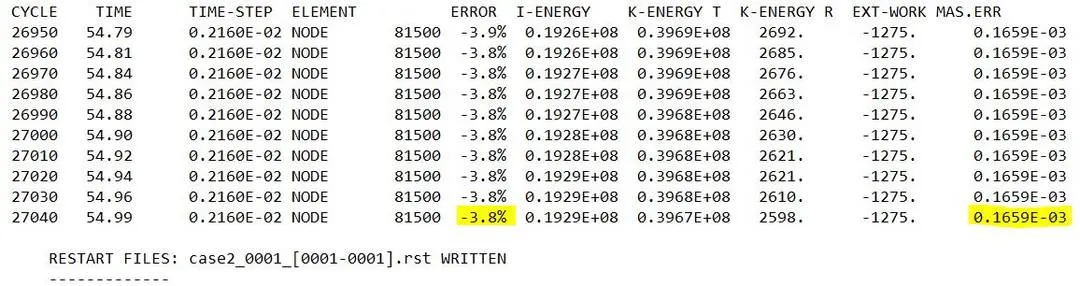
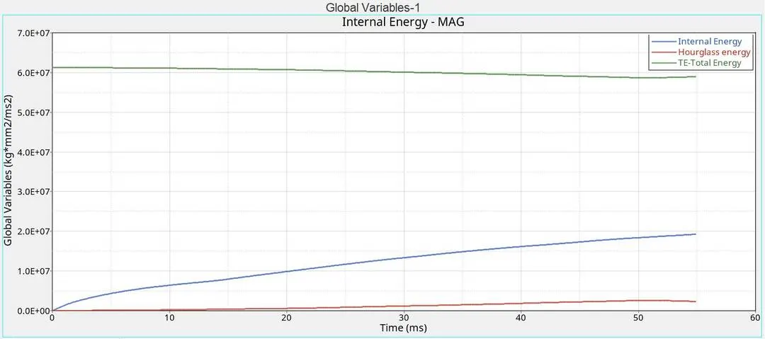
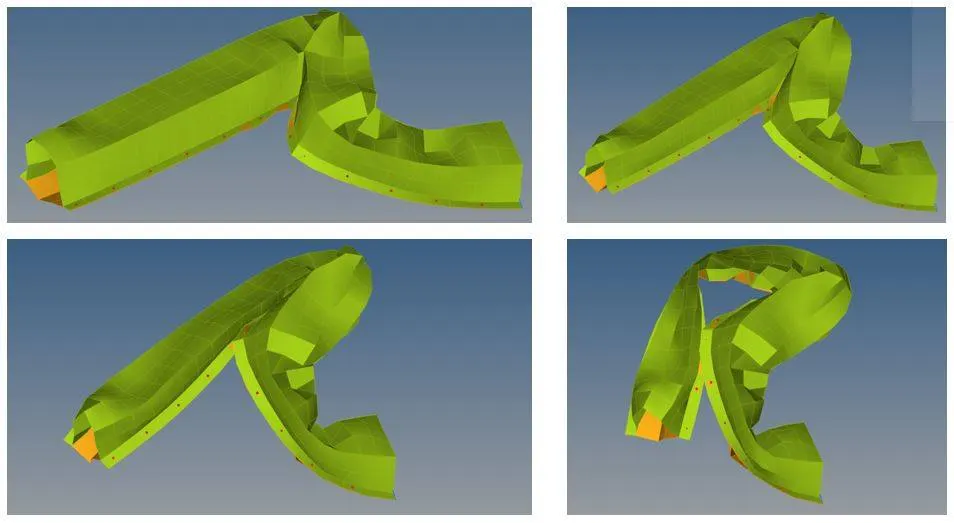
It was observed that the energy error came down drastically and attained a maximum value of -3.8%, which signifies the model is good. No change was observed in the mass error. The different plots obtained for the simulation are given below:
HOURGLASS ENERGY AND ITS CONTROL:
Hourglass energy or modes are nonphysical modes of deformation that produce no stress. Such errors are commonly seen in under integrated elements, which means elements (solid or shell) with single integration points. This means that during a simulation deformations are found to occur in the elements but no energy is being recorded corresponding to these deformations. This arises errors in the solution leading to inaccurate simulations. This can be avoided by using elements having more number of integration points or that using better integration schemes. Two commonly used methods to tackle this issue are:
Perturbation method – Q4 Elements
Physical Stabilization – QEPH Elements
Perturbation method is used when Q4 element (Ishell = 1 to 4) formulation is used. This method is called viscous method and artificial forces are introduced at the nodes to stabilize the hourglass errors. Whenever an hourglass deformation is detected by the solver, an artificial energy called as hourglass energy is applied on the nodes to achieve better stabilization. This force is defined according to the element stiffness (found using material properties including youngs modulus, yield stress, plastic tangent etc). This method may exhibit bad performance in case of large rotation and distortions and in case of elastic load – unloading cycles. It also inhibits additional hourglass deformations. This method is recommended in problems involving high velocity and high strain rates (like explosion problems).
In QEPH element formulation (Ishell = 24), also called stiffness method, the hourglass errors are stabilized at the material level. This gives more accurate results in case of loading and unloading and it is able to reduce total accumulated hourglassing deformation. This method is preferred for lower strain rate problems including crash simulations.
OBSERVATIONS & CONCLUSIONS:
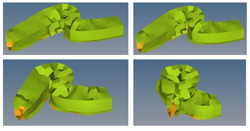
- It was observed that the energy error fell drastically when the element properties were updated. The maximum error value in the base simulation was found as -10.3%, while the same for the updated simulation was -3.8%.
- A similar trend was also observed in the hourglass energy plots. For the base simulation the hourglass energy attained significant value over the entire simulation. The same was found to be much less for the updated simulation.
- The magnitude of the contact energy was also found to have almost halved after the updating the elemental properties.
- The reason for these changes lies in the updated elemental properties. In case2, the QEPH elements were used for the shell formulation which gives more accurate results because of the minimised hourglass energy errors. By setting Ishell as 24, we are using QEPH elements which has an improved reduced integration scheme that reduces the cost of computation while providing higher accuracy. This uses the stiffness method to reduce the hourglassing effect. This reduces the energy errors significantly and also shows gives lower hourglass energy in the plot.
- It was observed that the elemental deformations in the updated simulation was more realistic compared to that of the base simulation.