Assignment 2-RADIOSS Engine File Editing & 3D Meshing Challenge
AIM :
To Calculating the values & Editing the values on the engine file and performing the volumetric meshing on the given models.
OBJECTIVES :
Calculate speed of the sound for steel rail & Calculate the time for sound to travel over length of the rail.
Edit the engine file fro termination time & animation time step.
Performing shell meshing on the Housing surface and fixing the quality issues.
Performing Volumetic meshing with tetrahedral elements for housing component and fixing the tet collapse errors.
Performing Volumetric meshing with Hexahedral elements for arm bracket.
PROCEDURE FOR OBTAINING THE OBJECTIVES :
I) Check the material properties of the rail component and calculate the speed of sound for steel rail :
In order to calculate the speed of sound for steel rail, we have to use this formula has been written below.
`c=sqrt(E/rho)`
where,
c is speed of sound.
E is Young's modulus.
Rho is Density.
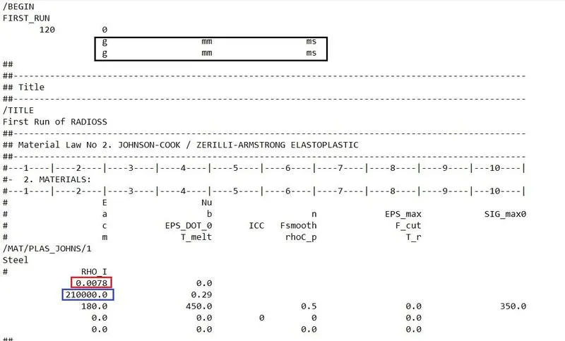
As we can see from above image, a density & Young's modulus values are given in the starter file. A density is 0.0078 g/mm^3 & Young's modulus is 210000 N/mm^2.
`c = sqrt(200000/0.0078)`
c = 5188.745 m/s
II) The length of the rail is about 1000 mm, calculate the time takes for a shock wave to travel from one end of the rail to the other
By using speed formula, we can able to calculate the time difference for shock wave to travel between from one end of the rail to other end of the rail.
`Speed, c = (Distance)/(Time)`
`5188.745=1000/(Time)`
`Time = 1000/5188.745`
Time Difference = 0.1927 sec.
III) Time for sound to travel over length of rail
Time for sound to travel in length of the rail is same as time takes for shock wave to travel from one end of the rail to other.
Therefore, a time for sound to travel length of rail is 0.1927 sec.
IV) Set the frequency of animation output to a time that will give 20 animation steps
Time frequency for animation output, will be give 20 steps.
Time frequency for output = Total time / 20
= 0.1927 / 20
= 0.0096325 sec
V) Editing the engine file
We have to edit where at place of termination time & animation time step in the starter file which is saved as "FIRST_RUN_0000.RAD".
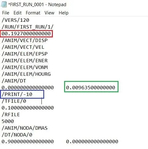
First, changed the termination time into 0.001927 which has annotated in red color box.
Secondly, changed the animation step time into 0.0096350 where the place of "animation time difference" which has annotated in green color box.
Make sure edit carefully while changing the number, a decimal place shouldn't be changing.
And also requested for edit the printing difference into 10. But, the value is already setted as same in the engine file.
VI) Peforming Volumetric meshing :
1) CAD models :
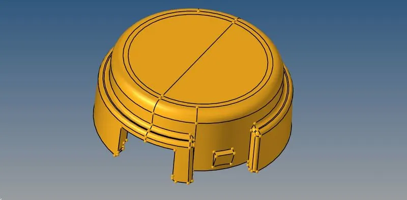
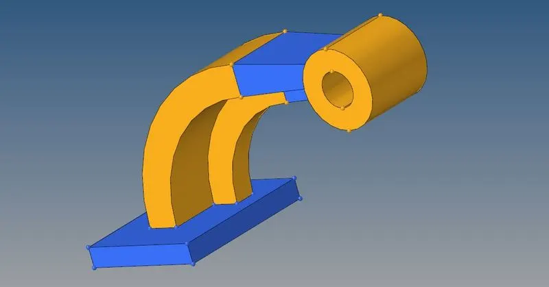
Open the Hypermesh software, followingly select the "Import model" option & choose the file type is "Step". Select the appropriate file which we want to perform & click to import. Once a model is imported, it have been visible in the graphical window like as shown in below images.
i) Housing :
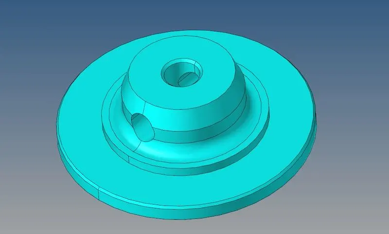
ii) Arm Bracket :
2) Geometry Cleanuping :
First of all, change into "By topo" mode instead of "Auto" mode, now we can able to see the topological edges from the component such as "Free edge", "Sharded edge", "T-Junction edge" & "Supressed edge".
If given component has being an solid, then delete the solids and keep surface only.
Housing :
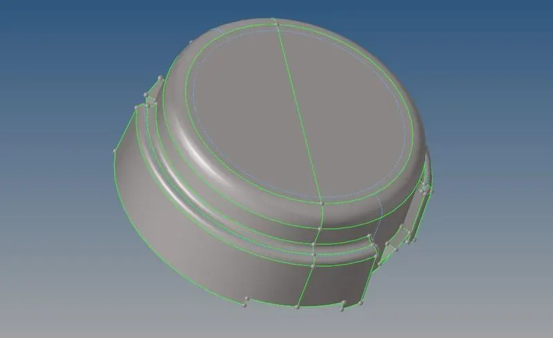
For Housing, we just need to supressing excess few sharded edges which are affecting due to minimum element length criteria while doing shell meshing on it.
After supressing, a housing part has looks as shown in below.
Arm Bracket :
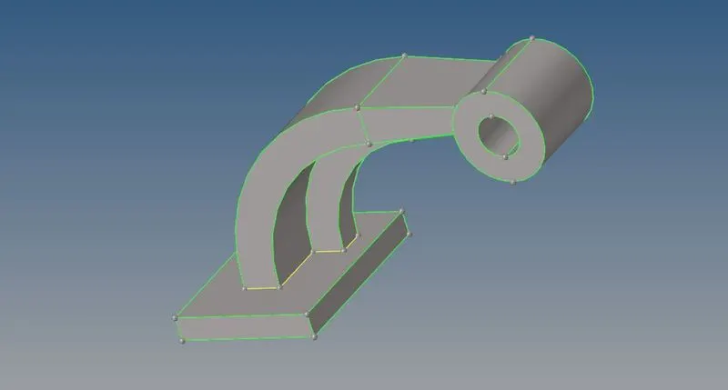
In this model, there's no need of geometry cleanup. Few surfaces are not properly organized, we just need to organize them in that respective collector.
3) Volumetric Meshing :
A Housing component have more curved surfaces, a hexa meshing is not possible for this component. So, we should preferred Tetra meshing for housing component.
A Arm bracket haven't much curved surface as compared to housing component. We can preferred Hexa meshing for this component.
Tetrahedral Meshing :
For tetrahedral meshing, we have a three methods which are available in Hypermesh for generating the tetra mesh.
Which are,
i) Perform shell meshing with tria elements and generate the tetrahedral elements.
ii) By using Volume tetra option
iii) By using Quick tetra mesh.
i) Method 1:
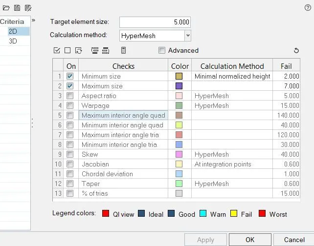
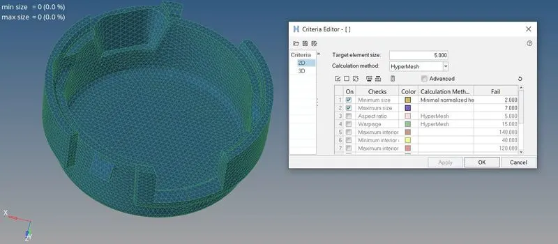
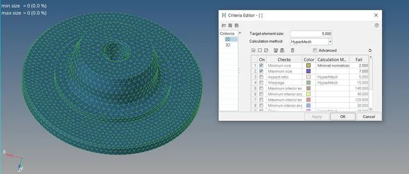
First of all, setting up the proper element quality crietria like as shown in below. We only consider minimum & maximum element length criterias while performing an shell meshing with tria elements.
Open the "automesh" option, keep element size is 5 mm & element type is tria. Performing meshing in surface by surface.
A generated mesh is looks good and it's passess quality criteria.
Generate tetrahedral elements using shell elements
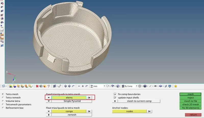
In order to generate the tetra elements, a shell elements should be closed volume.
Select the "Tetra mesh" option, switch to elements instead of components and followingly select the outer component shell elements and then click to mesh.
Hypermesh can generate the tetrahedral elements with reference of shell elements and according to their growth rate.
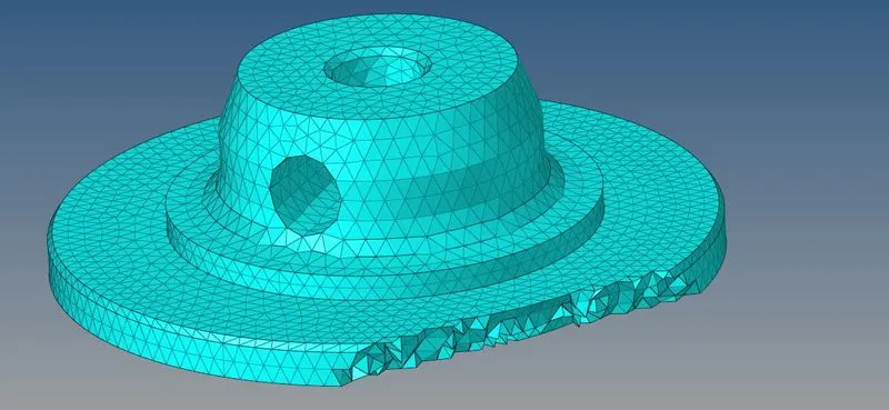
Now, as we can see from below, a tetrahedral elements are generated.
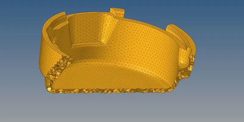
Similarly generated the volumetric elements for inner component as well.
Fixing the Tet collapse error :
For tetrahedral meshing, we have to consider only "Tet collapse" criteria. Now, a lot of volume elements are failing due to tet collapse criteria, it has shown in the status bar.
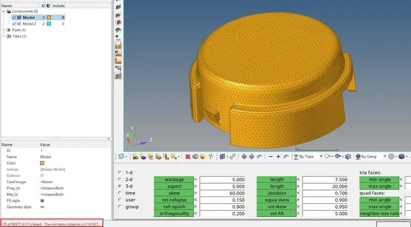
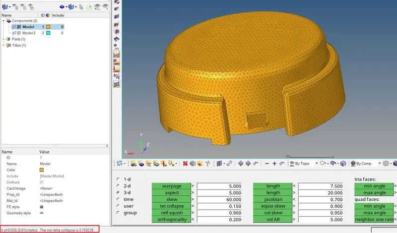
In order to get rid of this error, we have to remeshing on it until failed elements are to be passing.
After done the remeshing on it, all volume elements are passed for "tet collapse" error as shown in the status bar.
ii) Volume Tetra option :
In order to performing an tetra meshing by using volume tetra option. Keep a component as a solid or surface, a 2d element type is tria & 3d element type is tetras.
Enable the "Use curvature" & "Use proximity" if need to capturing the fine elements around the holes.
Keep Element size is 4 mm & click the mesh option to generate the tetrahedral elements.
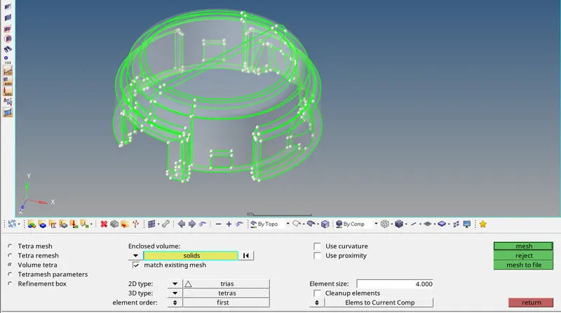
After generted the tetrahedral elements by using "Volume tetra", a created elements are organized into new collector.
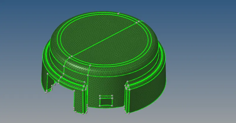
Fix the tet collapse as same as like previous case. A more number of elements are failing as compared to "Tetra mesh" method.
iii) Quick Tetra mesh option :
Enable the "Utility" option from the "view" pull down menu bar, after that we can able to see the "Utility" option at which left tab.
Followingly select the "Geometry/mesh" option by utility section itself and then choose the "Quick tetra mesh" option.
In the quick tetra mesh section, we can select the visible component as a "volume complist", change into "only trias" for mesh type like as shown in below and click the mesh option.
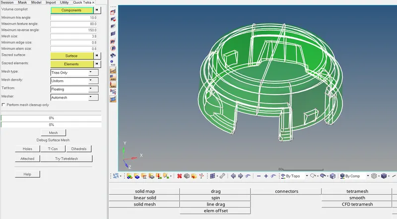
A "Quick tetra mesh" algorithm is performed geometry cleanup, surface meshing & volumetric meshing by itself.
After done all process, a tetra meshed model has looks like as shown in below.
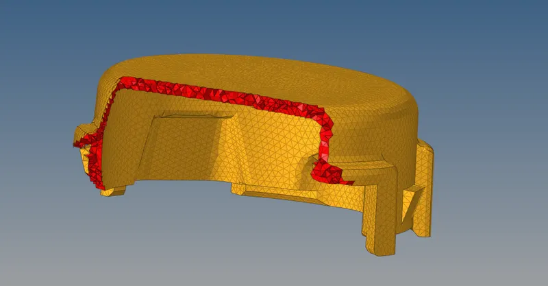
Fix the tet collapse error by remeshing on it as same as like previous case. Comparatively, it have less tet collapse error as compared to previous case.
Hexahedral Meshing for Arm bracket :
For generating hexahedral meshing, we have an different option which are available in Hypermesh. We can use different option to create a hexa mesh according to shape of the component.
By using solid map option for base part :
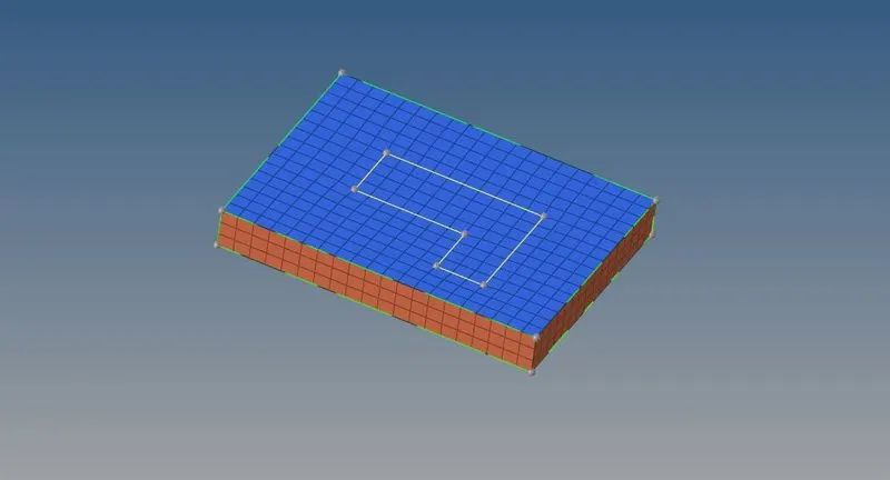
Perform shell meshing with quad elements only & 10 mm size on the top surface like as shown in below.
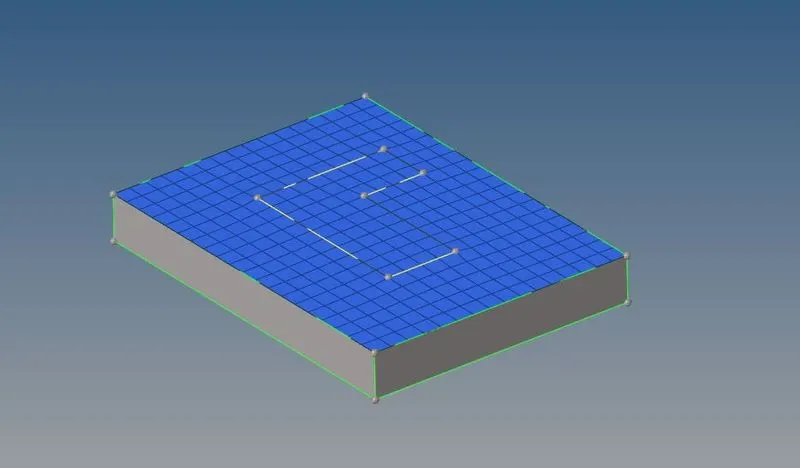
Select the "Solid Map" option and select "general", to select the shell elements as a "elements to drag", to select the bottom surface as a "destination geometry" & select the side faces as a "along geometry" and along size is 10 mm. Then, click to mesh.

An brick or hexa elements were generated for base part as shown in below.
By using element offset option for Arm curve :
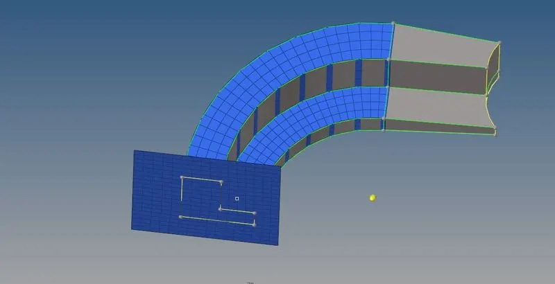
First of all, create a center node by using "three nodes" distance option.
Select the 2d elements, switch to "x axis" because we have to spin it about an x axis. An angle is 90 degree, a "on spin" is 25 which means 25 interval along the curved line and then click to spin negative.

After generate the hexa mesh for arm curve, it has looks like as shown in below.
By using Linear solid option for arm straight
Generate the shell meshing with quads only on front face & create the edge face on the hexa elements as shown in below.
Make sure keep number of elements to be same from start to end.
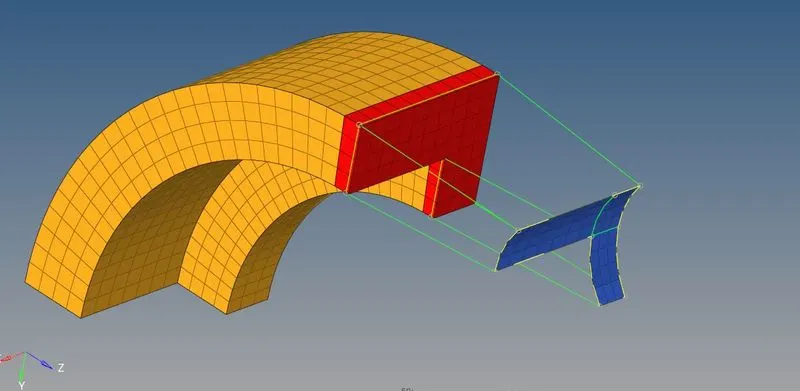
Select the cross sectional edge face as a "from elements" along with select the alignment node in proper manner & similarly select the shell elements as a "to elements" with select the alignment in proper manner.
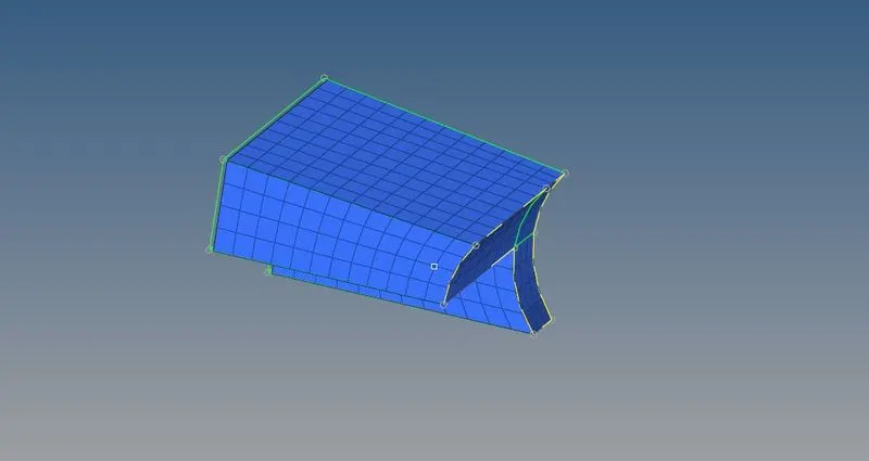
A density is 12 which means 12 intervals between start to end. Then click to proceed.

After generate the solid elements for arm straight part, it has looks like as shown in below.
By using solid map option for boss :
Performing shell meshing with quad elements on the top face as like in below.
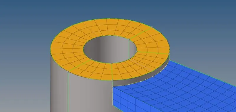
Select the elements for drag, select the node for 3d element faces as shown in below image & select bottom face as a destination geometry. Click to mesh.

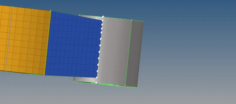
Now, a hexa elements is generated with proper connectivity between the elements in the boss part as shown in below.
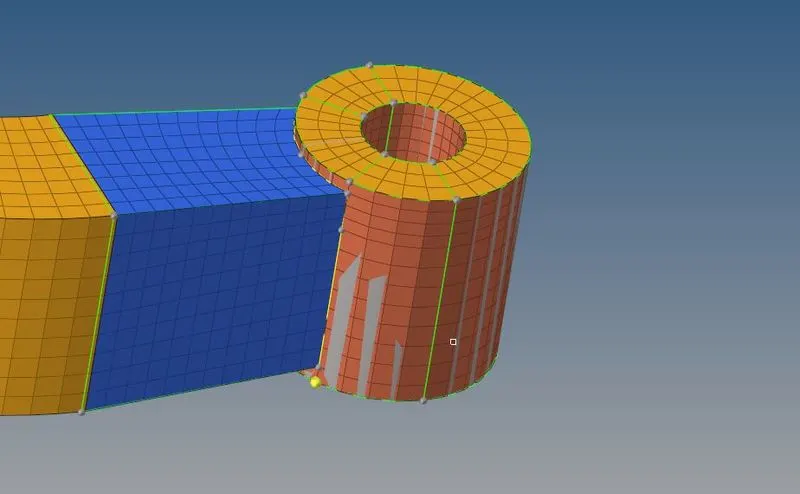
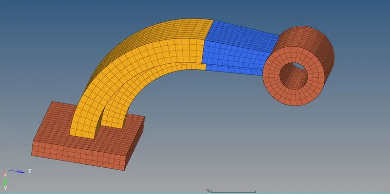
Final meshed arm bracket :
CONCLUSION :
Calculated the values such as speed of sound for steel rail & time for sound to travel over length of the rail and edited the termination time & animation step time in the engine file
Performed volumetric meshing with tetrahedral elements in the housing component.
Performed volumetric meshing with hexahedral elements in the arm bracket.