Assignment 2-RADIOSS Engine File Editing & 3D Meshing Challenge
OBJECTIVE:
To modify the parameters in a Starter and engine file.
To generated volume meshing on two components - Housing, Arm bracket
PROCEDURE:
1. Calculate the speed of sound in rail:
The speed of sound over a material can be calculated by,
`c = sqrt(E/rho)`
where, E - Young's modulus or modulus of elasticity (N/sq.mm or MPa)
rho - Density (Kg/sq. mm)
The material properties can be found in the FIRST_RUN_0000.rad file which can be opened using any text editor (shown below)
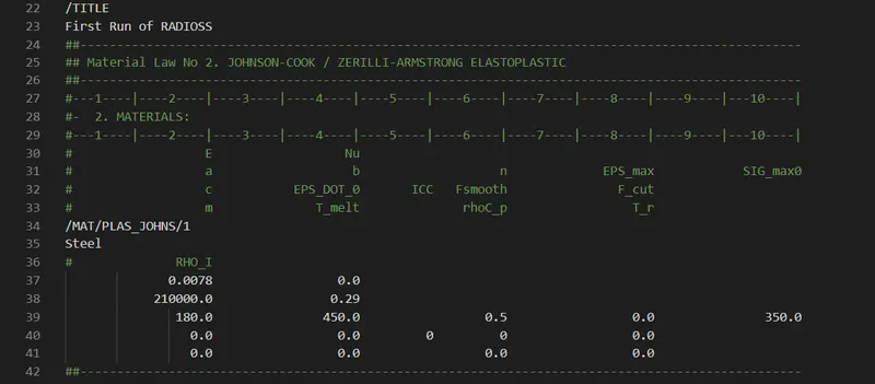
Hence, E = 210000 and Density = 0.0078
`C = sqrt (210000 / 0.0078)`
`c = 5188.74 m/(s)`
2. Calculate time takes for a shock wave to travel from one end of the rail to the other:
wkt Length of rail, l = 1000mm
To calculate the time step required to reach the other end of the rail
`triangleT = l/c`
`triangleT = 1000/5188.74`
Hence, the time taken is about 0.192 ms
3. Time for sound to travel the length of rail in air
The time taken for sound to travel over the rail would be the same as the time required for a shock wave to propagate over the length of the same rail.
Hence, the time taken would be 0.192ms
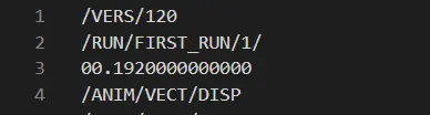
4. Control Termination
To set the end time as 0.192ms, the engine file FIRST_RUN_0001.rad can be edited as shown below
5. Change frequency
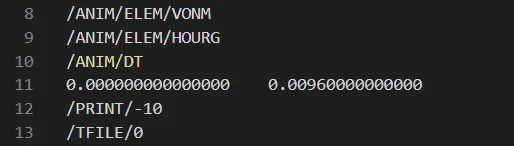
The start time and frequency at which the anim files are written is specified in the /ANIM/DT block.
To write out the animation file at every 20 steps for a total time cycle of 0.192ms,
`f = T / n`
`f = 0.192 / 20 = 0.0096`
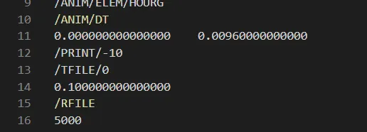
6. Change /print -10
This represents the printout cycle frequency for listing
3D MESHING
MODEL 1: Housing
The model is imported and checked for geometrical errors
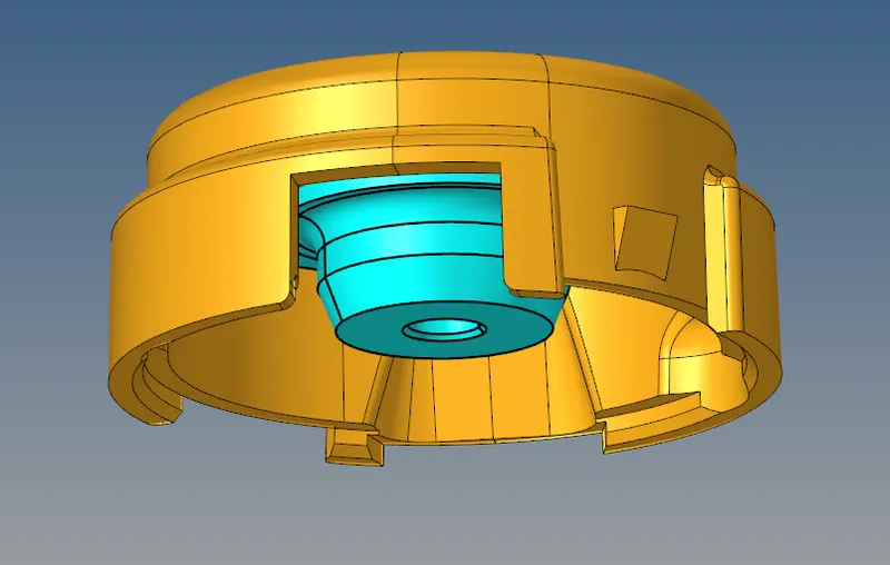
Shell meshing
- To generate shell elements:
- 2D - automesh - elem length = 5 - elem type = trias - 1st order - mesh
- The mesh is check for min and max length failure of below 2mm and above 7mm respectively.
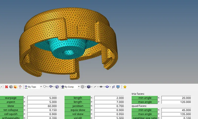
- Elements that fail quality can be cleared using cleanup tools in the quality tab or by remeshing the component.
- If elemets form at corners and fail for min length, these can be cleared by pasting nodes using the replace option (f3)
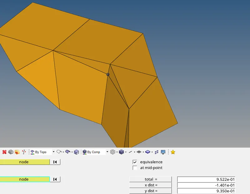
Volume mesh
- Volume mesh are generated by mapping opposite sides of the FE model and the corresponding elements.
- To generate a 3D mesh:
- 3D - tetramesh - specif parameters - mesh
- The two different initial ways to generate 3D elemens are using tetramesh and volume tetra.
- The tetramesh feature required a pre-existing 2D element for mapping. Alternatively can be generated diretly using the Utilities tab
- The volume tetra feature by default creates a shell mesh then generates the volume mesh
- In tetramesh the elemns of the 2D mesh elems are selected and split quads into trias is selected rather than generating pyramid elements.
- NOTE: Before generating the 3D elems of a certain comp make sure that comp is set as current
- Finally the component and the tetras can be visualized by masking few elements at the outer side.
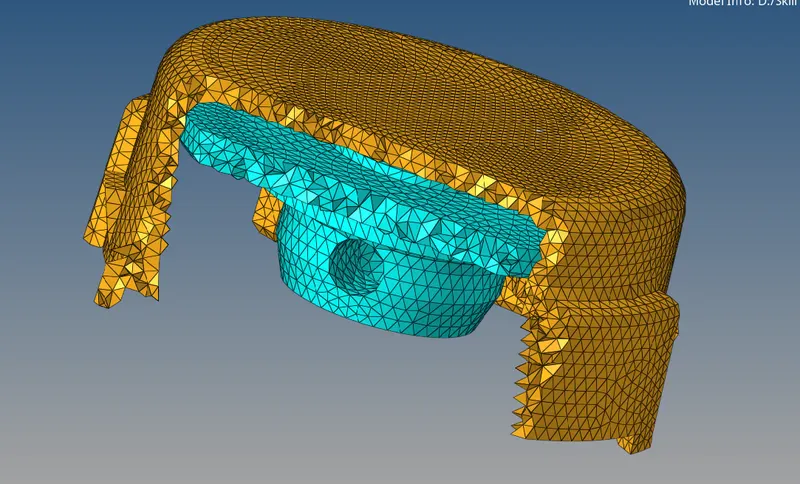
Tet-collapse
- Similarly as done for shell mesh, the 3D elems are also check for quality.
- The most commonly used parameter for tetra quality check is tet-collapse.
- It checks how far the elem deviates from being perfectly ideal or tetra. This means the every node must be equidistant from each other to be ideal. However a tolerance of 0.15 is set. The elem nodes shouldnt go below this level.
- To rectify this either the failed elems can be masked and remeshed using tetra remesh or maually rectified by setting the distance between each element.
MODEL 2: ARM BRACKET
Using Line Drag (base feature)
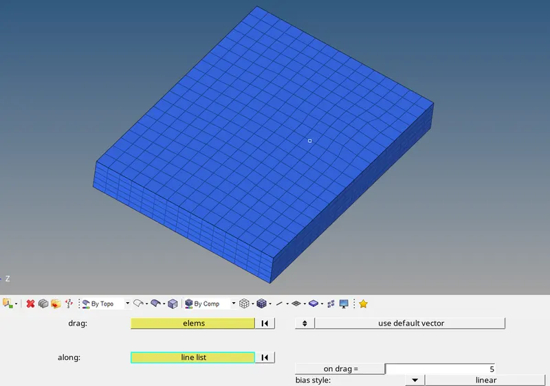
The base is meshed using the shell meshing option with a target length of 10mm. Only the top face of the base feature was meshed.
Using the line drag option, first the elems are selected and the direction is specified with the line along the thickness of the component. The on drag is set to 5 so 5 layers of hexa(brick) elems are generated.
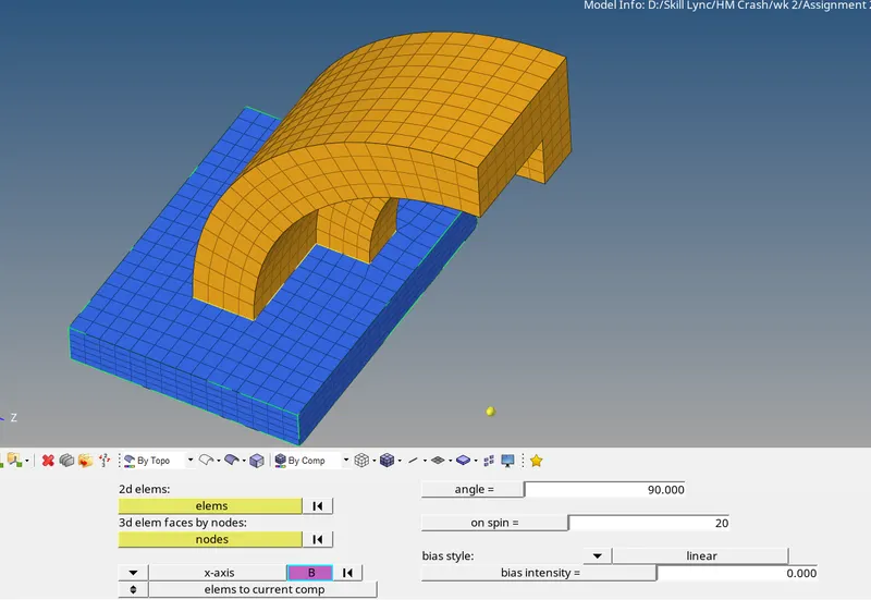
The next feature is meshed with 3d elems by spinning the elems at the base feature.
Prior to this, an arc centre is created using the nodes command
Using spin command, the elems are reflected to an angle of 90deg with 25 layers along the component
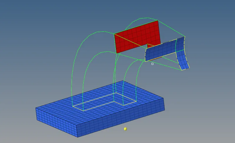
The next component can be meshed with solid elems by linear solid command.
Prior to this the 2d elements of the previous comp face is extracted using tools-> faces. Then the comp face is meshed using automesh with the same no of elems corresponding to the other face.
Then using linear solid we can create solids between the two shell elems. A density of 10 layers is set (as shown below)
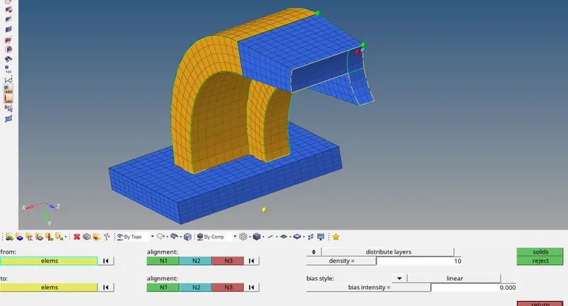
At the end, every quads are deleted using the config method in the delete elems tab
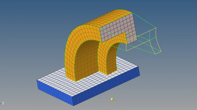
For the boss component, similar to the base feature a shell mesh can be generated at the top face and dragged along the geom using the line drag command however connectivity issues with the adjacent component can occur
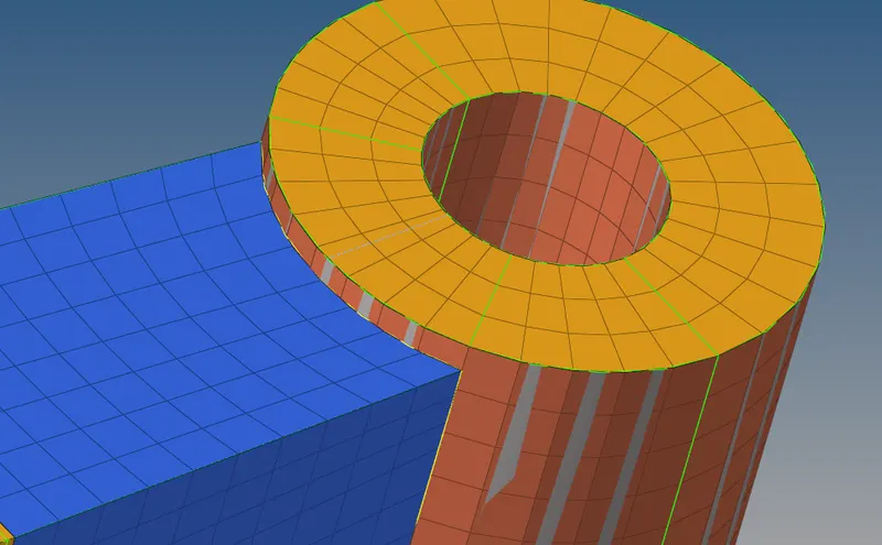
Hence for such case, the node path can be used to specify the direction and to maintain connectivity
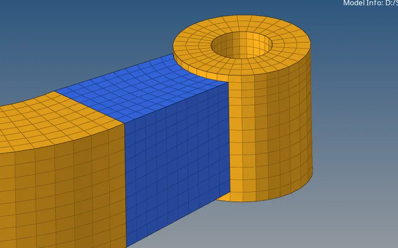
Again after deleting any quads the final mesh is achieved
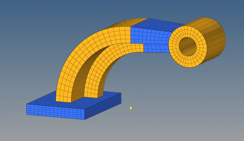
Hence the meshed arm bracket model is shown below
CONCLUSION:
Hence the following changes have been made to the starter file and engine file using a text editor.
The given components - housing and arm bracket were meshed using tetra and hexa elements