Assignment 2-RADIOSS Engine File Editing & 3D Meshing Challenge
1. Check the material properties of the rail component and calculate the speed of sound in steel rail.
The material used is steel and the properties of the material are given below.
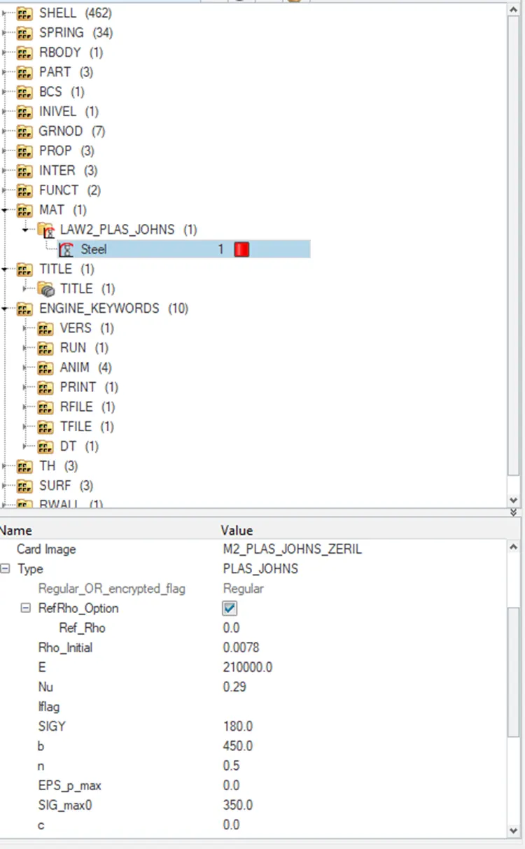
Since we know the youngs modulus and the density, the speed of sound in steel is calculated as
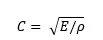
So, the speed of sound in rail is 5188.745m/s.
2. The length of the rail is about 1000 mm.calculate the time takes for a shock wave to travel from one end of the rail to the other.
The length of the rail is given as 1000mm.
Time taken dt = l/c = 0.192ms
3.Time for sound to travel length of rail = 0.192ms
4.Edit the engine file so that the stress wave can be monitored, moving from one end of the rail to the other during impact -this will require a termination time equal to the time it takes for the sound to travel the length of the rail.
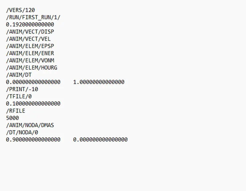
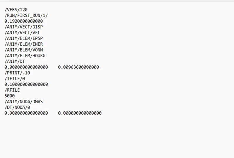
5.Set the frequency of animation output to a time that will give 20 animation steps
Frequency = time/no.of revolution = 0.192/20 = 0.009636
7.3d meshing tetra mesh and hex mesh
- Repeat class examples and, maintain the quality.
- Target tet size=5mm,hex size=10mm,tet collapse=0.15.
Objective : to 3D mesh the arm bracket.
Procedure : Step 1: Select the base and perform 2d meshing on the top surface as shown in figure 1
Target elemet size : 10mm(hex element)
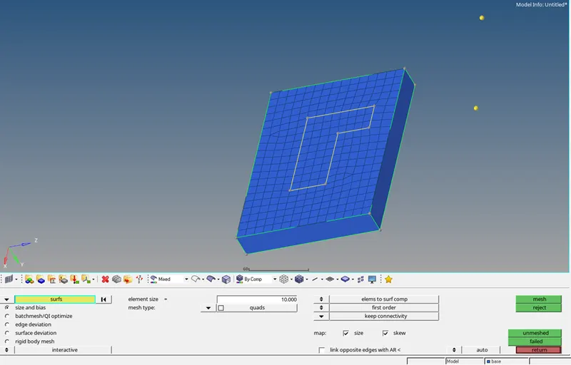
Figure1: 2d mesh of the base top surface.
Step 2: Offset the 2d elements using the option 3d – element offset to offset the elements to the part as shown in figure 2
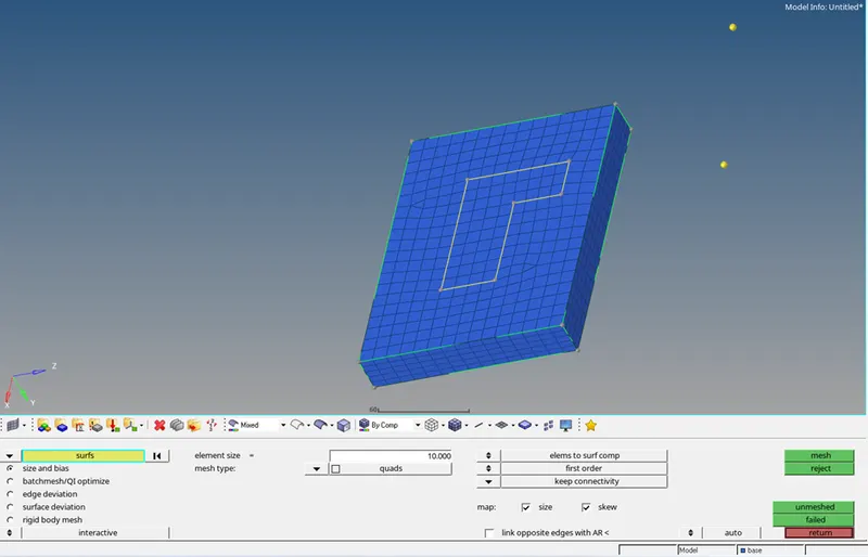
Figure2: 2d mesh of the base
Step 3: Select the centre point for the curve to spin the elements to the arm curve from the base part using the distance option.
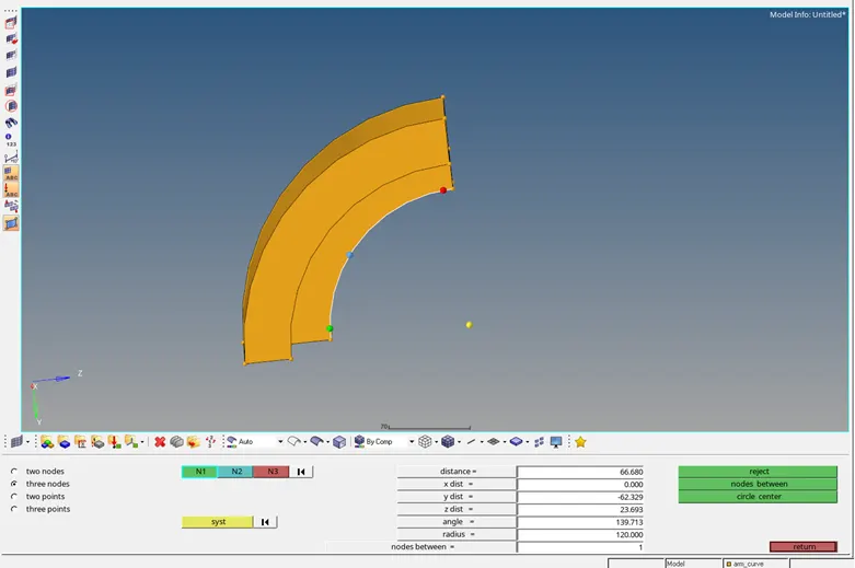
Figure3: Centre point for the arm_curve.
Step4: Select the elements as shown in the figure and use the spin option in 3d tab to spin the elements.
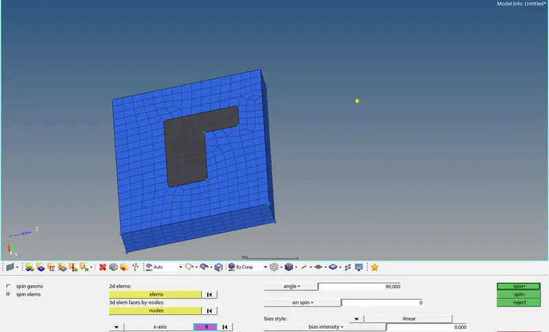
Figure4: Elements used for spin.
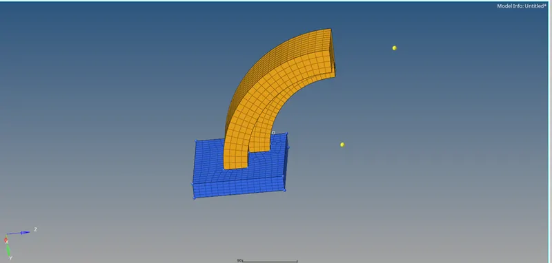
Figure5: Meshed base and arm_curve
Step5: Select the face using tool – face as shown in figure. Use 2d meshing and mesh the front part of the arm _straight as shown in figure. Make sure that the number of elements is same in the face of the arm__curve and the arm _straight. Liner solid option from 3d tools is then used to create the 2d mesh for the arm _straight.
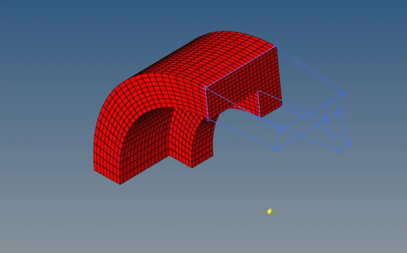
Figure6: Face selection of the arm_curve
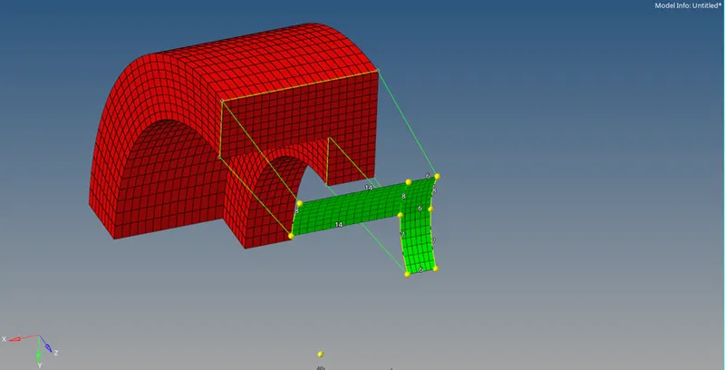
Figure7: 2d mesh of the arm_straight (front face)
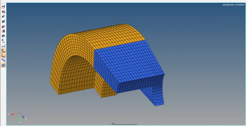
Figure8: 2d mesh of arm_curve and arm_straight
Step 6: Create a 2d mesh on the top surface of the boss. Further, offset the elements using the solid mesh option from 3d tools.
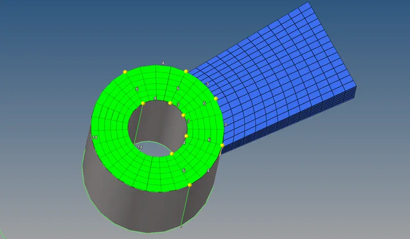
Figure9: 2d mesh of the boss top surface
Step7: Organise the created mesh according to the part.
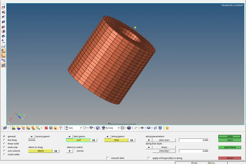
Figure10: 2d Meshed boss part
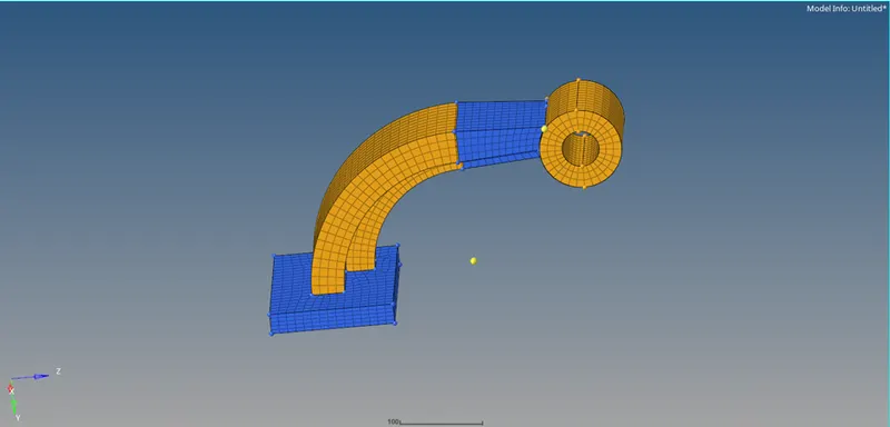
Figure11: 2d meshed arm bracket
8) 2D meshing
Objective: To mesh the hub housing using 3D tetramesh.
Step 1: Mesh the cover using 3d volume mesh
3D - tetramesh - volume tetra.
The following mesh quality is used and tet collapse is checked for 0.15

Fig1: Mesh quality setting
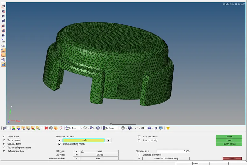

Fig2: 3D volume tetramesh
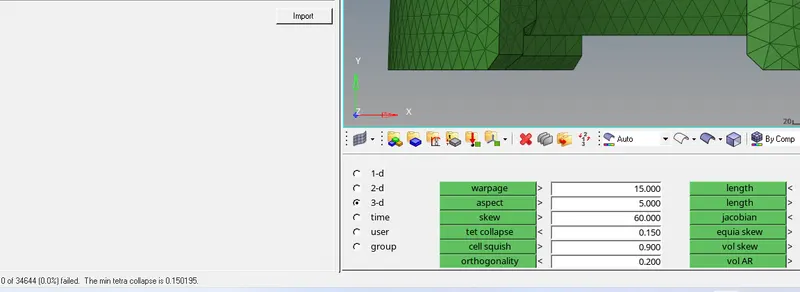
Fig3: Tetcollapse failure
Step2: Firstly, 2d meshing is carried out in the hub folowed by 3d- tetratmesh

Fig4: Tetramesh panel
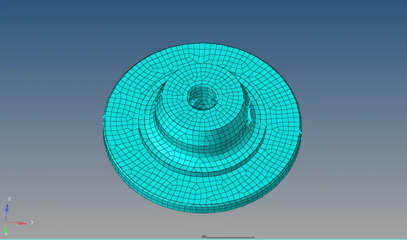
Fig5: Tetrameshed hub
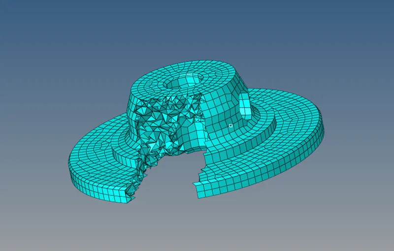
Fig6: Internal view of the tetramesh
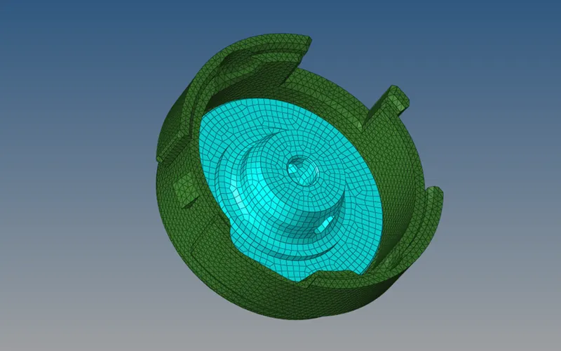
Fig7: Final meshed hub and cover