Assignment 2-RADIOSS Engine File Editing & 3D Meshing Challenge
AIM
1. Check the material properties of the rail component and calculate the speed of sound in steel rail=_______
2. The length of the rail is about 1000 mm.calculate the time takes for a shock wave to travel from one end of the rail to the other.
3.Time for sound to travel length of rail=______
4.Edit the engine file so that the stress wave can be monitored, moving from one end of the rail to the other during impact -this will require a termination time equal to the time it takes for the sound to travel the length of the rail(set on/RUN card)
5.Set the frequency of animation output to a time that will give 20 animation steps(/ANIM/DT)
6.Change /print -10.
7.3d meshing tetra mesh and hex mesh
- Repeat class examples and, maintain the quality.
- Target tet size=5mm,hex size=10mm,tet collapse=0.15.
Solution
- Radioss engine file:
In Radioss there are two files, namely Starter file & Engine file. The starter file contains the information about the model, boundary conditions, etc. In the starter file, the file begins with /BEGIN and the file name (FIRST_RUN in this case).
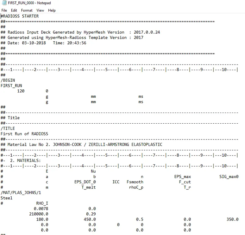
Then there are the units of the quantities for input and output. After that are the material properties such as property card, Young’s modulus, poisson’s ratio, etc.
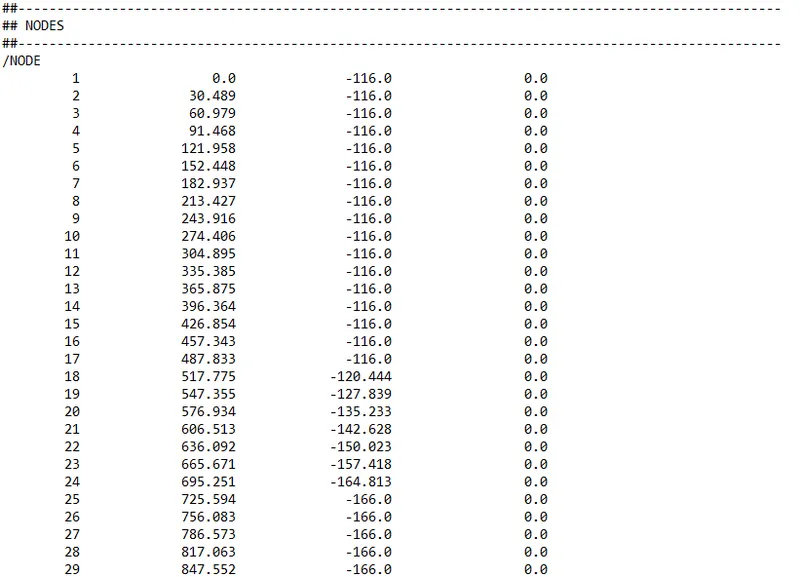
Then there is the node ID & coordinates of the node (x,y,z).
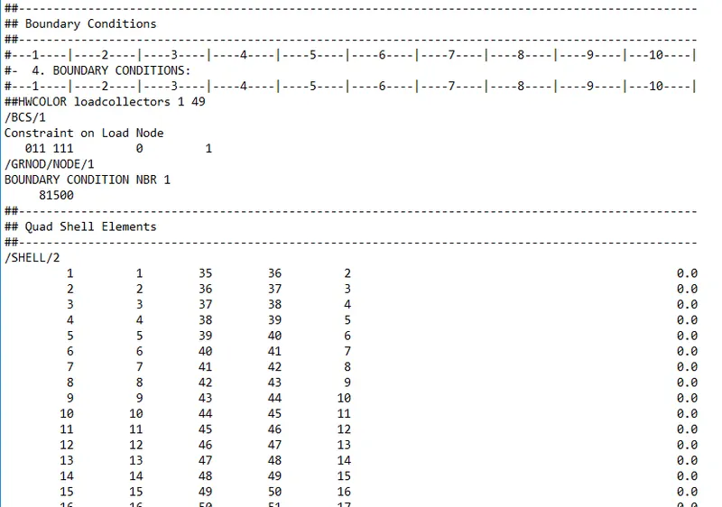
Following that are the boundary conditions.
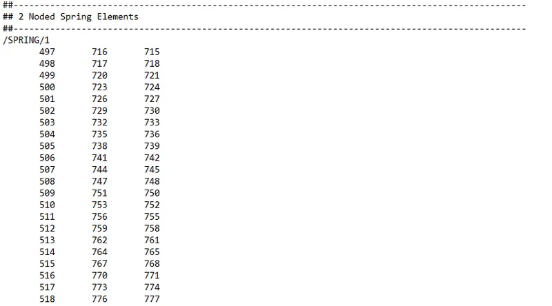
After the boundary conditions, if there are any connectors, their related information is given.
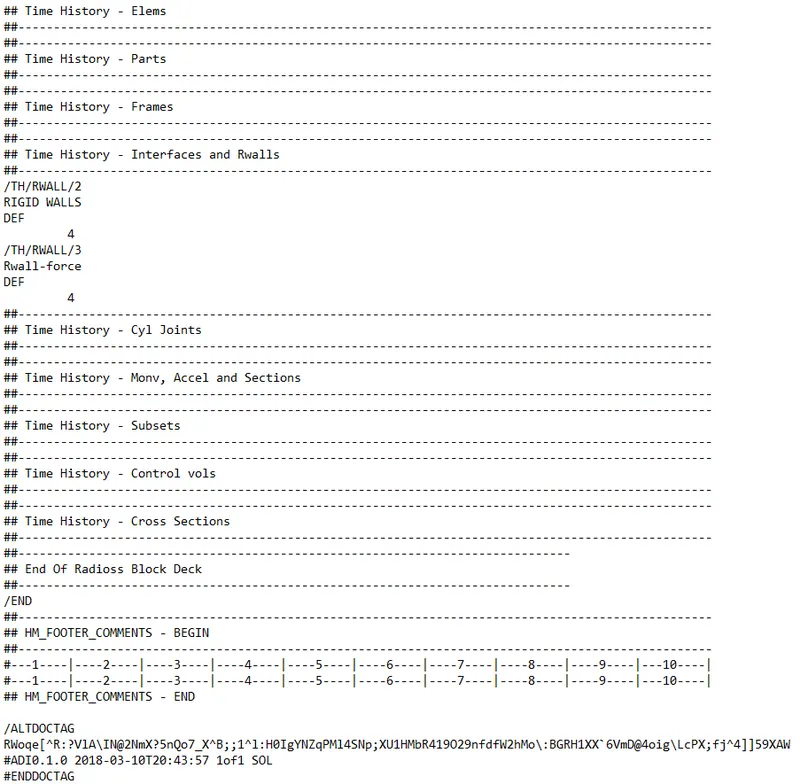
At last, the file is completed with an end tag.
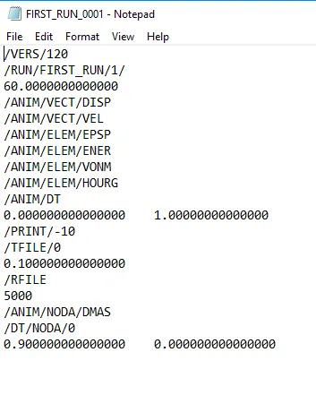
The engine file contains information about the time step and other information.
Calculations:
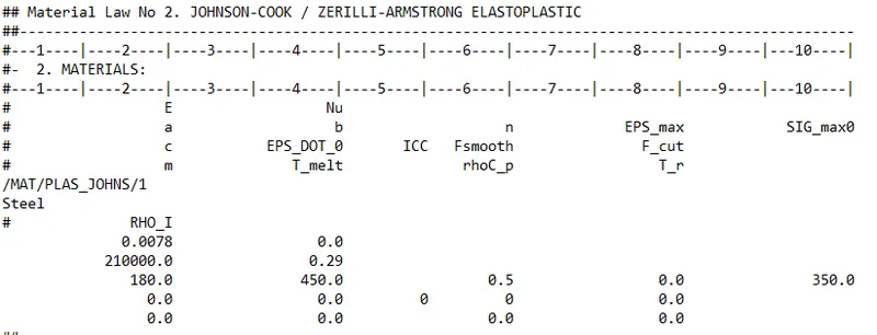
1)
From the material properties,
Density = `0.0078 frac{g}{mm^3}`
Young Modulus ,E = `210000 GPa`
Poisson Ratio , = 0.29
Then speed of sound is given by ,c = `frac{E}{rho}`
putting these value in above equation,
`c = frac{210000}{0.0078} => 5188.74 (mm)/(ms)`
2)
The length of the file is given as 1000mm. The speed of the sound is calculated as 5188.74 mm/ms. The time taken to travel through the rail is
t = 1000/5188.74
t = 0.19 ms
3) Time for sound to travel length of rail = 0.19 ms
Radioss Engine File
4. The termination time is essentially the total time the solving will happen. So it is the time taken to travel through the rail, which is 0.19 ms.
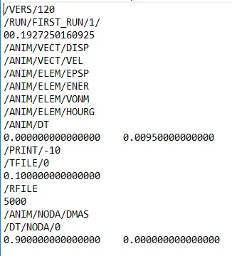
5)
To set the frequency of the animation output, we will need to consider the total solving time. The frequency of the animation output is the time for which every snapshot is taken during the solving. For example, if the frequency is 1, the snapshot is taken for every 1 time unit.
In this case, the total solving time is 0.19ms. To take 20 snapshots, we need frequency as
f = 0.19/20
f = 0.0095
=======================================================================================
6. Tetra Meshing
Procedure
- Import geometry into the hypermesh window. Geomtry consists of two components.
- For first compnents, check for any error in the geometry by geometry cleanup option.
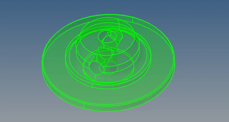
- Remove fillet less than 5 mm by using defeature command in the geomtry menu

- Prepare geometry by using replace point, toggle edge, split surface etc from quick edit panel.

After that 2D meshing is done on the surface with trias element of size 5mm.
After that we checked for failed element quality to fix.
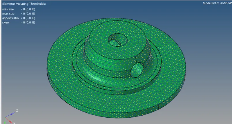
As there is no failed element , next we move on to perform meshing.
We have selected 2D trais element as selection to perform 3d tetramesh .

3D tetramesh of the component is shown below with the help of cut section.
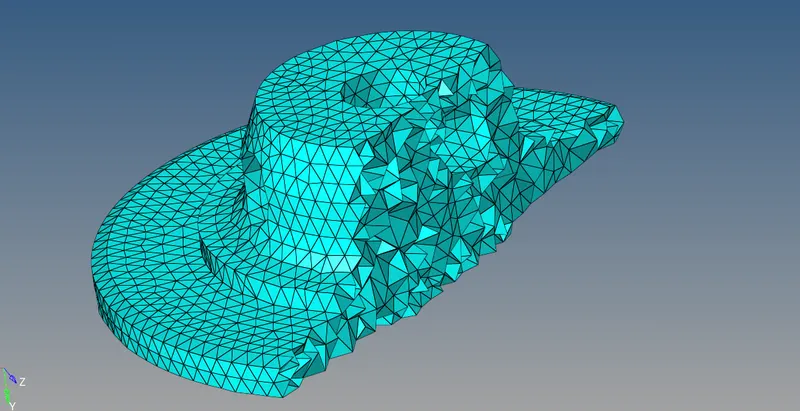
After that we have checked for failed 3D element which doesn't meet the requirement criteria of tet collapse less than 0.15.
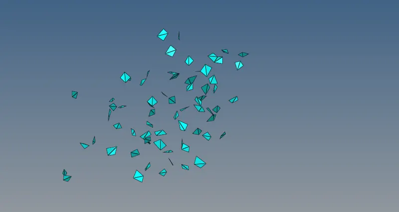
We have found 69 failed elments which is shown below , with the help of mask option.
We have remesh the element with the help of criteria option , and manually adjusted the distance between two element with the help of distance tool.

Component 2:
- Remove fillet less than 5 mm by using defeature command in the geomtry menu
After that 2D meshing is done on the surface with trias element of size 5mm.
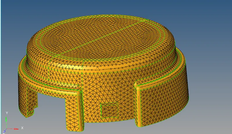
After that we checked for failed element quality to fix.

As there is no failed element , next we move on to perform meshing.
We have selected 2D trais element as selection to perform 3d tetramesh .
3D tetramesh of the component is shown below with the help of cut section.
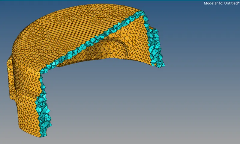
After that we have checked for failed 3D element which doesn't meet the requirement criteria of tet collapse less than 0.15.
We have found zero failed elments in this components.
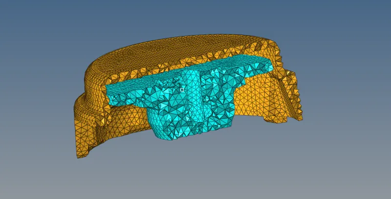
Complete components is shown beow.
========================================================================================
Part-2
Procedure:
- Import:
- Thie given Arm Bracket model is imported using import geometry option.
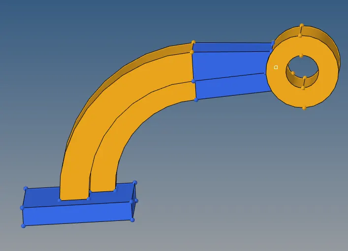
- Meshing:
- Starting from the base component, 2-D elements are created using automesh option uder 2-D tab with hex size of 10 mm.
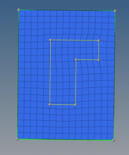
- To obtain 3-D hex mesh, elem offset option under 3-D tab is used.
- The 2-D elements created are selected, thickness, no. of layers and along geometry is selcted under solid layers option.
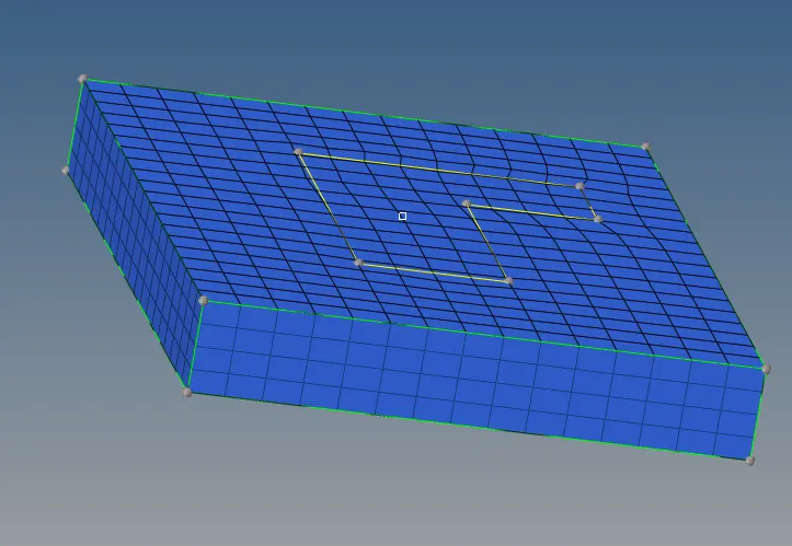
- To mesh the arm_curve part, spin option under 3-D tab is used after masking the hex8 elements created.
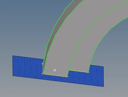
- Spin elems option is selected, with angle = 90deg and on spin = 20 (layers) and 3-D elements are created.
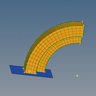
- To mesh on the arm_Straight part, which is having a taper, linear solids option under 3-D tab is used.
- To use linear solids, 2-D elements should be present at the start face of the part. Hence faces option under tools tab is used.
- The 3-D elements on the arm_curve is selected and face is created.
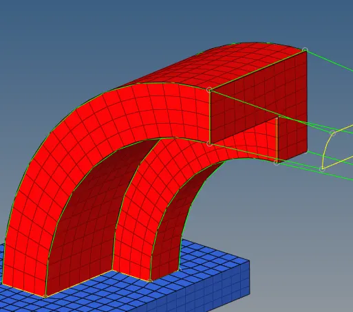
- In case of linear solids option, there should be start elements as well as destination elements. So destination elements are created using automesh option under 2-D tab with node orientation matching with the start elements.
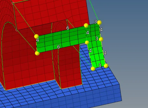
- Creating the 3-D mesh with linear solids option.
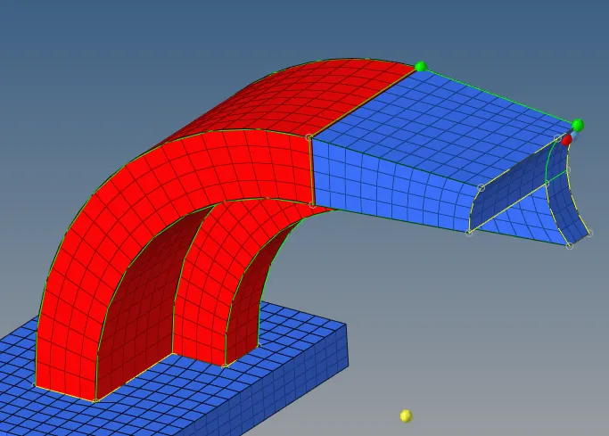
- The remaining part to be mesged is the boss.
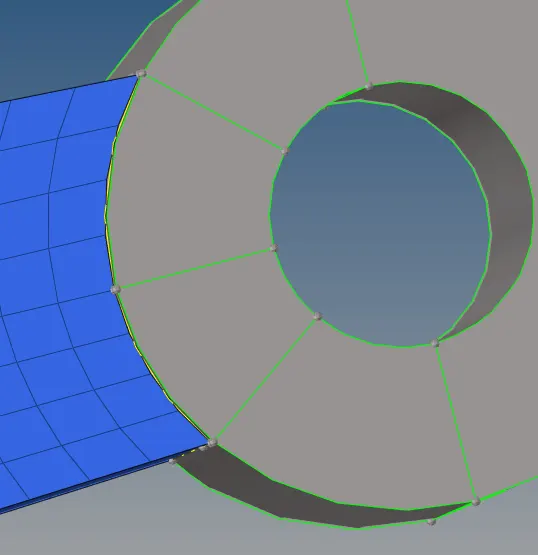
- Meshing the top surface with 2-D elements using automesh option.
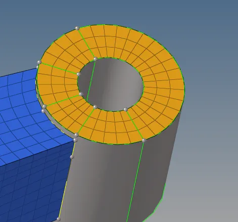
- After 2-D elements are created, a node which is normal to the present element nodes are created on the bottom surface of the boss.
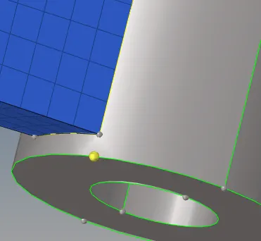
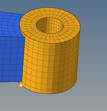
- Now using solid map option under 3-D tab to obtain 3-D hex mesh on the boss.
- The elemenst created by solid map is stored under new collector(solid map) which is moved to boss using organize option.
Conclusion:
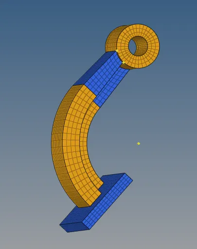
Hence 3-D hexa meshing of the arm bracket is carried out by using various options (elem offset, Linear solid, Solid Map, Spin)under 3-D tab
====================================================================================
Conclusion
- The given challenge has been successfully performed.
- 3D Meshing of both component has been successfully performed.