Assignment 2
AIM:
( 1 ). To calculate the speed of sound and time of steel rail by using material property.
( 2 ). To apply 3D mesh for Arm_bracket and Housing components.
( 3 ). Practise the 1D element for the given component.
KEYWORDS: Tetra mesh, Hexa8, Beam, Truss, Spring, Speed of Sound, Youngs modulus, Density etc.,
SOFTWARE: Hypermesh
OBJECTIVE:
( 1 )
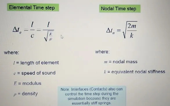
- By taking Youngs modulus and Density value calculate speed of sound using the formula,
- After calculating the speed of sound, easy to calculate time required to travel speed of sound of steel rail.
( 2 )
- For Housing component, tetra mesh is applied based on quality criteria.
- For Arm_bracket, Hexa mesh is applied based on the quality criteria.
( 3 )
- For the given component 1D element is applied like, RBE2, RBE3, Beam, Truss, and Spring.
- For the same component weld is performed like Spot and Seam weld.
INTRODUCTION:
(1)
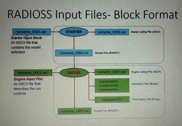
Altair RADIOSS is a multidisciplinary finite element solver developed by Altair Engineering. It can solve both linear and non-linear problems. It is a finite element solver using implicit and explicit integration schemes for the solution of engineering problems, from linear statics and linear dynamics to nonlinear transient dynamics and mechanical systems. This multidisciplinary solver enables designers to maximize performance related to durability, NVH, crash, safety, manufacturability, and fluid-structure interaction, in order to bring products to market faster. RADIOSS analysis capabilities for linear and non-linear finite element analysis, sheet metal stamping, and multi-body dynamics are accessible via two input formats.
CALCULATIONS:
a ). Calculating Speed of Sound:
c = sqrt(E / Rho)
where,
c = speed of sound (mm/sec)
E = Youngs modulus (N/mm2)
Rho = Density (kg/mm3)
c = sqrt(210e3 / 7.8e-6)
1 Kg = 0.102 N
c = sqrt[(210e3 * 0.102) / 7.8e-6]
c = 52403.75 mm/sec
b ). Calculating Elemental time step:
Delta_te = l / c
where,
l = length of the rail in mm
c = speed of sound in mm/sec
Delta_te = 1000 / 52403.75
Delta_te = 0.019 sec
for calculating each time step frequency,
Delta_te = 0.019 / 20
Delta_te = 0.954 ms
Engine File Snippet
/ANIM/DT
# TSTART TFREQ
0.000000 9.540000E-04
/PRINT/-10
/RFILE
# NCYCLE IREAD IWRITE
5000 0 0
/RUN/FIRST_RUN/1/
0.190000E-01
/TFILE/0
# dT_HIS
0.100000
/VER/120
/ANIM/VECT/DISP
/ANIM/VECT/VEL
/ANIM/NODA/DMAS
/ANIM/ELEM/EPSP
/ANIM/ELEM/ENER
/ANIM/ELEM/VONM
/ANIM/ELEM/HOURG
/DT/NODA/0
0.9 0
(2)
For the given Housing and Arm_bracket component 3D meshing is performed based on the quality criteria. For Housing component, tetra mesh is applied and for Arm_bracket, Hexa mesh is applied. The quality criteria as given as Target tet size=5mm,hex size=10mm,tet collapse=0.15. Initially for the Housing component 2D mesh (trias) as been performed with element size as 5mm and after the 2D mesh 3D mesh is performed by using tetra command from 3D by keeping the tet collapse as 0.15. For Arm_bracket, 2D mesh (Quad only) is performed and converted that 2D element to 3D by using Solid map, Linear solid, element offset, spin commands etc.,
( i ) . Housing component with 2D & 3D meshing: For the hub and cover part 2D meshing as been done by trias with element size as 5mm. After done with 2D meshing, tetra mesh is performed for both the parts which defines 3D unstructured mesh as shown in Figure (2 , 4).
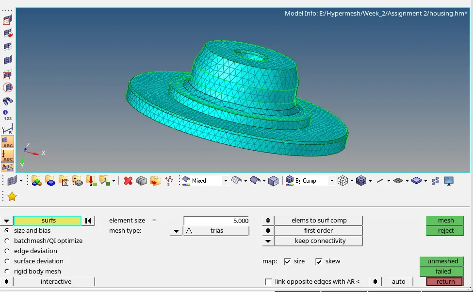
Fig 1: 2D meshing of Hub part
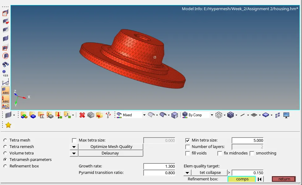
Fig 2: 3D meshing of Hub part
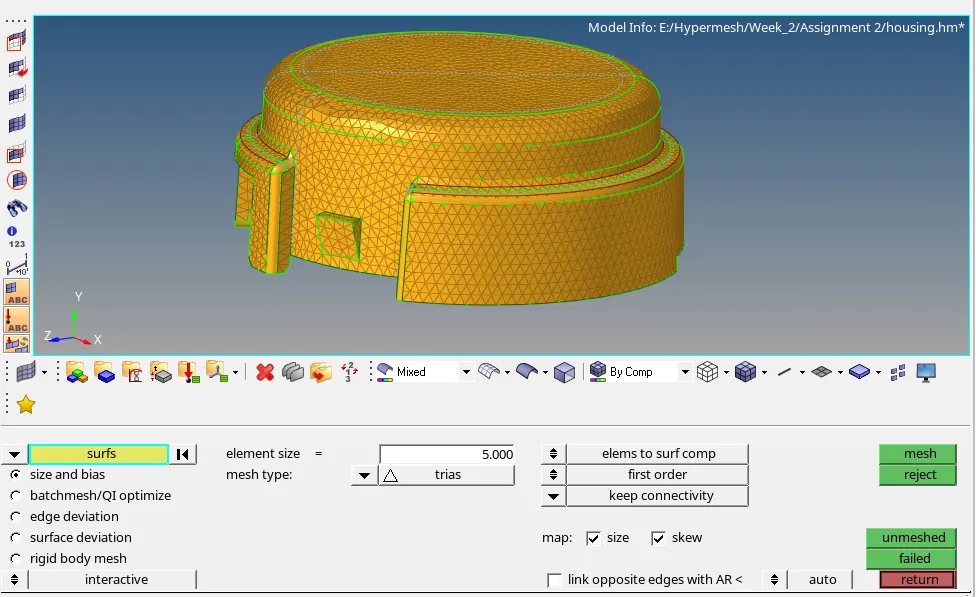
Fig 3: 2D meshing of Cover part
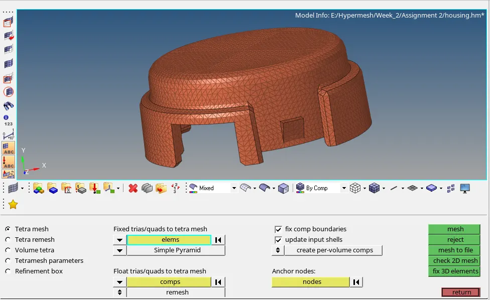
Fig 4: 3D meshing of Cover part
( ii ) . Arm_bracket with 2D & 3D mesh: For this assembly component is sub divided into 4 parts as Base, Arm curve, Arm straight & Boss. For the base part, 2D mesh (Quad only) is performed on the top surface by converting that 2D mesh into 3D by configuring the element to Hexa 8 with size of 10mm. For converting into 3D mesh, element offset is used by selecting the top surface element and modify the parameters like layer, thickness as shown in fig 5. For the Arm curve part, spin command is utilized by selecting the L-shaped element presented over the base surface and modifying the parameter like angle, spin etc., as shown in figure 6. For the Arm straight part, duplicate faces is created from the arm curve part for reference and linear solid command is used which reflect the elements to overall the part of arm straight by indicating the node from reference and current part as shown in fig 7. For the Boss part, Solid map is performed by creating the 2D element for side face and taken as reference which reflects to overall part as shown in fig 8.
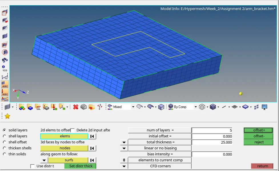
Fig 5: Base part
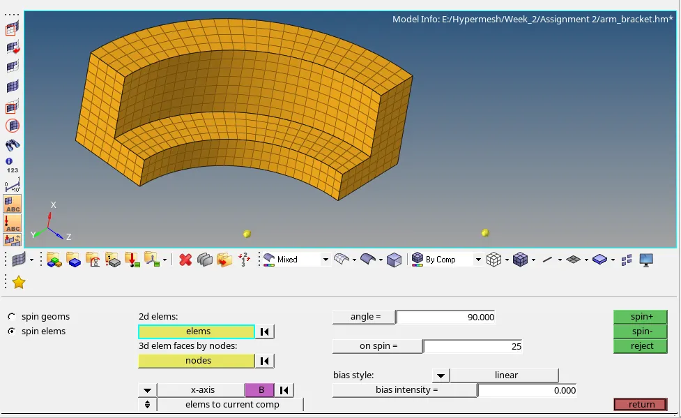
Fig 6: Arm curve part
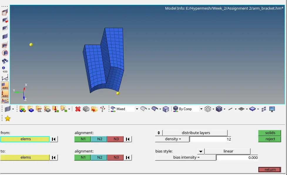
Fig 7: Arm straight part
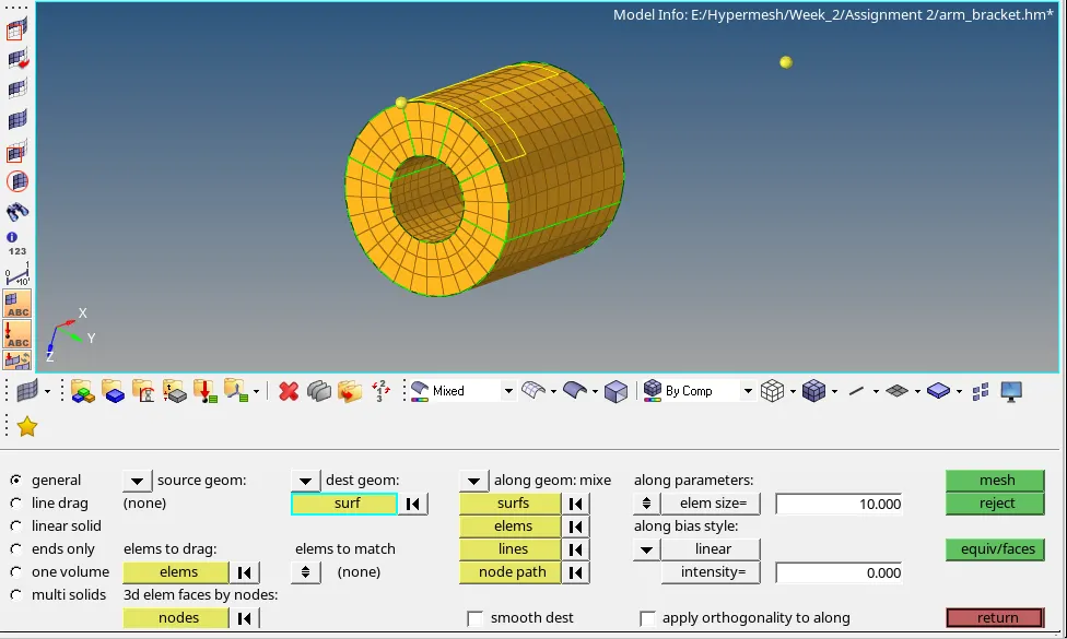
Fig 8: Boss part
(3)
For the given component 1D element, Spring, Rigid (RBE2), RBE3, welds (Sppot & Seam) is performed. The following 1D element types,
- CRod
- CBar
- CBeam
In brief, CROD elements support (allow) tension and compression only, whereas CBARS and CBEAMS
allow bending as well. A CBAR element is a kind of simplified CBEAM element and should be used
whenever the cross-section of the structure and its properties is constant and symmetrical. The CBAR element requires that its shear center and the neutral axis coincide. Due to this requirement CBAR elements are not useful for modeling structures that may warp, such as open channel-sections. This limitation is not present in CBEAM elements. Thus, CBEAM elements are used to model more complicate -d geometries with varying cross-sections. Important to note, in CBEAM elements the neutral axis and shear center are noncoincident. Overall, this type of element demands a deeper understanding of beam theory.
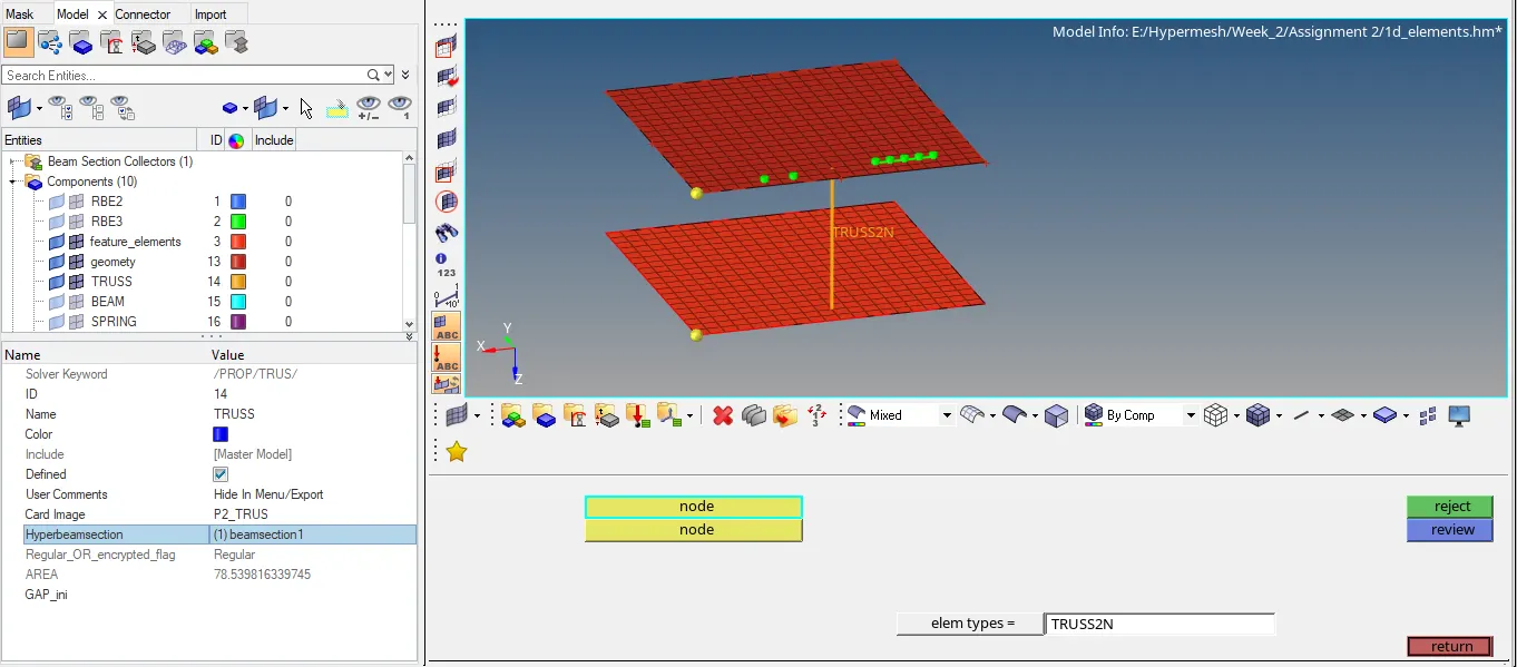
Fig 9: Truss with Property
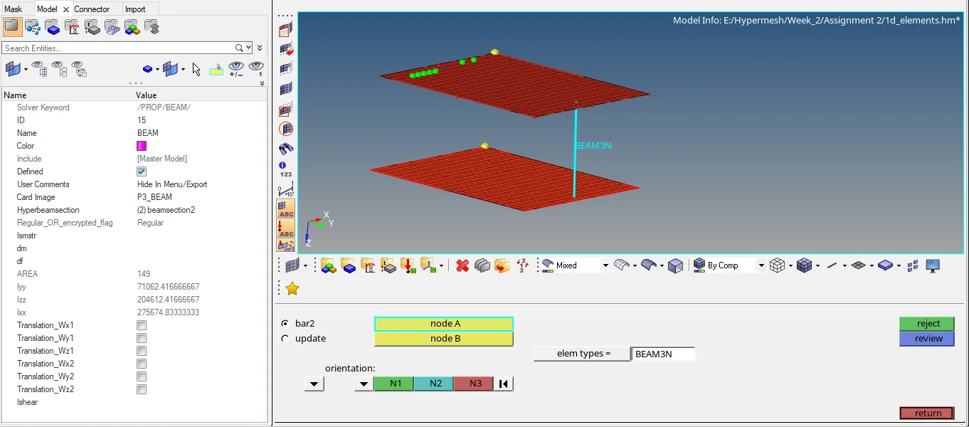
Fig 10: Beam with Property
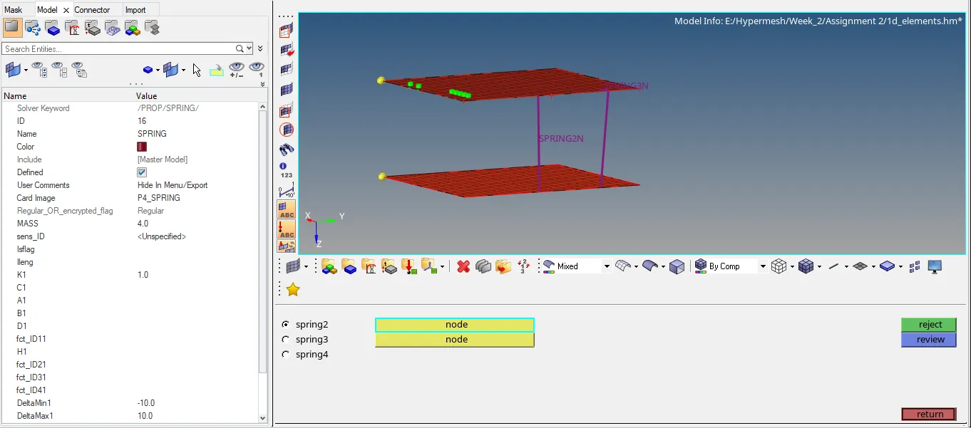
Fig 11: Spring with property
RBE2: Rigid link to transfer motion from the independent node to the dependent node (s) in the same amount.
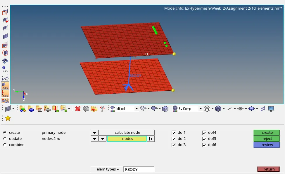
Fig 12: RBE2 Connection
RBE3: Rigid link to distribute loads will not include stiffness.
- The motion of a dependent node is defined as the weighted average of the motions of a group of independent nodes.
- Typically used to distribute loads applied on the dependent node amongst the selected independent nodes.
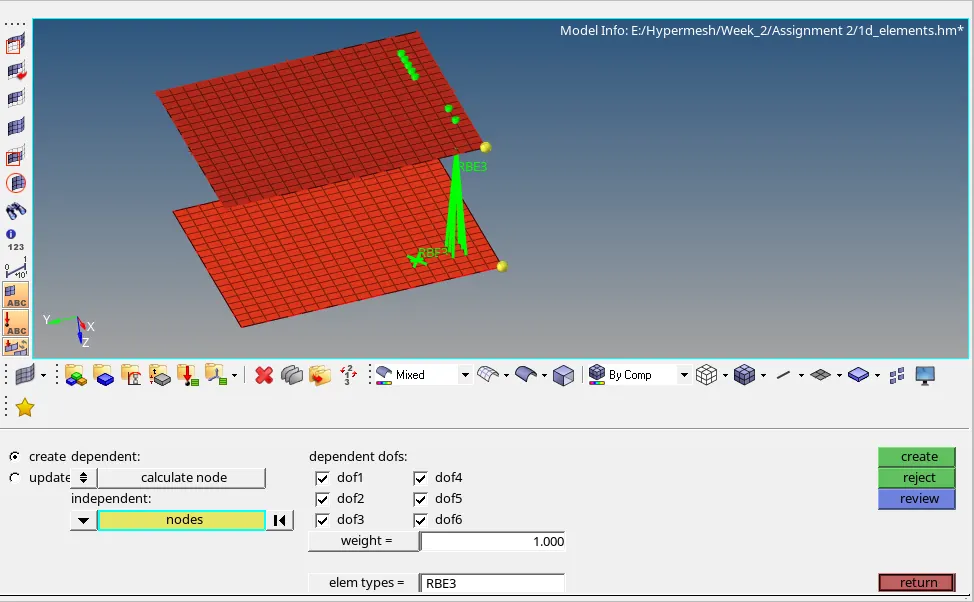
Fig 13: RBE3 connection
Welds: In general the weld is performed by node space distance, panel distance as tolerance as mentioned and shown in figure 14 & 15 .
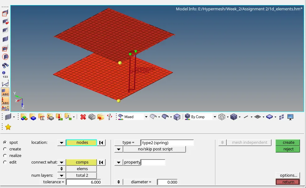
Fig 14: Spot Weld
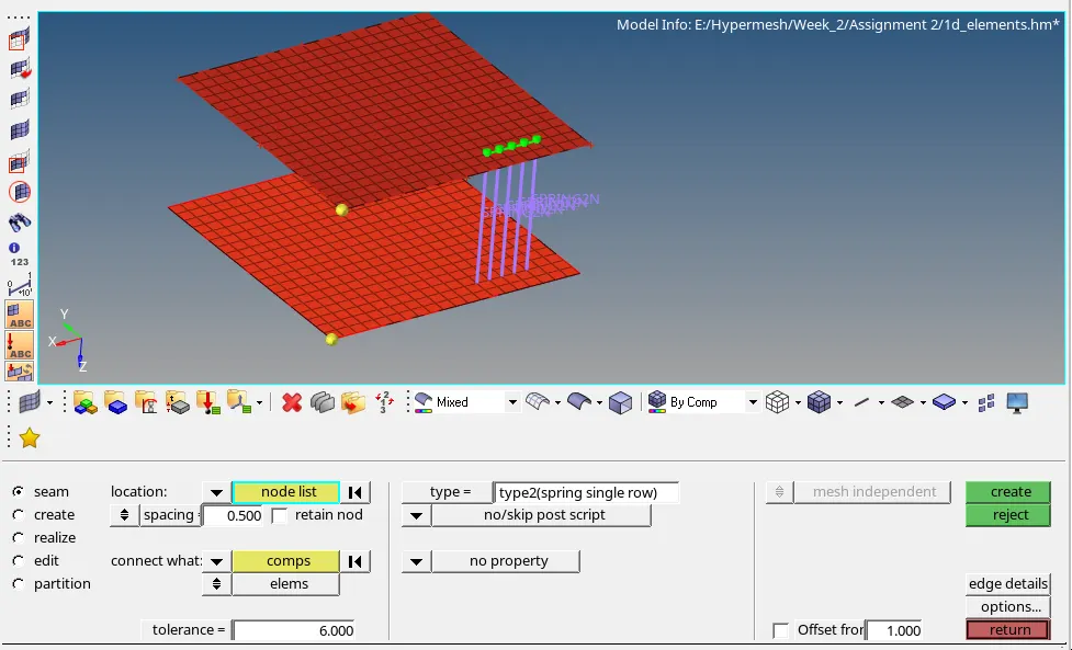
Fig 15: Seam Weld
RESULTS:
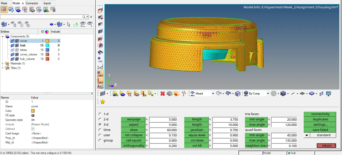
Fig 16: Housing
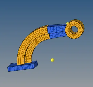
Fig 17: Arm_bracket Assembly
CONCLUSION:
1. Calculated speed of sound and elemental time step of the steel rail.
2. Performed 3D meshing tetra and hexa for Housing and Arm_bracket respectively.
3. Performed 1D element, Rigids, Welds for the given component and as shown in figure (9-15) .
DRIVE_LINK:
https://drive.google.com/drive/folders/1U748DC3Vjp2yasyEw7I-lGlytFKuRCbj?usp=sharing