Assignment 2
AIM:To get a 3D meshing to a given various component and the meshing involves in it to be a tetra mesh and a hexa mesh.
PROCEDURE:Firstly we have the various questions involved previous to the meshing of the model those are:
(1)Check the material properties of the rail component and calculate the speed of sound in steel rail:
Ans: The material property of steel having density(RHO)=0.0078gm/mm^3 =7800kg/m^3 as per the data given in the RAD file of 0000 file.
The speed of the sound(C)=√ (E/RHO) where E=Young's modulus =210GPa(given)
C=5188.74m/s=5188.74mm/ms
(2)The length of the rail is about 1000 mm.calculate the time takes for a shock wave to travel from one end of the rail to the other.
ANS:Time Taken(T)=L/C where,L=1000mm=.1m
T=.1/5188.74=0.0000192725sec=.0192725ms
So the propogation time will be same as stated above.
(3)Time for sound to travel length of rail=time taken to propagate the wave upto the end of rail.
i.e T=0.0192725ms
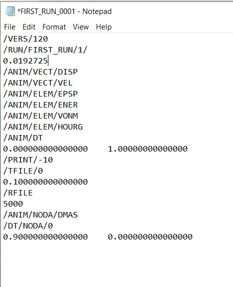
(4)Edit the engine file so that the stress wave can be monitored, moving from one end of the rail to the other during impact -this will require a termination time equal to the time it takes for the sound to travel the length of the rail(set on/RUN card)
ANS
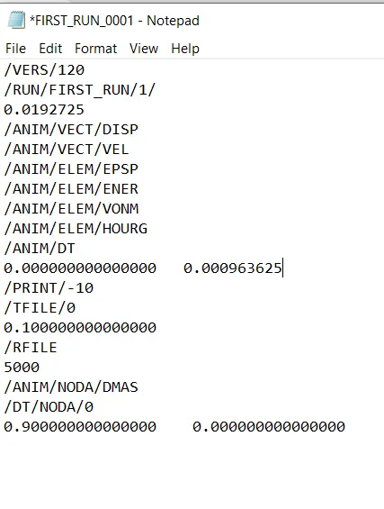
(5)Set the frequency of animation output to a time that will give 20 animation steps(/ANIM/DT)
ANS:Frequency(f)=Time taken/no. of animation steps=0.0192725/20=0.000964miliHz
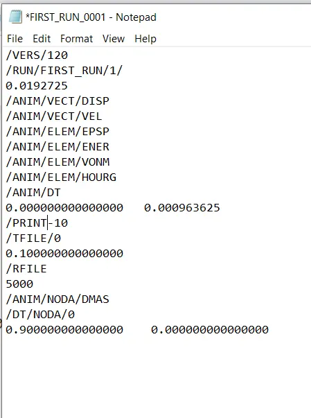
(6)Change /print -10.
(7)The following steps required for following the tera mesh on a given component with given quality criterion:
(a)Using 2D option we have the automesh under element size choose to be a 5mm and using trias only we can mesh the hub and the cover portion ,now doing a volume mesh we have 3 ways in which 2 ways are under 3D tetra mesh.
(i)By using tetra mesh ,firstly needs to change the tetra mesh parameter in which tet collapse should be .15 and minimum tetra size taken as 3mm then going back to tetra mesh mode and deployed the mesh in it .Then using F10 in 3D MODE we can check the tet collapse failure .
(ii)After making a changes in tetra mesh parameter as stated above directly goes to volume tetra changing element size to 5mm and then deployed the 3D mesh.
(iii)Last one going to VIEW>BROWSER>HYPERMESH>UTILITY under it we choose a quick tetra mesh again mesh size choosen to be 5mm in volume complist we can select the component taken for tetra mesh and then clicking on mesh tetra mesh will be assigned.Then we gotta go for tet collapse check ,if we might be getting any error we gotta go for tetra remesh or else manual method can be opted as well which is a quite time consuming.
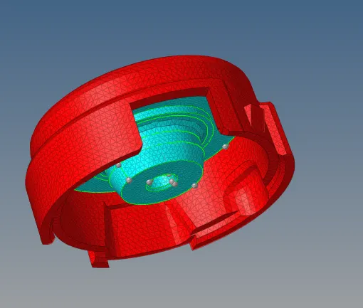
using mask F5 we can see our following results as follows:
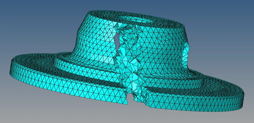
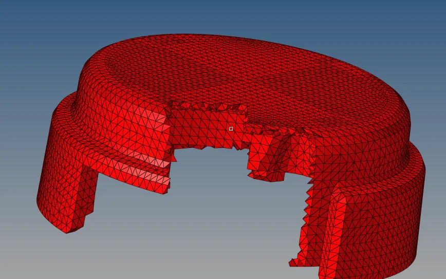
In both hub and cover tet collapse failure are zero ,so we can say that tetra mesh is quite fine.
(b)The model which we have given for hexa mesh involves various procedure as follows:
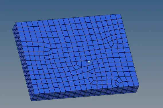
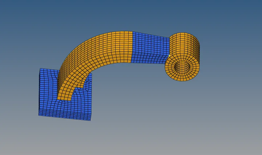
Firstly the BASE part for that we going to automesh in 2D ,element size is 10mm using quads only we mesh the top surface of it then in 3D element offset is being choosen in solid layer ,no. of layers taken as 5 and total thickness taken as 25mm doing offset + we have got the hexa mesh in the base part which is shown:
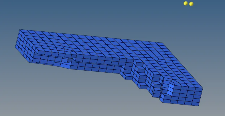
Now moving to the arm curve region,we choose a arc length to assign three different points randomly in it for that we choose F5 three nodes option then applying for circle centre a point gets created after that we gotta go for spin in 3D mode in spin element the angle given as 90 degree axis given as x-axis then in 2d elements we choose all base elements which we have to taken for spin then spin- will give us the hexa mesh in arespective region shown below:
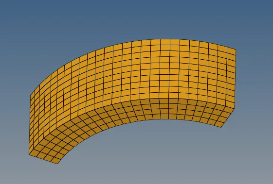
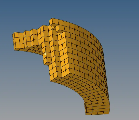
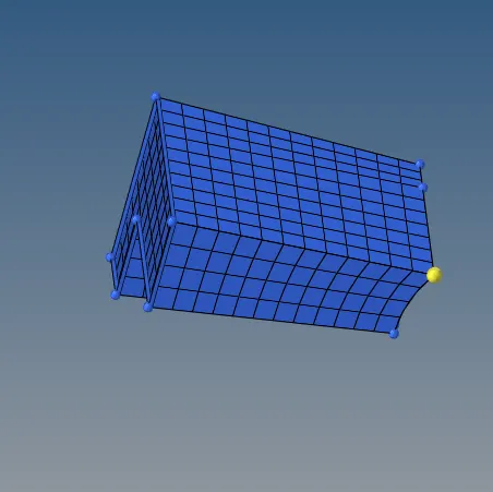
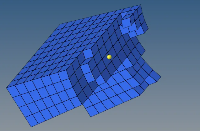
And then in arm straight we choose the outer straight part and mesh using automesh with quads only, elements size could be 10mm ,then we go for linear solid in 3D mode we choose the source surface then we choose the outer surface by making box selection and under alignment we choose random 3 points of source surface and at the outer surface we have to choose the same points as well now clicking on the solids our hexa mesh gets created
Now lastly we now move onto the boss region the top surface will be meshed using automesh with quads only then we create more nodes in it such that rotating quads can be eliminated after we go for the 3D mode in it solid map will be choosen in general mode source geometry is choosen as none then in elements to drag we choose the destination surface of boss and we can choose the node paths as well then we hit mesh and the mesh got generated in the boss region.Images shown for boss
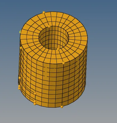
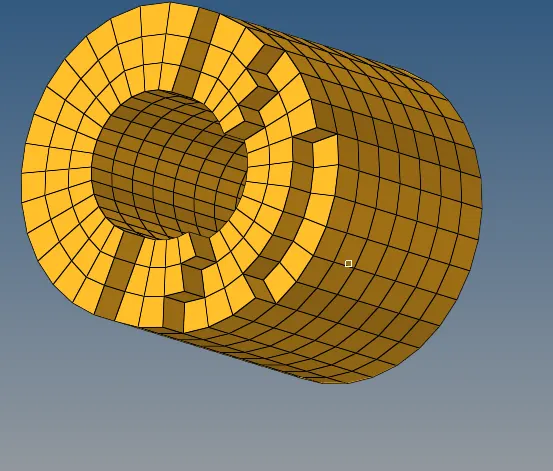
Always we need to keep in mind to use the move option otherwise the components will attached with each other and show dissimilarities .The whole hexa meshing model are shown below:
CONCLUSION:(A) From this we gotta realised how to use the rad files and how to recognise the values which are inbuilted in it to make a further calculations.
(B)Also the models are given in it builts the capability to learn the tetra mesh and hexa mesh with a given quality criterion.