Assignment 2-2 D meshing of the given component
AIM:
-To calculate the speed of sound of speed for a rail componenet,time taken by the shock wave to travel from one end of rail to other also to find out the frequency of animation.
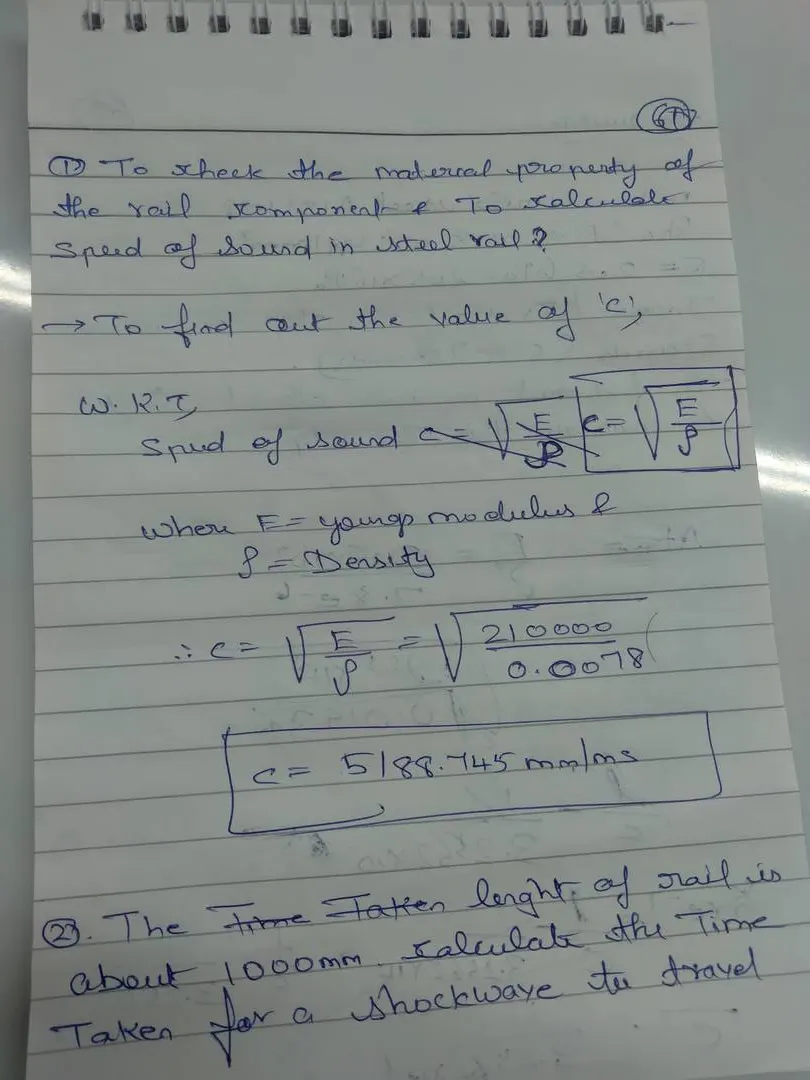
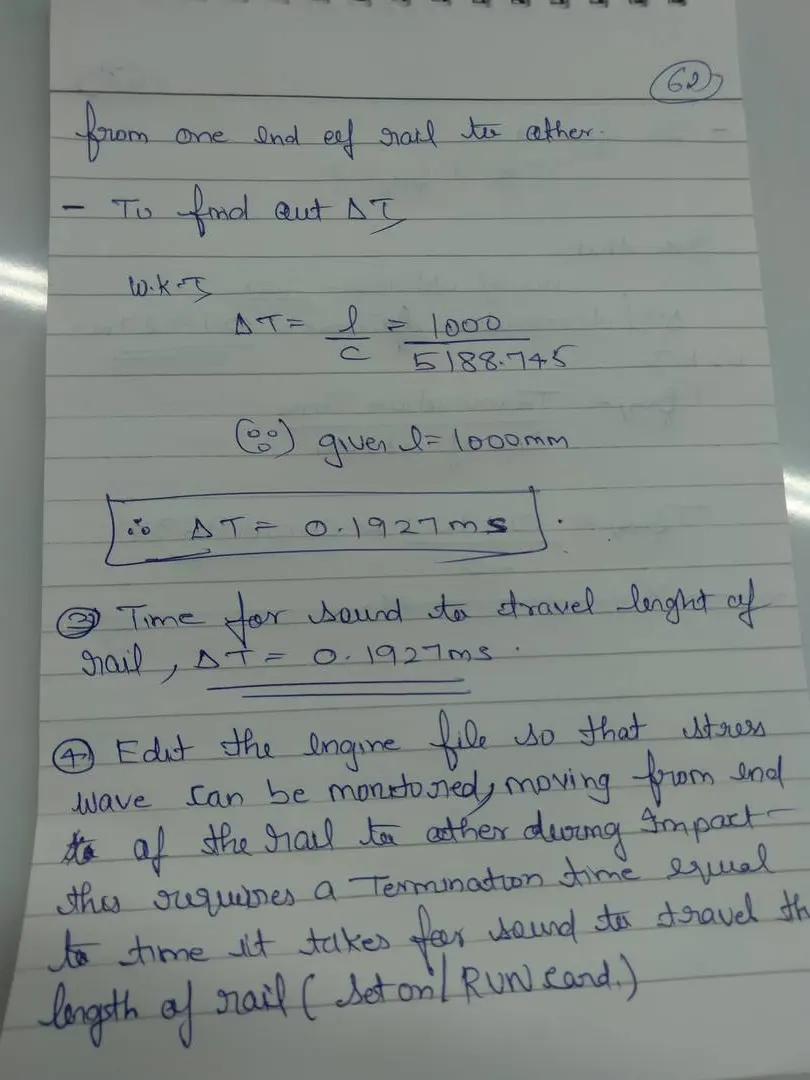
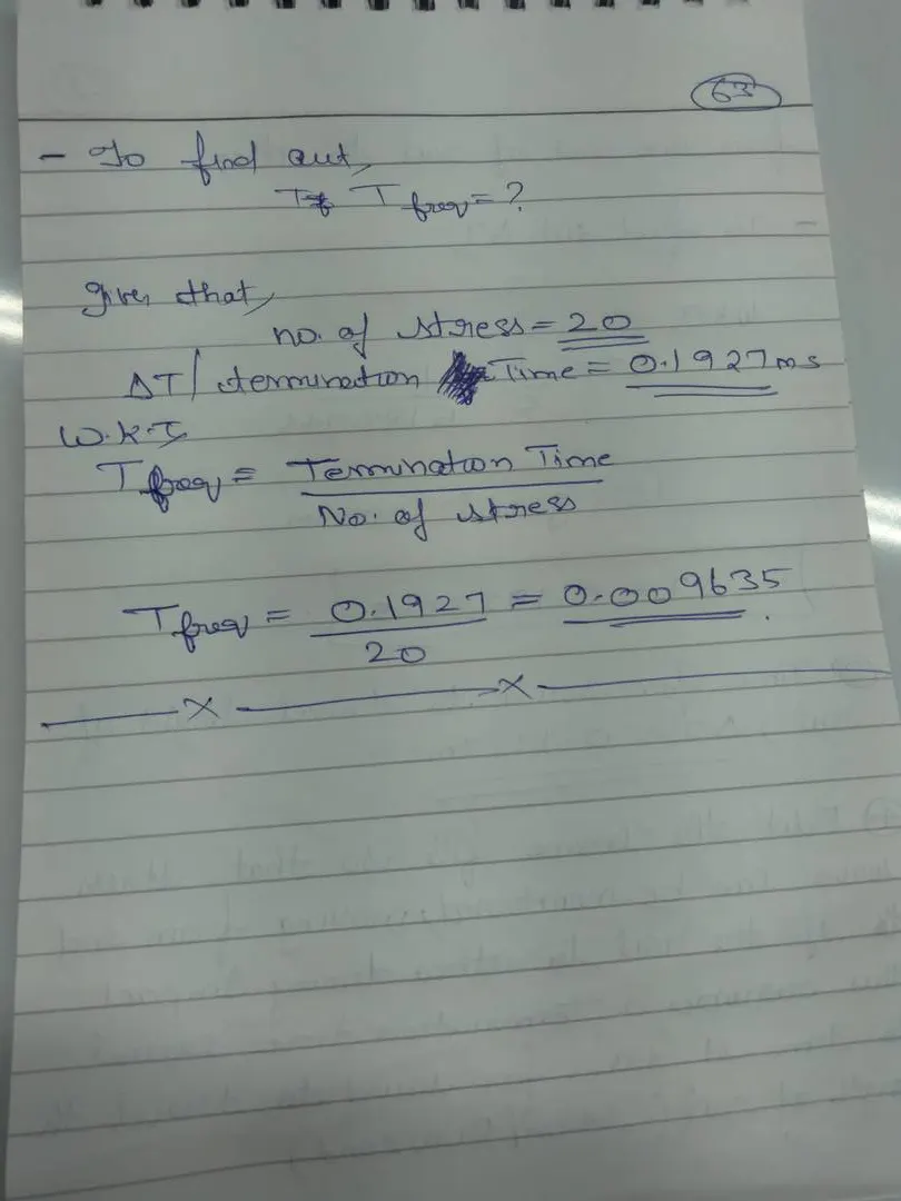
-Edited engine file is given below:
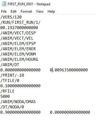
-Here the new frequency is 0.00963500000000 and the new time step will be 00.1927000000000
7)3D meshing tetra mesh and hex mesh
AIM:
-To check the element quality for the given component with given parameters and to perform 2D meshing on the given model.
Solution:
-The 2D meshed component are given below:
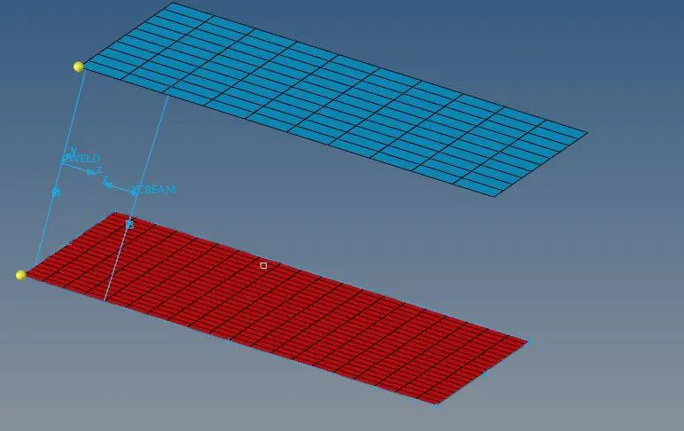
-The check paramter values for the above model is given below:

-Steps followed is given below:
-After opening the model >initially we have to check for any free edge parameter,in case if it is there we have to geometry clean it up.
-after geometry clean up, go to 2D panel>auto mesh >elements >all>after giving the element value>click>mesh.Now here the model will get meshed up.
-Now to check the parameter , we need to click on the check button icon and we can change the paramter value as per our requirment.
-Now we have to create 1D element between 2 meshed surface and this is done by using the option main menu page>1D.
-Now we have to select rods and elemnet type as C-weld.And now we have to select 2 oppoiste nodes anywhere on the shell element and this will create a Cweld element between them.
-Similarly the same step is carried out for beam element too.
AIM:
-To do 3D meshing for the given componenet using hexa and tetra mesh.
Solution:
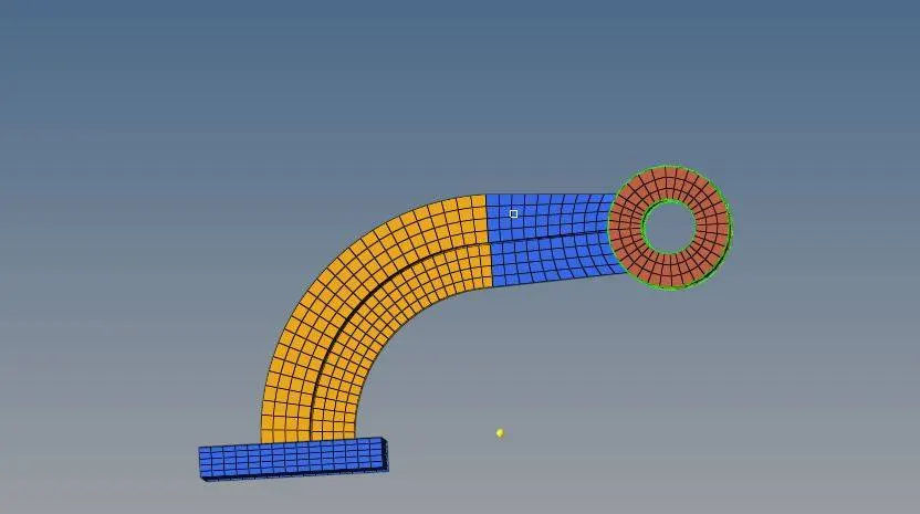 Front veiw
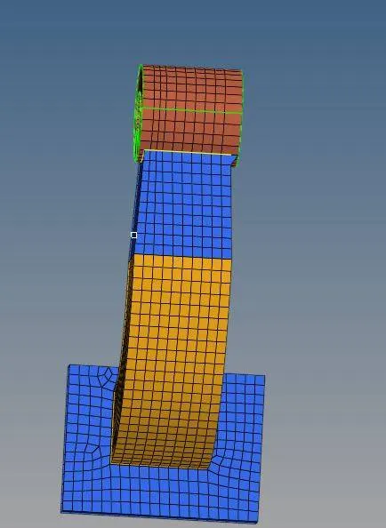 Top veiw.
Steps followed were the following:
-Initially we have to create a 2D mesh and here we will hide the rest of the component by selecting the component and right click and select hide.
-Now we need to press F12 key and need to give element size ,now select the element and press mesh (in mesh type give quads only not tria).
-Now we need to do some solid meshing on the base component.
-Now after creating shell mesh we need to choose the element offset and select solid layer.
-Select the element>all and On geometry to follow choose "surface" after selecting 2 surfaces.
-Here we can also give value to the "number of layer"option,inorder to get an appropriate mesh.
-To check the distance or thickness of a particular component we make use of disrtance option by using F4 key>select two points>distance ,now we will get the distance dispalyed.
-Now to mesh a thin solids which are essential of thick shells,like sheet metal ,composites or molded plastic componenets. we make use of "offset" optiion.we can do it by using the option element offset>select the surface>'offset+'.
-Now select the other element,here we need to remove only the 3D elements for doing this we need to go for mask element option(F5 Key)>configure>select hexa type.
-NOw under displayed option select entities>mask(here we have only 2D left)
-For curved geometry>make use of spin option>spin element>spin angle =90degree>On spin=25.
-Now we need to create a center pointon axis we use F4 key>three nodes>Drag the mouse on one point where we get to see one point formed at a particular side of component and there by we can other 2 nodes.
-Now we get a cricle center(we select it as a base point,To get a base point >2D element>select the elements(shift+mouse click)>duplicate.
--Now we make use of linear solid option and here we make use of 2D option>tools>face>components.
-Next go to linear solids>3D element (here to get destination element we use f2 key).
-2D option>automesh>chooses spin+ or Spin - as per our requirement.
-Now for Boss part we need to go for solid option where we need to give our source and destination geometry (for getting this we need to use the opition F12>surface>select surface>mesh.
-To set an offset for the geometry we use the option Shift+F7>project>select the node on top of source geomerty and click on 'Off set +/offset - 'as per our requirement.
-finally after we remove the 2D geometry elements the model become free of unstabilised geometry.
Model 3:
-To create a 3D tetra mesh for the given component with target element size of 5mm.
Solution:
-Initially we have to import the model in hyperworks format.
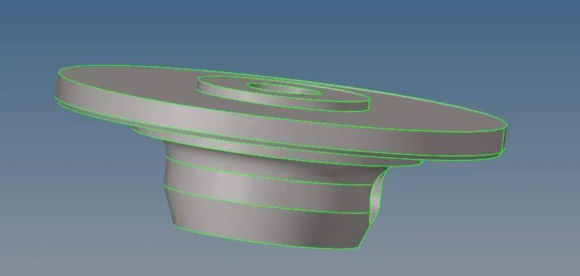
-Initially we have to hide the cover and set hub as a current component.Now we have to perform 2D meshing on hub using trias only.2D>automesh>size and bias>surface.give element size as 5mm and click on mesh.
-
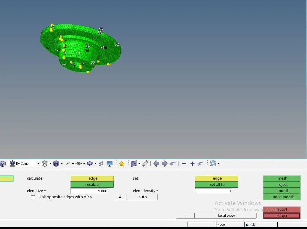
-Now we have to create a tetra mesh on hub with thye help of 2D shell element,for this we have to go to main menu>3D>tetra mesh,select dispalyed element and click on mesh.Before performing tetramesh we have to set the tetcollapse element with values under tetramesh parameter.


-Now we have to do masking process to check whether the element is 3D tetrameshed.
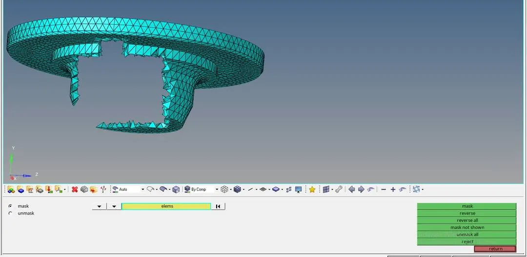
-Before doing masking process we need to remove the 2D shell element.and that is done by using the optioin Press F2>select elements>select configuration>tria3>select entities and delete.
-Now we have to hide the hub and select the cover as current model.
-Here instead of doing 2D mesh ,wee can dierectly go for 3D tetra mesh (option:3D >volume tetra),now select the surface,set the element size,give 2DE type as trias and 3D as tetras.
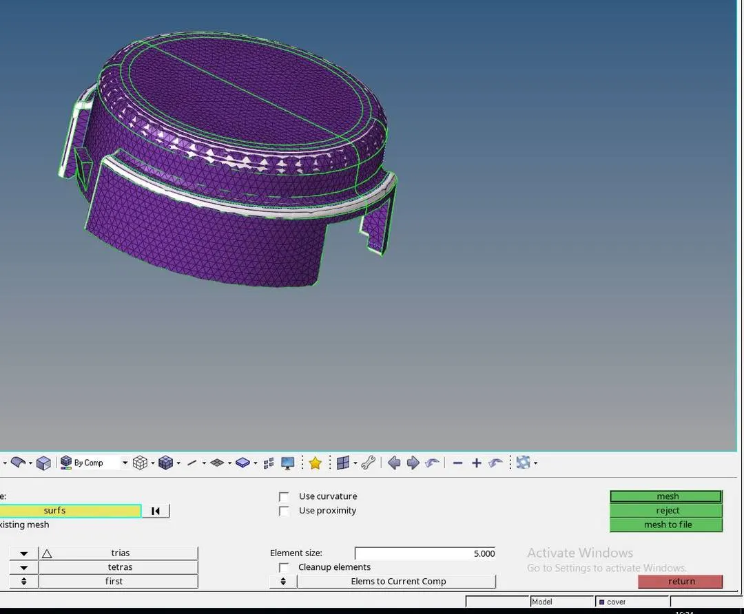
-Now we need to do masking to check whether the element is 3Dtetra meshed or not.Press F5>mask>select element>with the help of mouse and shift key and select masked.
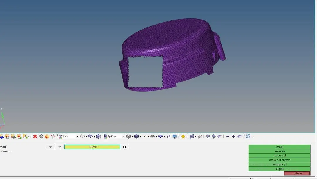
-Now we get a masked element model which shows us that the the above elements are propely 3D meshed.