Assignment 2
OBJECTIVE:
- To perform 3D tetra meshing on the given housing model
- To perform 3D hexa meshing on the arm bracket model
- To create 1D elements in the given model
- To understand the given radios text files and answer the given questions
SOLUTION:
- 3D Tetra meshing
The objective of this project is to create 3D tetra mesh for the given model, with an element size of 5mm and tet collapse value of 0.15. There are multiple ways to create a 3D mesh for a model. The easiest method to create a 3D mesh is to use the Volume tetra option in the tetramesh tab in 3D panel. Both solids and surfaces can be meshed using this method and mesh is generated based on the element size given. However, this method does not guarantee to generate a mesh always and will depend on the model design. Also, the mesh formed is entirely computer generated and may lack in quality. This is preferred when the CAE engineer has to create a meshed model in the least amount of time. The second method is to use the Quick tetra mesh option. To use this option, go to View → Browsers → Hypermesh → Utility → Geom/Mesh → Mesh tools → Quick TetraMesh. Similar to the first method, this generates a 3D mesh based on the input values given. This method too gives less control over the mesh quality and is used when the engineer has limited time. The final method to create a 3D mesh is to convert an existing 2D mesh into 3D. The 2D mesh can be generated using the conventional methods and tools provided Hypermesh. This gives good control over the quality and flow of the mesh since the mesh can be modified as per the need of the engineer. Once the 2D mesh is made, it can be converted into a 3D mesh using tetramesh tab in 3D panel. In tetramesh, select all the elements to be converted, select the mesh type and press mesh. This will convert the 2D mesh into 3D mesh. This method is time consuming, but gives good control over the mesh quality. Further, tetra remesh option helps to modify the existing 3D mesh into mesh of required quality criteria. After creation of mesh the quality and mesh parameters can be checked using the Check elements option in Tool panel.
Step 1:
Open the models and analyse them in detail. The aim is to identify clean-ups required in the geometry and make necessary changes. Eliminate unwanted free edges, duplicate surfaces and modify or eliminate negligible features.
Step 2:
Decide the method to be used to create the 3D mesh. A 2D to 3D conversion is preferred method, when the geometry is complex and enough time is available, otherwise try using volume tetra mesh. If it doesn’t generate the mesh, use quick tetra mesh method.
Step 3:
To create the 2D mesh, decide on the target element size, min size and maximum size. Once the element size is finalised, modify the features in the model so that the least number of element fails the quality criteria. Create the 2D mesh using the automesh option in the 2D panel and modify the elements for quality criteria. Once the 2D mesh satisfies all quality criteria, convert the mesh into 3D using tetramesh option.
Step 4:
After generating the 3D mesh, check for tet collapse values of the elements. Separate the elements failing the criteria using mask option and use tetra remesh option to modify the elements. If there are any elements still failing the quality criteria, modify them manually so as to satisfy the quality criteria.
Meshed model:
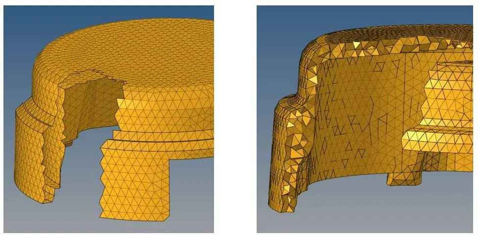
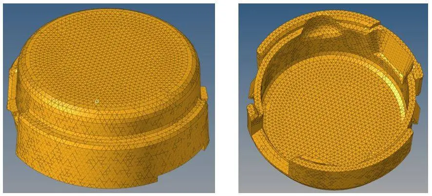
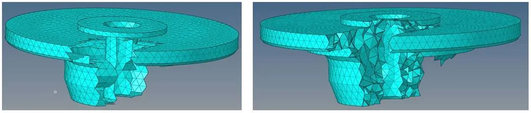
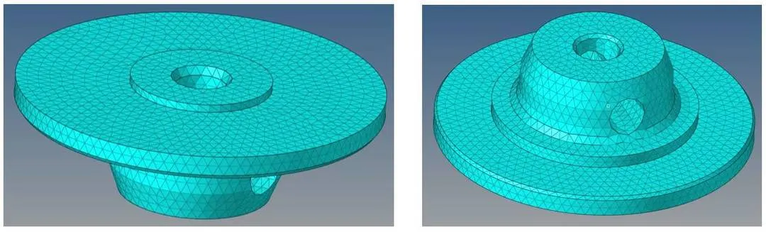
- 3D Hexa Meshing
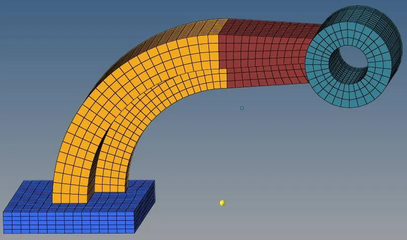
The objective of the project is to create a 3D hexa mesh of 10mm on the given model named arm bracket. 3D mesh can be generated using the various tools included in the 3D tool panel. Some commonly used tools for 3D hexa meshing are solid map, solid mesh, linear solid, spin, element offset and so on.
Step 1:
The arm bracket mesh model is generated from the base part. A 2d quad4 mesh is generated on one face of the base and element offset option is used to create the 3D hexa meshing. This can be done using solid layer option in the element offset tool, select the elements that needs to be offset, specify the surfaces along which the elements is to be generated, specify thickness of the part, input number of layers that needs to be generated and use offset option.
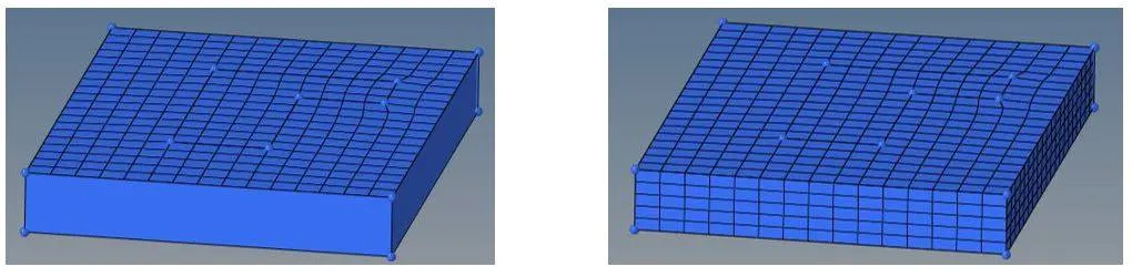
Step 2:
In the next step, the elements corresponding to the curved part is selected and spin tool was used to generate 3D elements along the part. Some parameters needed to be defined include angle of rotation, number of elements on spin, axis and centre of rotation.
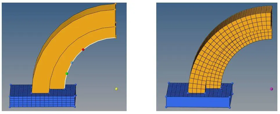
Step 3:
For the converging part in the body, one end of the part is meshed with same number of elements on the other and corresponding elements were referenced to each other using the linear solid option. This created 3D hexa elements along the part.
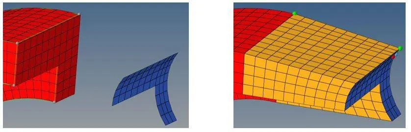
Step 4:
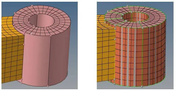
For the cylindrical part, one end of the part is meshed using 2D quad elements and 3D elements are created using solid map tool. In this option, the source and destination surfaces are selected and lines are selected to give the direction along which elements are generated.
Step 5:
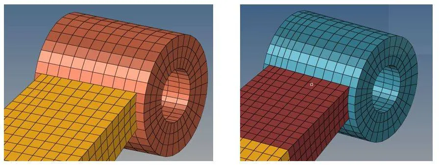
Its common to find connectivity errors between elements of adjacent parts. To achieve proper connectivity, edge equivalence option is used to create connections.
- 1D Elements
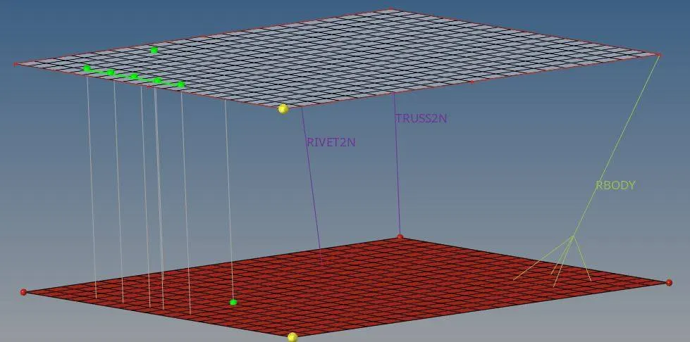
To create 1D meshing, the options in the 1D tool panel can be used. A prior requirement for creation of 1D elements is that nodes are required to generate these elements. Hence two surfaces with 2D mesh was created in the given model, such that the 1D elements are created in between these mesh surfaces. The creation of these elements are fairly straight forward. End nodes are selected and the type of element is selected depending on the geometry being solved. The degree of freedom of the elements can be controlled by checking the appropriate boxes given. Further, a cross section can also be generated depending on the geometry type using the Hyperbeam option. Some commonly used 1D elements include bars, rods, rigids, springs and so on. The below figure shows some of the 1D elements.
- Problems on Radioss
1. Check the material properties and calculate the speed of sound in steel rail =
l – Length of element
c – Speed of sound
E – Modulus
ρ - density
Ans: The material used is steel.
The unit system used is g/mm/ms.
Density, ρ = 0.0078 M kg/m3
Modulus, E = 210000 MPa
Speed of sound = c = sqrt(21000/0.0078) = 5188.74 m/s
2. The length of rail is 1000mm. Calculate the time taken for a shock wave to travel from one end of the rail to the other.
Ans: time taken by shock wave, t = l/c = 1/5188.74 = 0.000193 s = 0.193 ms
3. Ans: Time for sound to travel length of rail = 0.193ms
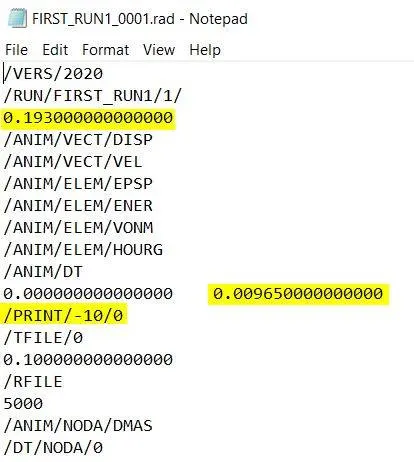
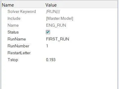
4. Edit the engine file so that the stress wave can be monitored, moving from one end of the rail to the other during the impact – this will require a termination time equal to the time it takes for the sound to travel the length of the rail (set on/RUN card)
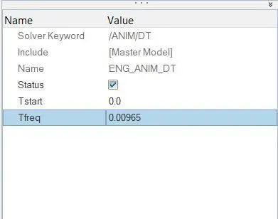
5. Set the frequency of the animation output to a time that will give 20 animation steps (/ANIM/DT)
Ans: Frequency = Tfreq = total time / number of steps = 0.193/20 = 0.00965
6. Change/print - 10