Assignment 11
OBJECTIVE:
1. Tutorial- single cyl DI add case 2 with discretization length 0.1 mm for intake runner and compare with default case 1
-
- Parameters-Torque, BSFC, max cylinder pressure
- simulation time
2. Explore tutorial no 2 (GEM3D) - “Building intake manifold from STL model” (80 marks)
METHODOLOGY:
Challenge 1
Tutorial- single cyl DI add case 2 with discretization length 0.1 mm for intake runner and compare with default case 1
-
- Parameters-Torque, BSFC, max cylinder pressure
- simulation time
CI engine Single Cylinder - 2 Valve Model
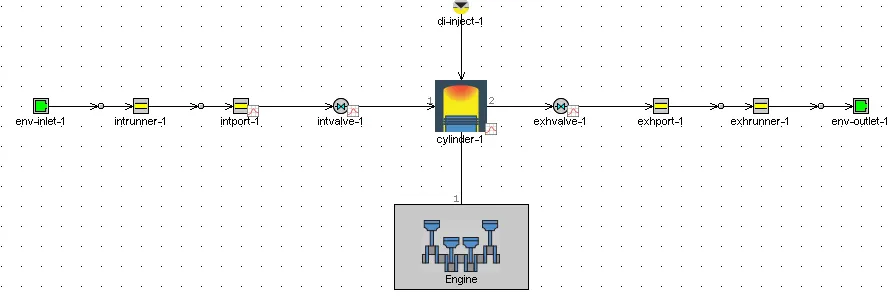
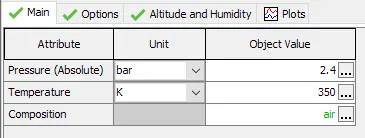
Environment Parameters:
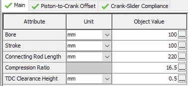
Cylinder Geometry:
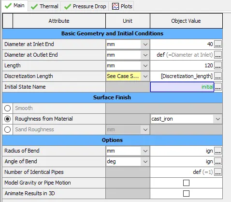
Intake Runner set Discretization Length as Variable:
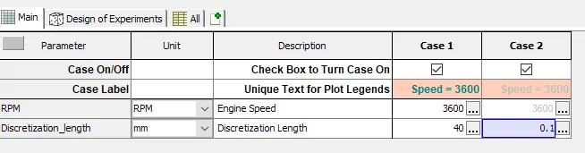
CASE SETUP
Speed = 3600 for both cases
Case 1= 40 mm discretization length
Case 2= 0.1 mm discretization length
RESULTS AND DISCUSSION
Engine Performance Parameters
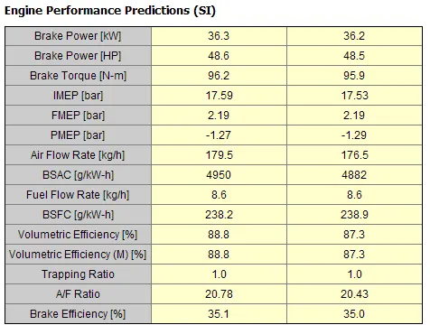
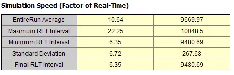
| Discretization Length | % difference w.r.t 40 mm | ||
| Parameters | 40 mm | 0.1 mm | |
| Torque (Nm) | 96.2 | 95.9 | -0.31% |
| BSFC (g/kW-h) | 238.2 | 238.9 | 0.29% |
| Maximum Pressure [bar] | 117.11 | 115.18 | -1.65% |
| Final RLT Interval | 6.35 | 9480.69 | 149202.20% |
Incylinder Pressure
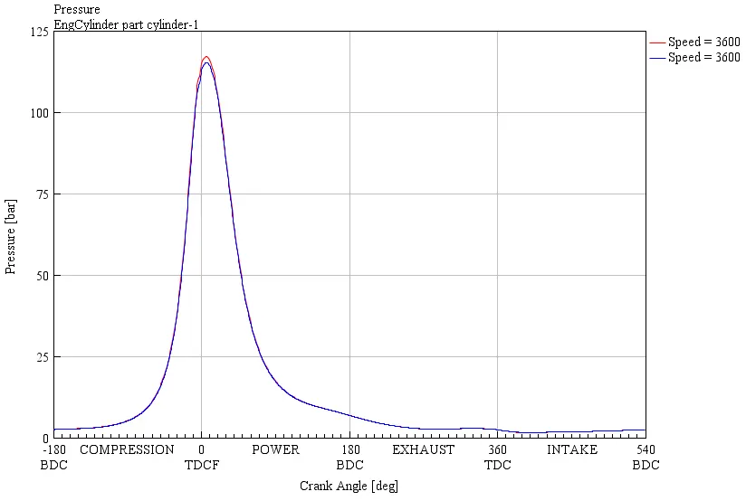
Inference: It is envisaged from the table that:
- 40mm discretization length has higher torque compared to 0.1mm discretization length
- 40mm discretization length has lower BSFC compared to 0.1mm discretization length
- 40mm discretization length has higher Maximum Pressure compared to 0.1mm discretization length
- RTL Interval simulation time for 0.1mm discretization length is 1493 times of 40mm discretization length
2. Explore tutorial no 2 (GEM3D) - “Building intake manifold from STL model”
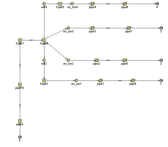
GEM-3D is used to convert the 3D geometry to 1D model.
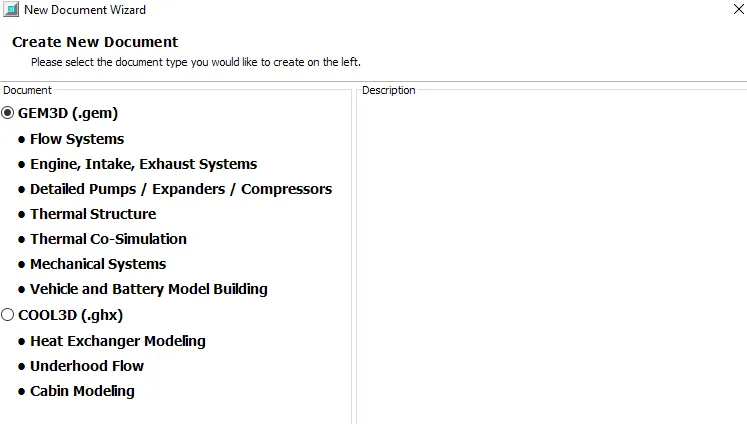
Step1: create a new model by selecting file ->new Document
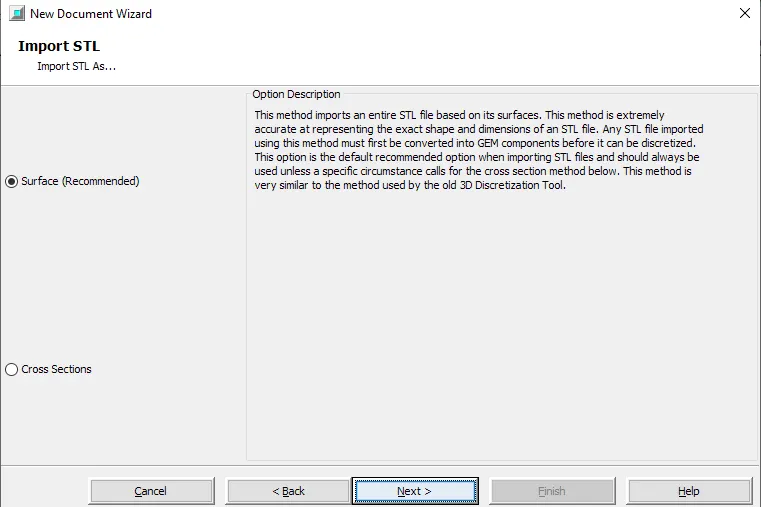
Step2: Import shell from an STL file and save the model
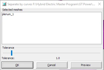
Step3: Separate Sections by Curve
Select the part and choose Separate By Curves from the Shape Operations group in the Convert tab. It will section the part in places where there is drastic change is cross section is appicable.
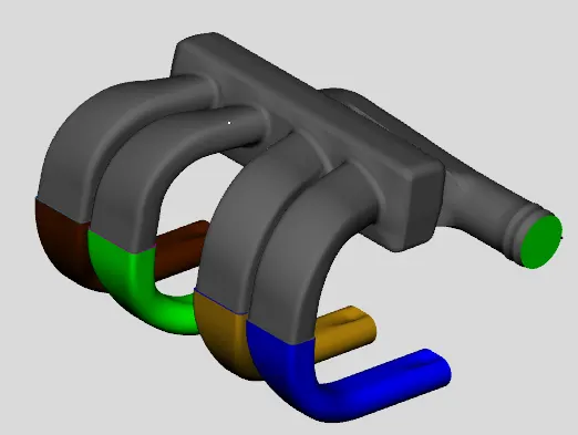
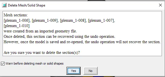
End sections of the runners and plenum are separated from the main shape, we can delete them from the model. To do this select the 5 end sections where there are exchange of air and delete them.
Step 4: Use the Cutting Plane
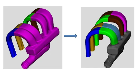
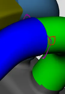
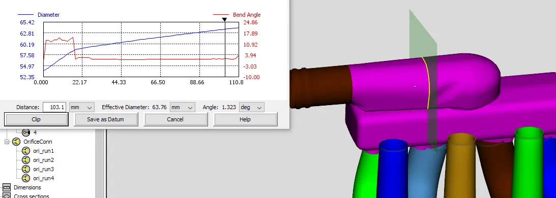
Separate the shapes into sections to represent as pipes and flow splits. Divide the runners using 3 Points Cutting Plane option. A cutting plane can then be created by clicking on 3 points on the model to define a plane.
Step5: Convert Sections to Flow Components
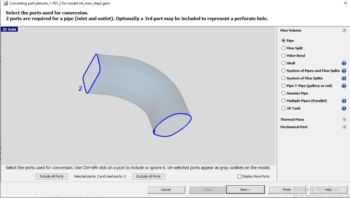
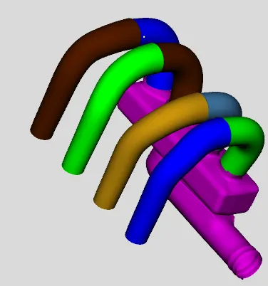
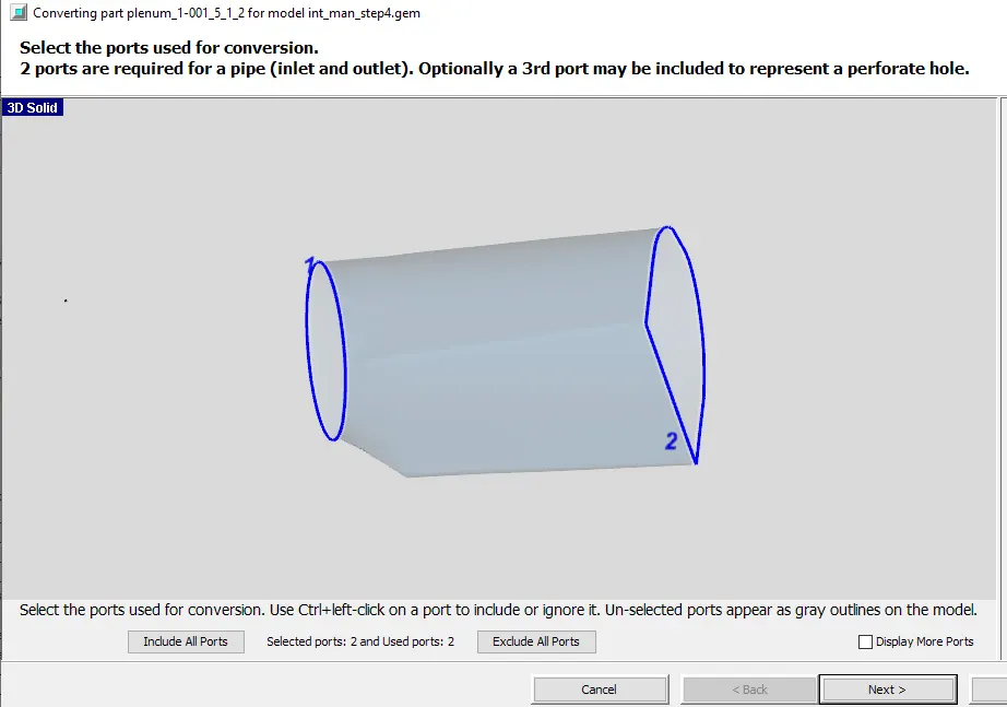
Convert all of the Runners to Flow components. Right-click on the first section of the first runner and select Convert Shape to Component. Select Pipe then Multiple Bends since it has more than 1 bend. Orientation is from planum to runner.
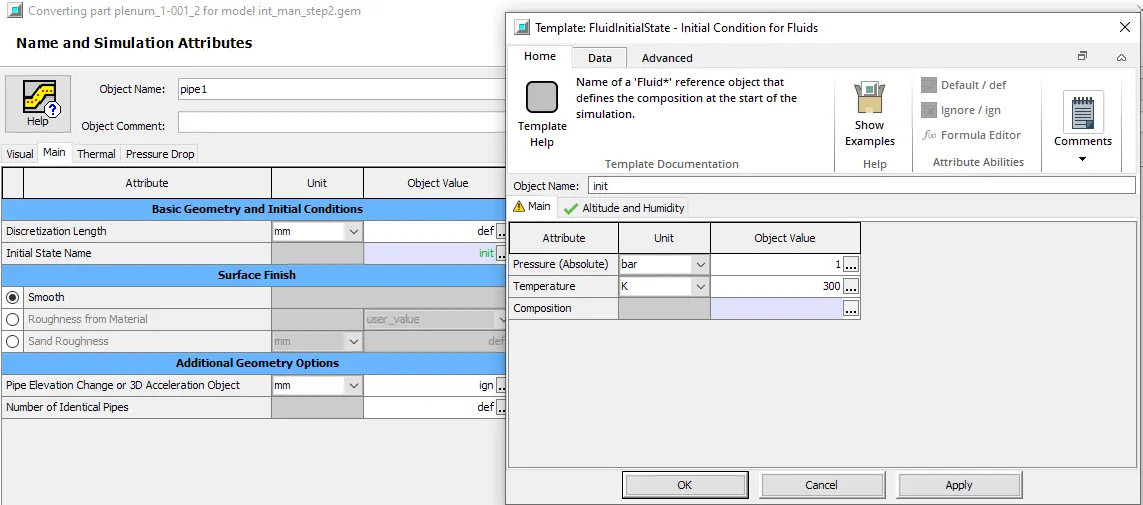
Then go to the main tab and type init for the Initial State Name. We can define the initial state directly in GEM3D by double-clicking on the name "init". This will open a 'FluidInitialState' template where we can define the Pressure as 1 bar and the Temperature as 300 K. We can get the properties of air from the template library by right-clicking in the cell for Composition and choosing value selector. In the value selector scroll down and choose the "air" 'FluidMixture' object.
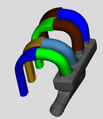
Repeat the same for remaining runners.
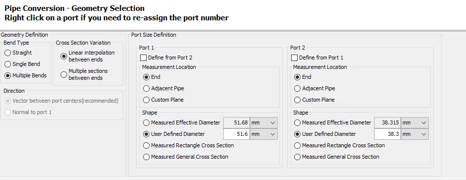
Delete the plane.
Step6: Add Custom Connection
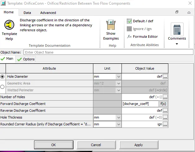
Step7: Set Value to Forward Discharge Coefficient - Parameter
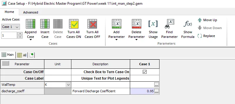
Repeat for all runners
Step8: Add Subassembly connection to Impose Connection Direction
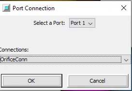
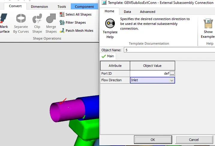
Make Port 2 of the runners as outlet for GT to understand. The ends of each runner need an end connection specified. This is done with a special subassembly connection. To add the subassembly connection right-click on the end section of the first runner component ("run1-2") and choose Add Connection.
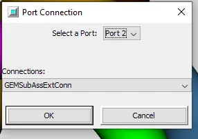
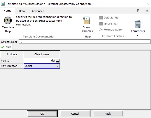
Repeat the same for the remaining runners.
Step9: Divide pipe section with Area Changes
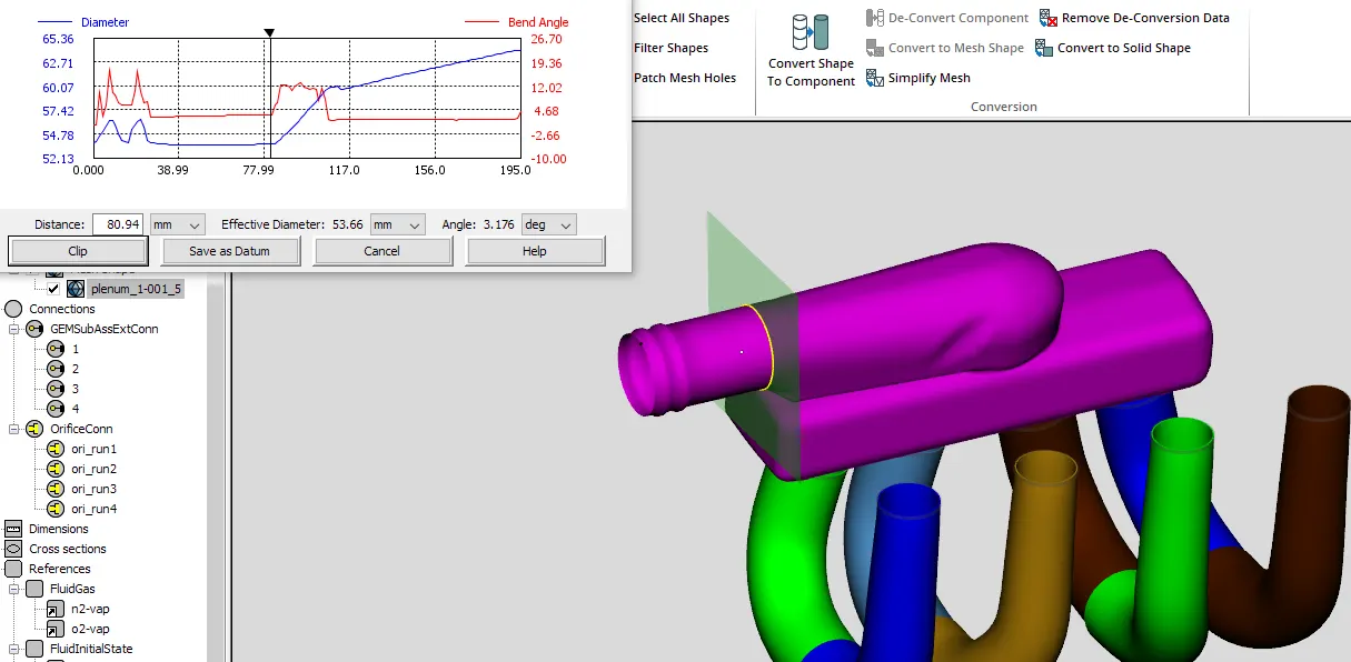
Step10: Making more Difficult Cuts
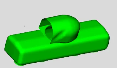
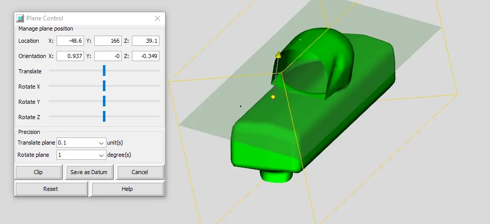
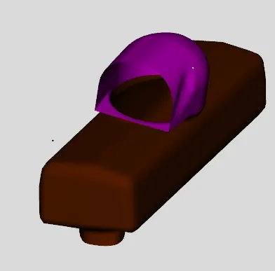
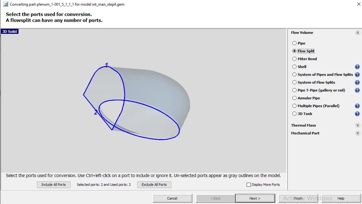
Step11: Determining Orientation During Conversion
Next convert the center section into a flowsplit. Right-click on it and select Convert Shape to Component. Select Flowsplit from the select the conversion geometry pane.
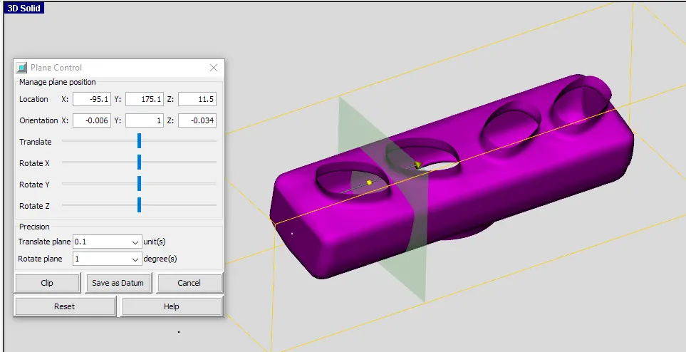
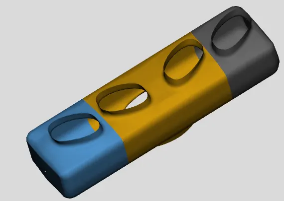
Step12: Flow Connections
The gaps between the pipe and plenum needs to be closed using extruded connections from connection option is taskbar. Select Flow Connection > Flow Connection from the Connections group under the tab Flow. This will show available surfaces for adding flow connections and repeat for extrude connections to close the gap.
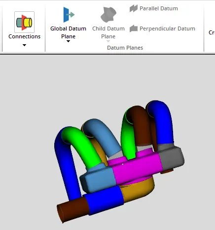
Step13: Discretize the Model
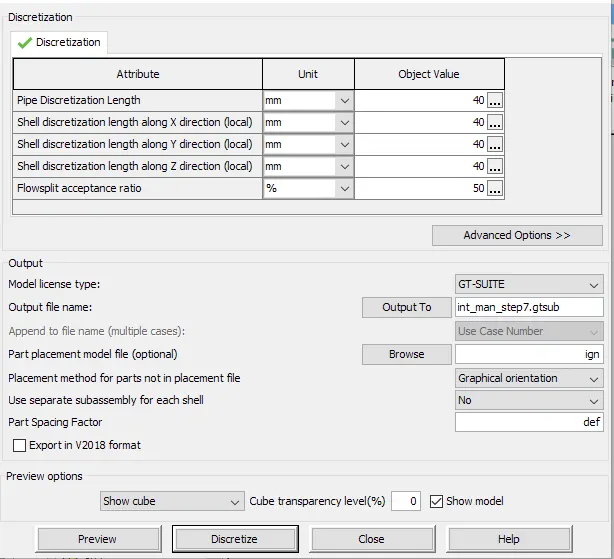
First orient the model and then click the Discretize button and GEM3D will create a GT-SUITE model file (.gtsub).