Assignment 1-2D Meshing Challenge
AIM :
To Preprocessing on the given three individual model according to the requirements which are pointed out. All such things should be done by using Hyper Mesh.
OBJECTIVES :
Geometry Cleanuping for each models.
Extracting the middle surface for each models.
Cleanup the middle surface and ignoring if there any hole which is less than 5 mm.
Create a Element Quality Criteria for shell meshing.
Create a shell elements on the middle surface based on requirements.
Assigning the proper thickness on it.
PROCEDURE FOR ATTAINING THE OBJECTIVES :
I) Geometry Cleanuping :
First of all, importing the models by separately which are given, then we have to cleanup the geometry if there could be an any issues are happened on it.
In Order to importing the model into the Hyper mesh, directly double click to open the model. Because, a file has been already saved by hypermesh format.
Make sure choose respective User profile based on what kind of analysis we going to do. In this case, we can select the any one either a Optistruct or Radioss. Because, As we just make a FE model alone irrespective of analysis.
In addition to that, make sure switch to "By Topo" mode instead of "Auto" mode. After that, we can able to visualize the geometry in the form of topological edges such as "Free Edges", "Sharped Edge", "T - Junction Edge" & "Suppressed Edge"
Part 1 :
In this model, there're lots of geometrical Issues has been presented in this model like few surfaces are missing & few surfaces are not sharded properly, by results free edges has been shown up like as in below image.
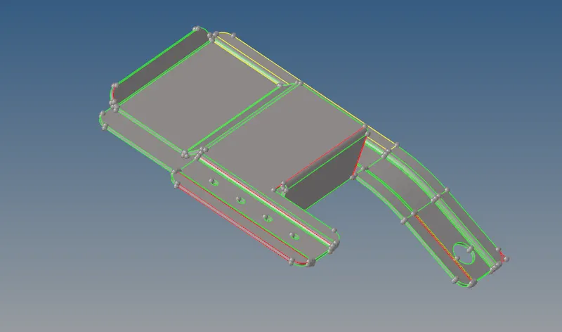
As we can clearly seen from below image, a free edges are created due to surfaces are not properly sharded or connected with each other.
In Order to get rid out of this error, we have to paste it together by using "Toggle" option which is available under "Quick Edit" option. Make sure we should have to provide the appropriate tolarance value by manually based on lateral distance between two free edges on where we gonna pasting together.
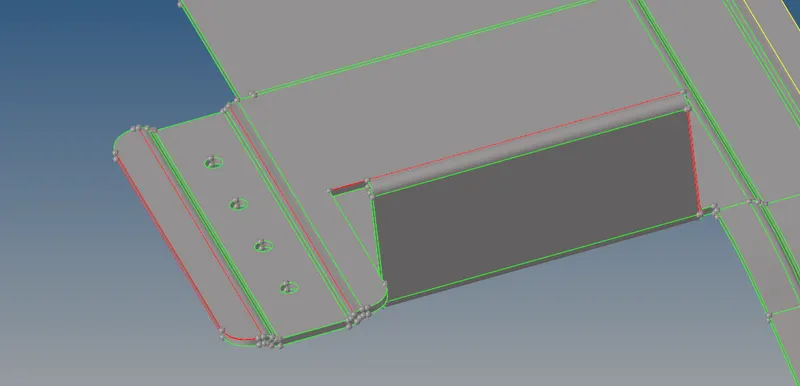
Here below image shown where surface is actually missing. We have to use the "Filler Surf" option to fill the hole which is available under the "Quick Edit" option.
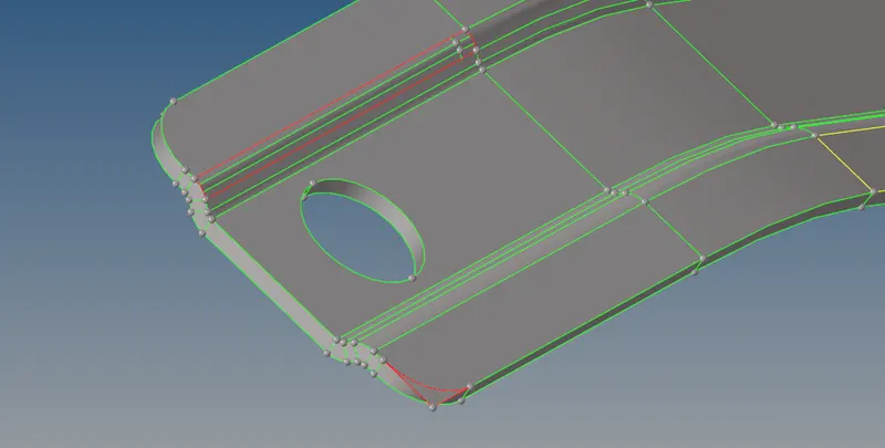
Once a model is completely cleanuped, it have been looks like as shown in below image.

After done the geometry cleanuping, we can go to next process which is extracting the middle surface from this above component.
Part 2 :
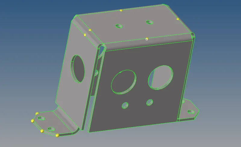
After As we inspected the part 2 model, there's no geometrical error hasn't been presented with that.
So, we can confidently go to next process which is extracting the middle surface for this model.
Part 3 :
Similarly like as model 2, there's no geometrical error hasn't been presented with this model itself.
So, we can confidently go to next process which is extracting the middle surface for this model.
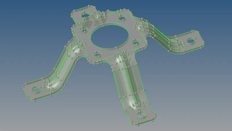
II) Extracting the middle surface :
A Middle surface is generated between at where neutral portion of the component. Mostly we can preferred, if thickness is constant at which throughout the component. It is used for reducing the computer calcuate time & reduce storage space as well.
We can able to extract the middle surface from the parent component by using automatic method as well as manual method.
First & foremost thing for automatic method, a component should be closed volume then we can able to extract the middle surface. A automatic method have consist of four different extraction method such as "Offset + planes+ sweep", "Offset + planes", "Offset" & "Skin Offset". If component have some features like fillets, have to prefer "Skin Offset" option as a extraction method for automatic middle surface extraction.
For manual method, make sure measure the appropriated thickness for that respective component. Select the "Offset" option which is way come under the "Surface Edit" option, there after select the top or bottom surfaces on the component along with make a duplicate on it. From that, provide the half a thickness of the respective component as a offset value. Make sure check the vector direction & then click the "Offset" option. These is how we can extract the middle surface by manually.
Use any one of the option which are available with us to extract the middle surface for all three component.
Once extract the middle surface from all three parent component, it will looks like as shown in below images.
i) Case 1:
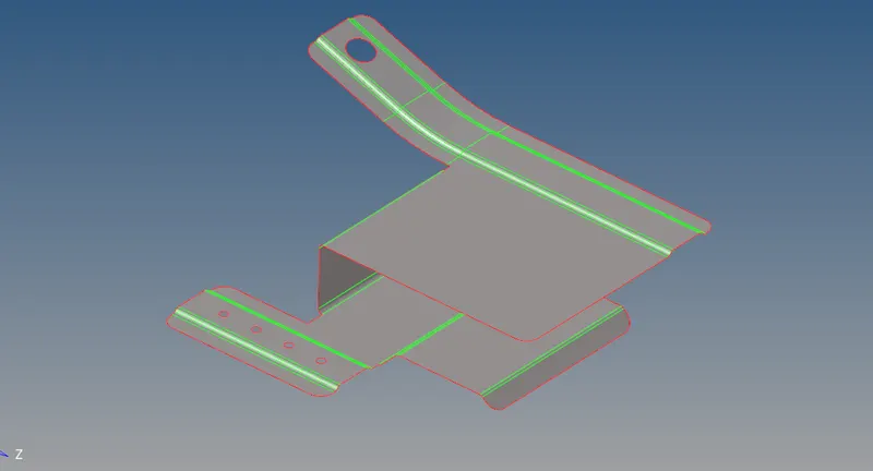
ii) Case 2 :
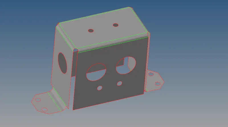
iii) Case 3 :
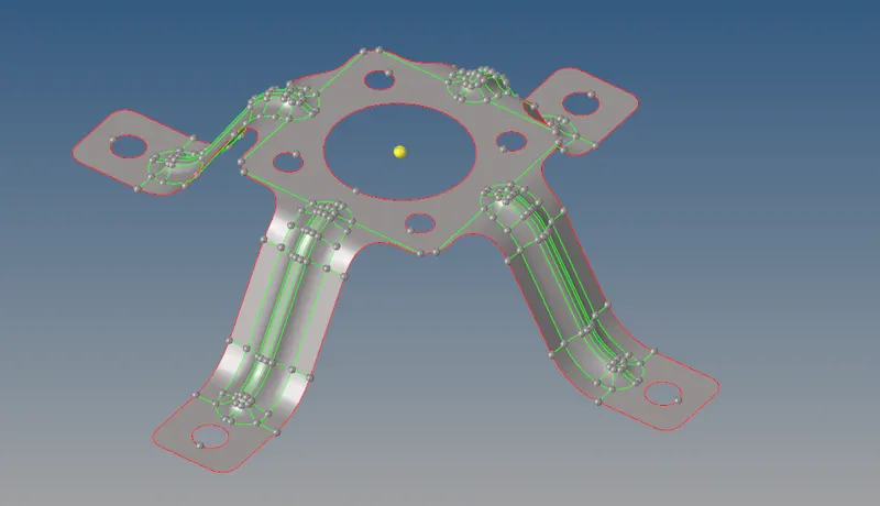
III) Cleanuping on the Middle surface :
Case 1 :
According to the element quality criteria, we have to keep only neccessary sharded edges where on feature locations. By using "Toggle option" to supress the excessive edges.
Addition to that, we should be ignore the holes which is less than 5 mm. By using "Filler Option " with able the suppress edges for fill the hole properly.
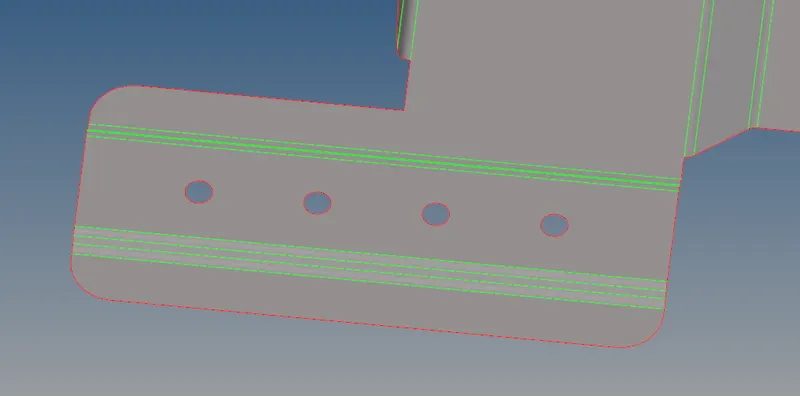
After suppressing the sharded edges & filling the hole, it has looks like as shown in below image.
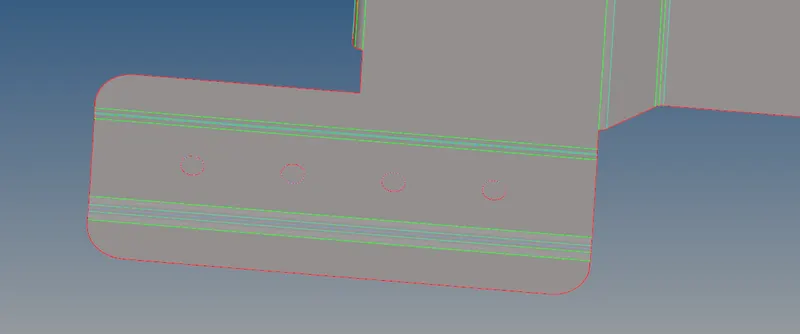
As we clearly see from below image, we have to keep the hole as it is, thenafter reworking on it for saving the elements due to element quality criterias.
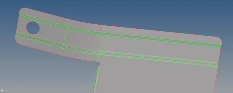
After reworking, it will looks like as shown in below image.
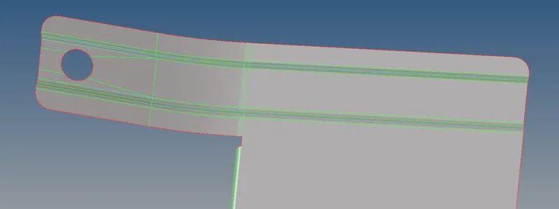
Case 2 :
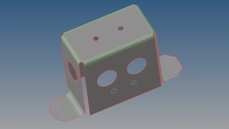
We have to remove the holes or fill the hole which is less than 5 mm by using filler option as shown in below image.
Case 3 :
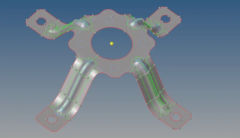
In this component, a lot of shared edges are presented which are cause to element failing.
We have to supress the shared edges like as shown in below. Moreover a component is looks exactly at symmetry in shape about an X & Y axis, by results we can easily able to copy & pasted the elements on opposite side without supressing the more number of edges.
And also, by using "filler hole" option to fill the hole like as shown in below image.
IV) Setting up the Element Quality Criterias :
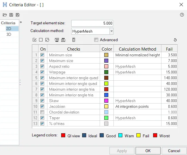
Whenever performing an shell meshing with mixed elements, we should always be consider such element quality criterias which are checkup in the Criteria Editor.
V) Meshing and Element Quality Checking:
It is a process of split the whole model into finite number of portions from infinite number of portion along with capturing all important features as much as possible, this framework is called meshing. This process is called Discretization.
In order to discretize the model, select the "Auto Mesh" option with set the element size which is 5 mm for in this cases.
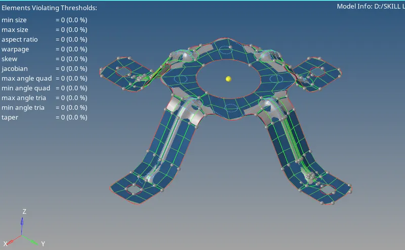
Select the face & click the "Mesh" option to generate the shell meshing on that face. Similarly, have to do on each & every surfaces where are available in the model and make sure have to check the element qualities which are passing or failing. If the elements are failing or mesh flow hasn't been attained in proper manner, have to be remeshing on it again & again until we get to rid out of this.
Similar process should be carrying out for all three models.
Case 1 :
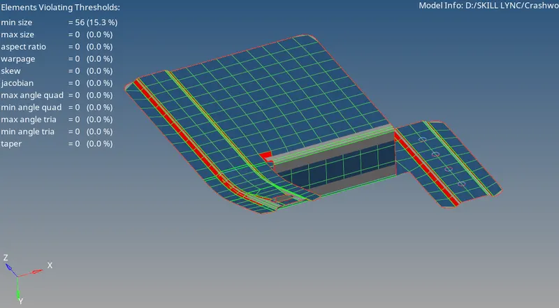
A few elements are failing due to minimum element length criterias which are generated on the fillet region & points located for proximity to each other.
If elements are failing for minimum element length, then computational time will slightly increased.
Case 2 :
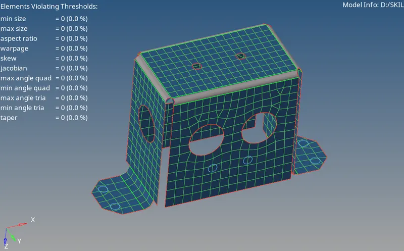
Case 3 :
VI) Assigning the thickness :
If the middle surface is extracted by automatic method, a property were created by hypermesh itself with appropriated thickness for that. In order to assign the property into the component, select the respective component & followingly click the property Id option & assign the corresponding property card.
Suppose, if we had extracted the middle surface by manual method, then we have to be create a new property id with provide the thickness by manually. Select the component & followingly click the property Id option & then assign the corresponding property card as same as in automatic method.
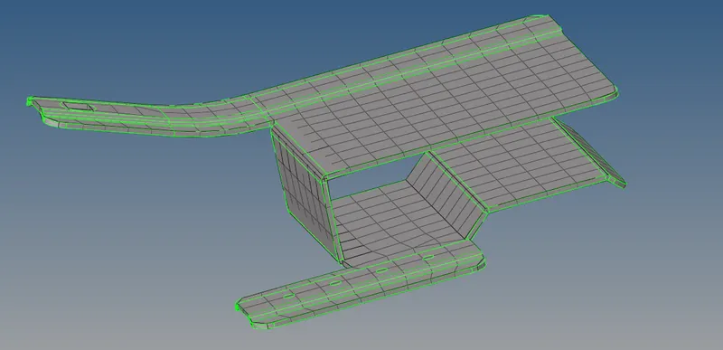
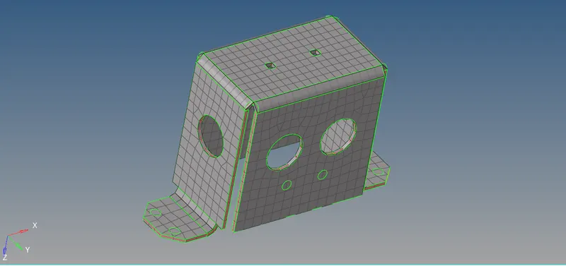
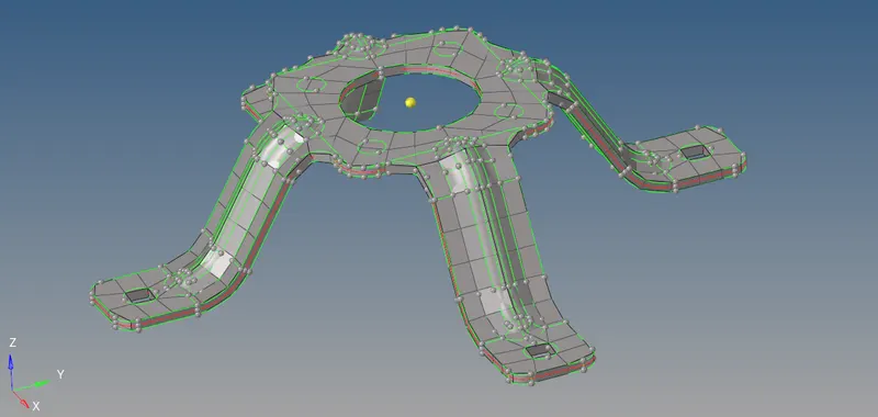
In order to visualize the thickness from the component, we have switch to "2D Detailed Element Representation" instead of "1D Traditional Element Representation". Once changed, we can able to see from the thickened component from graphical window for all three models like as shown in below images.
Case 1 :
Case 2:
Case 3:
CONCLUSION :
Successfully Preprocessing on the three component as per the requirements & procedure such as Geometry cleanup, Middle surface Extraction, Shell Meshing with mixed type of elements & then finally assign the thickness on it.