Assignment 1-2D Meshing Challenge
OBJECTIVE :
- To perform the geometry cleanup operation on the given files.
- To extract the midsurface of the model.
- To clean the midsurface of the model.
- To create 2D mesh with target length 5mm having minimum length 3.5mm and maximum length 7mm.
- To assign proper thickness to the mesh by creating a generic property.
CASE SET UP AND EXECUTION :
1. Practice model – The given model is as follows,
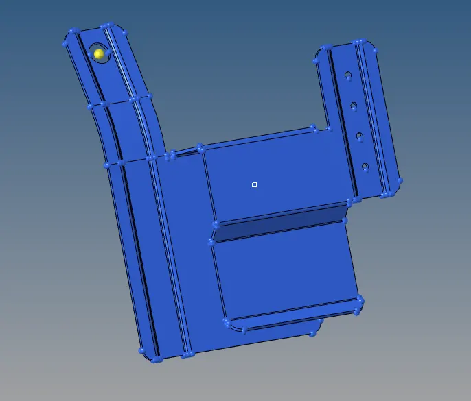
We will first import the model in Hypermesh using Import model browser option present in Tool Bar. After importing the model, we can see that there are some free edges and missing surfaces in the model. So we will perform the geometry clean up on the model. Geometry cleanup is performed on the model to obtain refine geometry which outputs better result in midsurfacing and therefore the meshing of the component. To perform the geometry cleanup we will navigate to quick edit panel by either pressing F11 shortcut key or through Geom page. In quick edit panel, we will use toggle edge option to toggle most of the free edge red lines to shared edge green line. We will also use filler surf to fill any missing surfaces and replace node option to replace and retain points to complete the geometry.
Then we will perform midsurfacing. To obtain the midsurface of the model, we will navigate to midsurface panel on Geom page. Here under extraction options, we will select offset+planes+sweeps, then we will select all the surfaces of the model in auto extraction sub panel and then we will click on extract command. Hypermesh will perform auto midsurfacing and we will obtain the midsurface of the model. Then we will again perform the geometry cleanup on the model to toggle the free edges and lines which may result in failure of element in minimum length criteria and to fill the holes having diameter less than 5 mm and various other operations using the same procedure of geometry cleanup mentioned above. Thus the geometry cleanup on the midsurface of the model is as shown below,
Geometry Cleanup and Midsurface result –
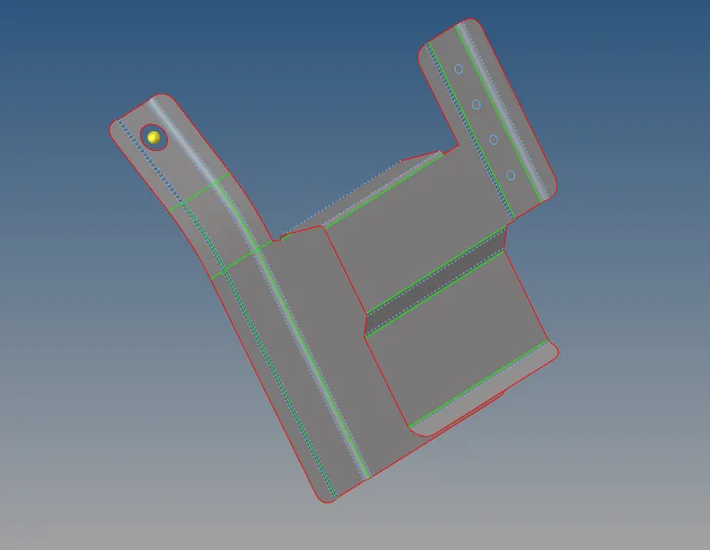
Now we can proceed for the 2D meshing of the model. Meshing is an integral part of the engineering simulation process where complex geometries are divided into simple elements that can be used as discrete local approximations of the larger domain. The mesh influences the accuracy, convergence and speed of the simulation. In general, 2D meshing is performed for objects having thickness less than 6 mm. To perform 2D meshing on the model, we will navigate to Automesh panel either by pressing F12 shortcut key or through 2D page. To mesh, we will select the surfaces one by one and create the mesh with target element size as 5 mm and mesh type as mixed. We will make sure that the holes are captured with even number of nodes and there are less trias generated in the mesh.
After completing the meshing of the model, we will check for quality criterias by pressing F10 shortcut key or check elems panel in Tool page. Here we will check for minimum length as 3.5 mm and maximum length as 7 mm criteria. If any elements are failing the quality criteria, we will optimize them by using cleanup tools and various commands such as combine, split, align, element optimize, smooth, project, replace node, etc. We will allow some elements to fail due to geometric restrictions.
Mesh Result –
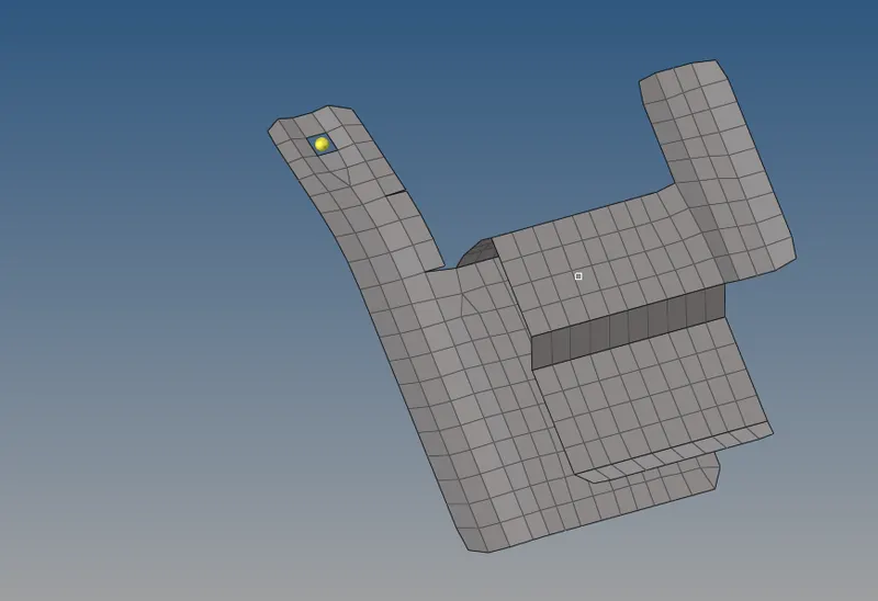
To assign thickness to the elements as per the parent geometry thickness, we will create a new property. Here, the model already contains a property; we will rename it as Thickness_0.91 as the thickness of the parent geometry is 0.91 mm. So we will enter 0.91 as thickness in Property Entity Editor window. Now we will assign this property to Midsurface component in Model Browser by right clicking on it and choosing the assign option. This will assign the thickness to the meshed elements. To view the thickened mesh, we will choose the 2D Detailed Element Representation in Tool bar.
RESULT and CONCLUSION –
Thus the Practice model is meshed with given element size and quality criterias.The thickness value is also assigned to the elements based on the thickness of parent geometry by creating a generic property. The final model is as follows,
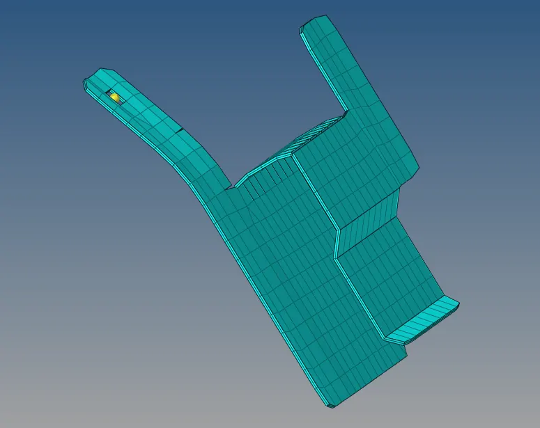
2. Clip Repair Model – The given model is as follows,
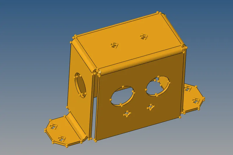
As discussed in the above model, we will import the model in Hypermesh using Import model browser option present in Tool Bar. In this model, there we no free edges or missing surfaces in the topology of the model. So we will not perform geometry cleanup on the model and will proceed for midsurfacing. To obtain the midsurface of the model, we will navigate to midsurface panel on Geom page. Here under extraction options, we will select skin offset, then we will select all the surfaces of the model in auto extraction sub panel and then we will click on extract command. Hypermesh will perform auto midsurfacing and we will obtain the midsurface of the model.
Now we will perform the geometry cleanup on the midsurfaced component. There are some points on the edges which can be retained to the point corresponding to the edge topology. This operation can be done with the help of replace point command in quick edit panel. We will also fill certain holes which may result in failure of element in quality criteria using filler surf command and then toggle the lines using toggle edge command to obtain plane surface. Thus the geometry cleanup on the midsurface of the model is as shown below,
Geometry Cleanup and Midsurface result –
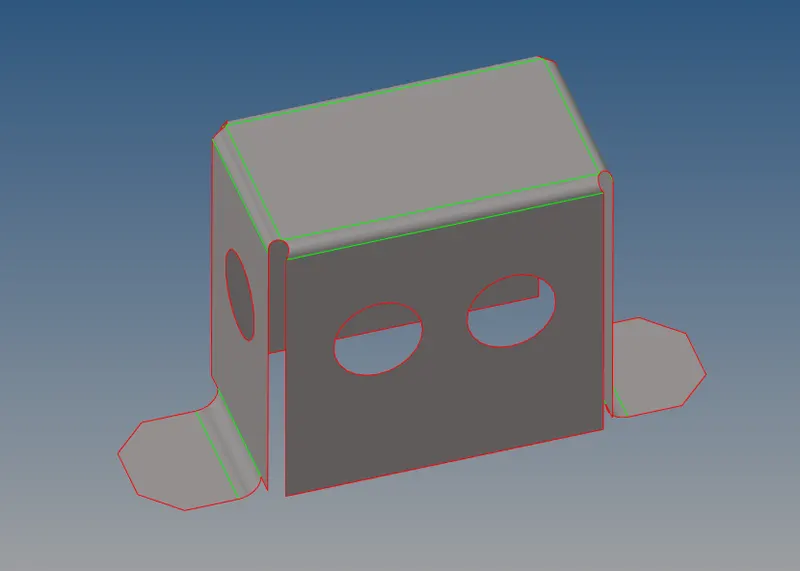
Now we can proceed for the 2D meshing of the model. As the midsurface geometry is symmetrical in x-axis and y-axis, we can create mesh on one symmetrical face and reflect it on the other symmetrical face. So, to perform 2D meshing on the model, we will navigate to Automesh panel either by pressing F12 shortcut key or through 2D page. To mesh, we will select the surfaces one by one and create the mesh with target element size as 5 mm and mesh type as mixed. We will make sure that the holes are captured with even number of nodes and there are less trias generated in the mesh.
To obtain better orientation of nodes present on holes, we will use rotate command to rotate the nodes. After meshing the surfaces, we will reflect the elements to x-axis and y-axis respectively using reflect command. Reflecting the elements will create element discontinuity of reflected elements to the original elements. So we will navigate to edges panel by using F3 shortcut key. Here we will equivalence the nodes of the elements which are reflected by using certain tolerance value. Following images represent the result of the model before and after reflect operation.
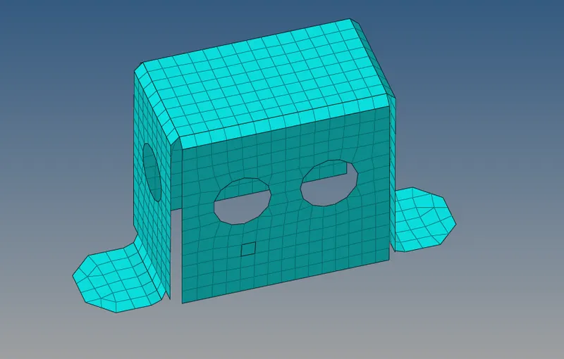
The reflected elements are checked for minimum length and maximum length criteria by pressing F10 shortcut key or check elems panel in Tool page. We will allow some elements to fail due to geometric restrictions. Here the reflected elements image shown above is also the meshing result of the model.
To assign thickness to the elements as per the parent geometry thickness, we will create a new property. Here, the model already contains a property; we will rename it as Thickness_2 as the thickness of the parent geometry is 2 mm. So we will enter 2 as thickness in Property Entity Editor window. Now we will assign this property to Midsurface component in Model Browser by right clicking on it and choosing the assign option. This will assign the thickness to the meshed elements. To view the thickened mesh, we will choose the 2D Detailed Element Representation in Tool bar.
RESULT and CONCLUSION –
Thus the Clip Repair model is meshed with given element size and quality criterias.The thickness value is also assigned to the elements based on the thickness of parent geometry by creating a generic property. The final model is as follows,
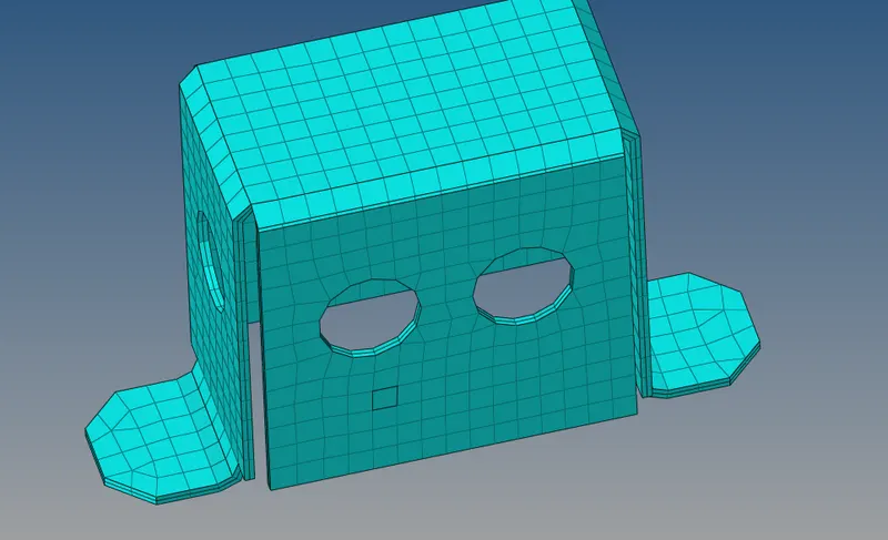
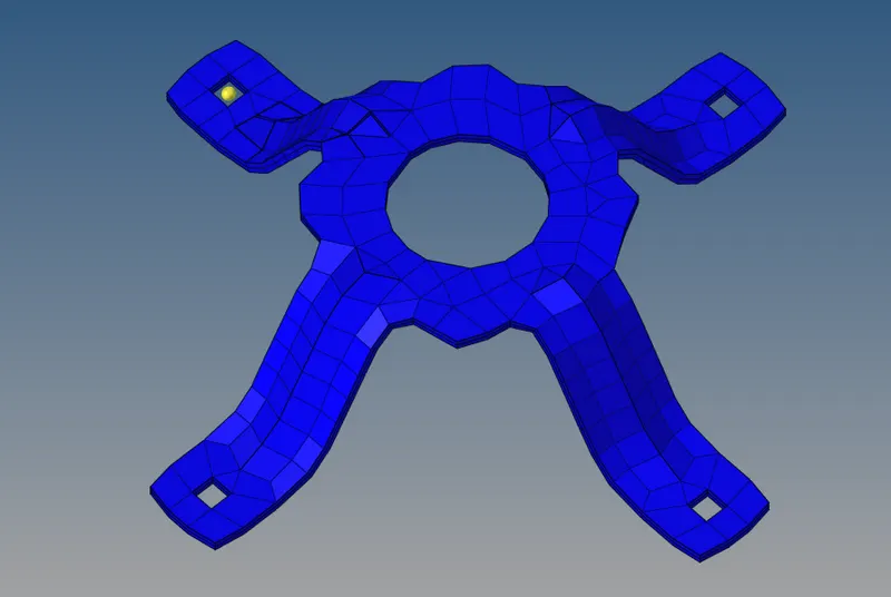
3. Mounting Bracket – The given model is as follows,
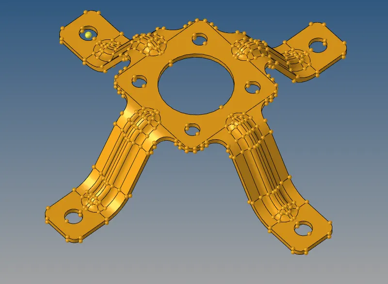
As discussed in the above model, we will import the model in Hypermesh using Import model browser option present in Tool Bar. In this model, there we no free edges or missing surfaces in the topology of the model. So we will not perform geometry cleanup on the model and will proceed for midsurfacing. To obtain the midsurface of the model, we will navigate to midsurface panel on Geom page. Here under extraction options, we will select skin offset, then we will select all the surfaces of the model in auto extraction sub panel and then we will click on extract command. Hypermesh will perform auto midsurfacing and we will obtain the midsurface of the model.
Now we will perform the geometry cleanup on the midsurfaced component. There are many green lines in some areas which may lead may result in failure of element in minimum length criteria. So we will toggle them using toggle edge command in quick edit panel. There are some holes which may also lead to failure of elements in quality, so we will fill these holes using filler surf command and then we will toggle them to obtain a plane surface. Thus the geometry cleanup on the midsurface of the model is as shown below,
Geometry Cleanup and Midsurface result –
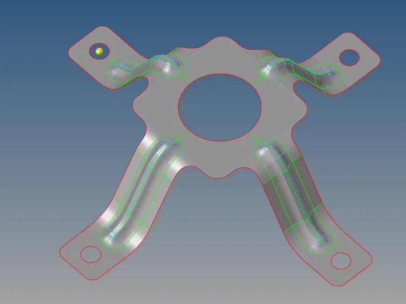
Now we can proceed for the 2D meshing of the model. As the model geometry is symmetry about z-axis, we can mesh one of the part and then rotate it three times to easily obtain the mesh. So, to perform 2D meshing on the model, we will navigate to Automesh panel either by pressing F12 shortcut key or through 2D page. To mesh, we will select the surfaces one by one and create the mesh with target element size as 5 mm and mesh type as mixed. We will make sure that the holes are captured with even number of nodes and there are less trias generated in the mesh.
Then we will navigate to rotate panel in Tool page. Here we will select the elements which we want to rotate and duplicate them. Then we will rotate them in z-axis at 90 degree using the center node as base node. We will again duplicate and rotate the displayed elements to 180 degree to obtain the entire mesh. Rotating the elements will create element discontinuity of rotated elements to the original elements. So we will navigate to edges panel by using F3 shortcut key. Here we will equivalence the nodes of the elements which are rotated by using certain tolerance value. Following images represent the result of the model before and after rotate operation.
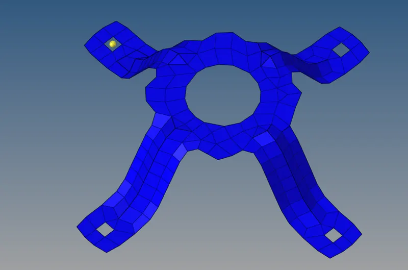
The rotated elements are checked for minimum length and maximum length criteria by pressing F10 shortcut key or check elems panel in Tool page. We will allow some elements to fail due to geometric restrictions. Here the rotated elements image shown above is also the meshing result of the model.
To assign thickness to the elements as per the parent geometry thickness, we will create a new property. Here, the model already contains a property; we will rename it as Thickness_1.8 as the thickness of the parent geometry is 1.8 mm. So we will enter 1.8 as thickness in Property Entity Editor window. Now we will assign this property to Midsurface component in Model Browser by right clicking on it and choosing the assign option. This will assign the thickness to the meshed elements. To view the thickened mesh, we will choose the 2D Detailed Element Representation in Tool bar.
RESULT and CONCLUSION –
Thus the Mounting Bracket model is meshed with given element size and quality criterias. The thickness value is also assigned to the elements based on the thickness of parent geometry by creating a generic property. The final model is as follows,