Assignment 1-2D Meshing Challenge
2D meshing challenge
Aim: To perform a 2D meshing of three given parts according to the quality criteria considered and assign a thickness property for the parts.
Quality criteria
Minimum elements:3.5mm.
Maximum elements: 7mm.
Target element size: 5mm.
Model-1
Step 1
Impost the model and check for errors in the model
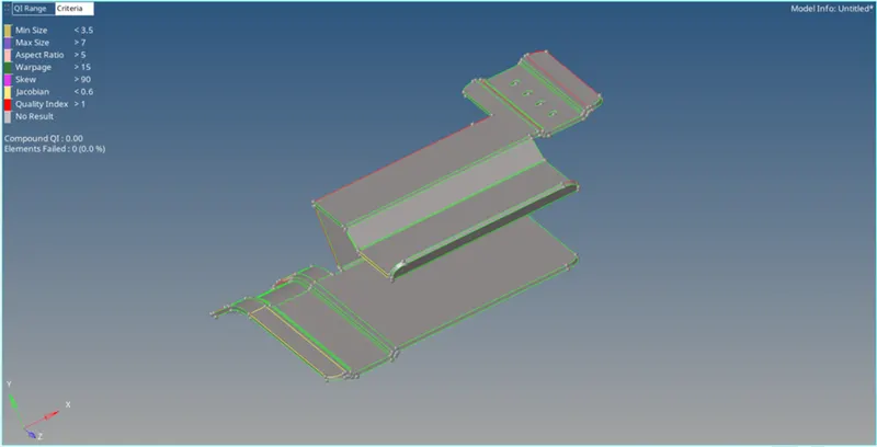
Model with errors (red and yellow lines)
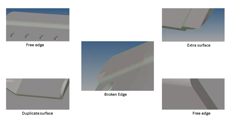
The following errors were detected: Free edges; Duplicate surfaces; Missing surfaces. These errors were fixed with the Quick edit option in the geometry panel. The option used are Toggle edge; add/remove points; Filler surf; Delete surface; trim with surface/place (surface edit) .
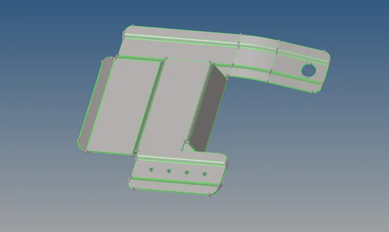
Fully cleaned geometry
Step 2:
The cleaned model is now ready for mid-surface extraction. The thickness of the model is measured using the Distance option. Once the thickness is known the mid-surface can be extracted using offset option in the surface edit panel or using auto mid-surface option in the geometry panel. In this method the auto mid-surface with skin offset option is used.
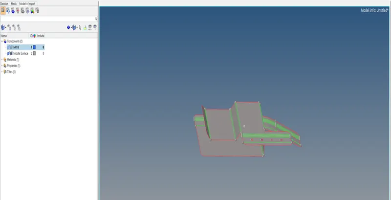
Mid-surface of the model
Step 3:
Since diameter less than 5mm is ignored, some of the holes are filled using filler surface and toggle edge. Similarly, the ruled meshing option can be used to fill the hole which is not necessary for the analysis.
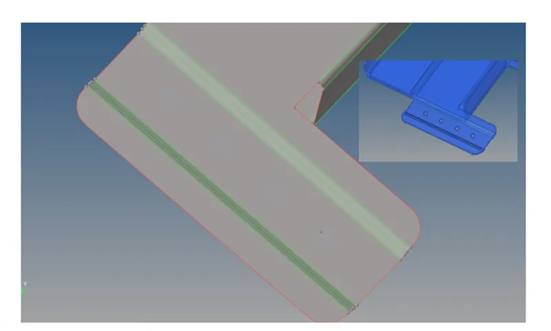
Holes less than 5mm diameter filled
Step 4:
Once the required clean up is completed, the model is meshed using Auto mesh option with the quality criteria in 2D panel.
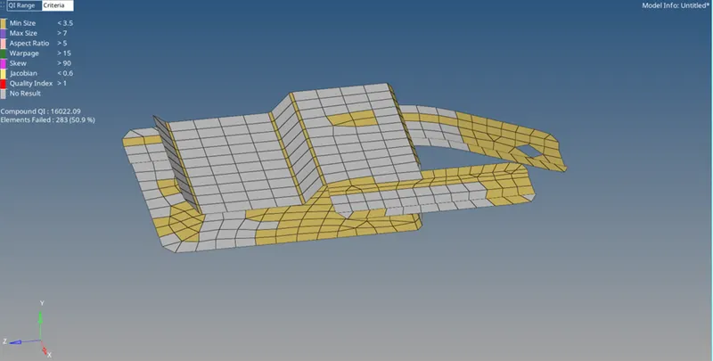
Initial mesh based on quality criteria
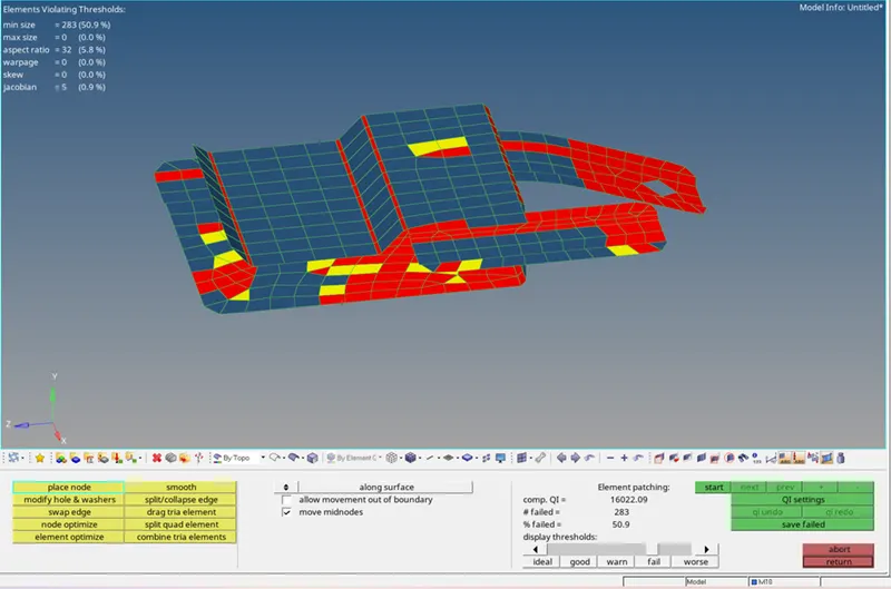
Initial mesh based on quality index
The mesh is checked for quality criteria and quality index and the required clean up is carried out with options like element cleanup; element optimize; drag tria elements; place nodes and smooth.
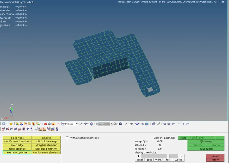
Final cleaned mesh
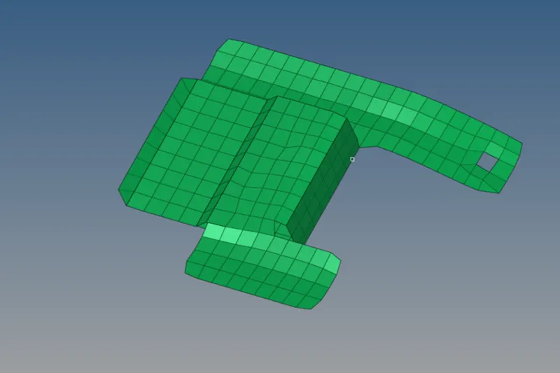
Meshed model
Step5:
Once the mesh is cleaned up. The 2D meshed element is assigned with a property as shown below
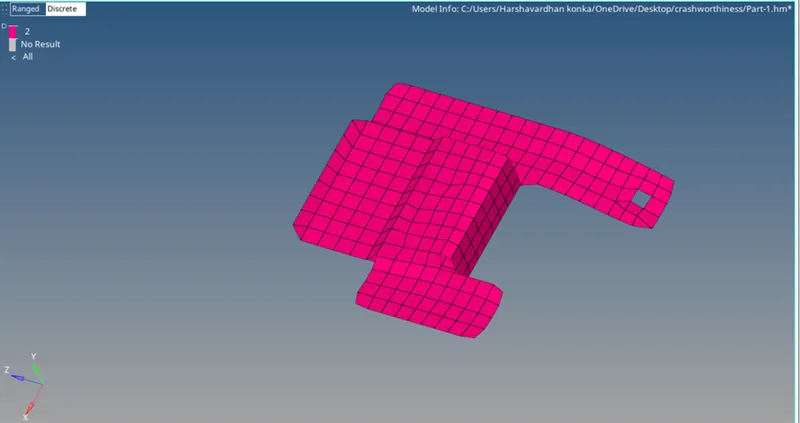
Model with thickness
Part – 2
The Part -2 to be meshed is given below. The procedure for part-1 is followed for the meshing process.
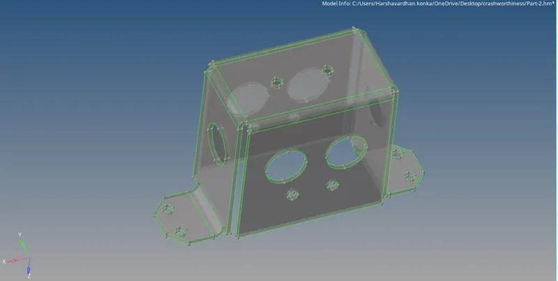
Model for Meshing
Since the model is has a symmetry design, one half of the model is split using Organize panel
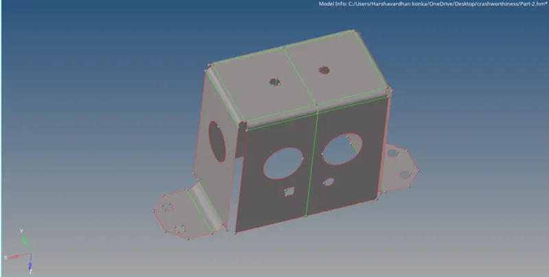
Splitted Model
Model is splitted using the Split surface option in the geomentry panel
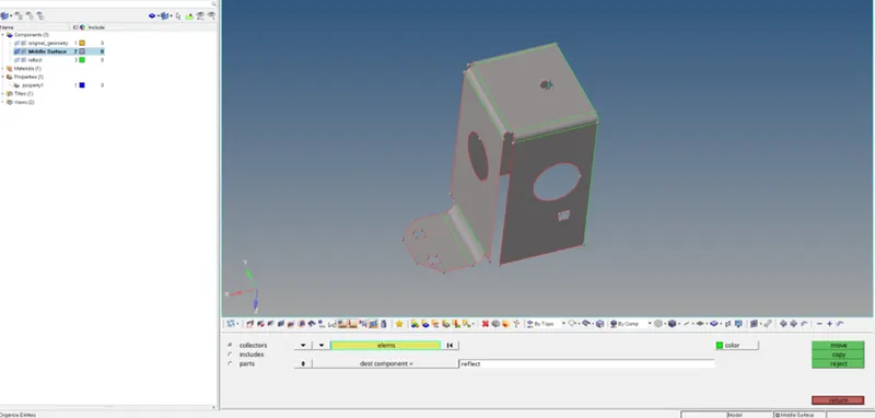
Model organised into Reflect component
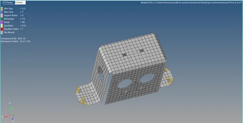
Final meshed model with Element quality
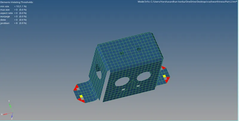
Quality index of the meshed model
The meshing is followed as described in part 1. The mesh leads to failing of elements at the corner, which has developed since the target element size is forced to maintain.
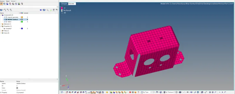
Model with the assigned property thickness
Part-3
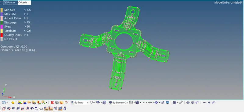
Model for Meshing
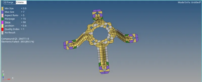
Initial mesh with element quality
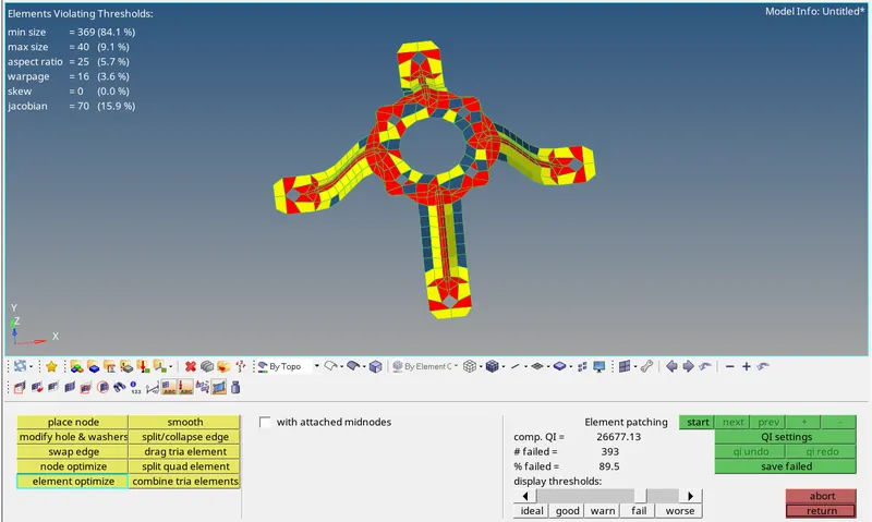
Initial mesh with quality index
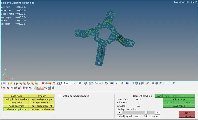
Final Meshed model
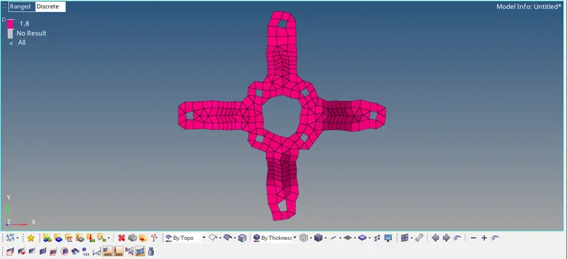
Model with the assigned property of thickness