Assignment 1-2D Meshing Challenge
AIM
Carry out the geometry cleanup operation on the given 3 files.
- Practice
- Clip Repair
- Mounting Bracket
There should not be any free edges, convert all of them into refine geometry.
- Clean the geometry.
- Extract midsurface.
- Clean midsurface geometry.
- Ignore holes less than dia 5mm.
- Create 2D mesh with target length 5mm, min 3.5mm max 7mm.
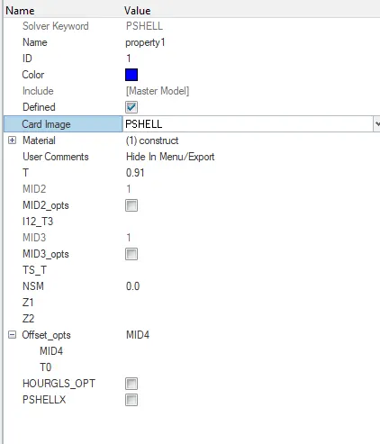
- And assign proper thickness, by creating a generic property.
- Then Save in .hm format.
Solution 1:
1. First step is openig our cad geometry in hypermesh. Geometry imported in Hypermesh is shown below. Geometry consists of one parts.
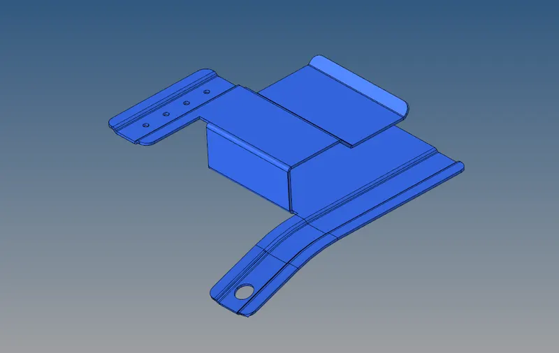
- After that topology vsualization has been done to known about the geometrical errors .
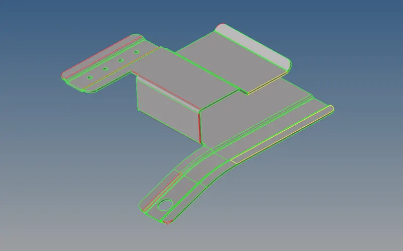
We can see that it consists of error which can be cleaned by using geometryceanup option present in the hypermesh.
- This can be edited with the help of quick edit tool present in Geometry submenu option.

- We can use filler surface present in the option to fill the open surfaces present on the surface.
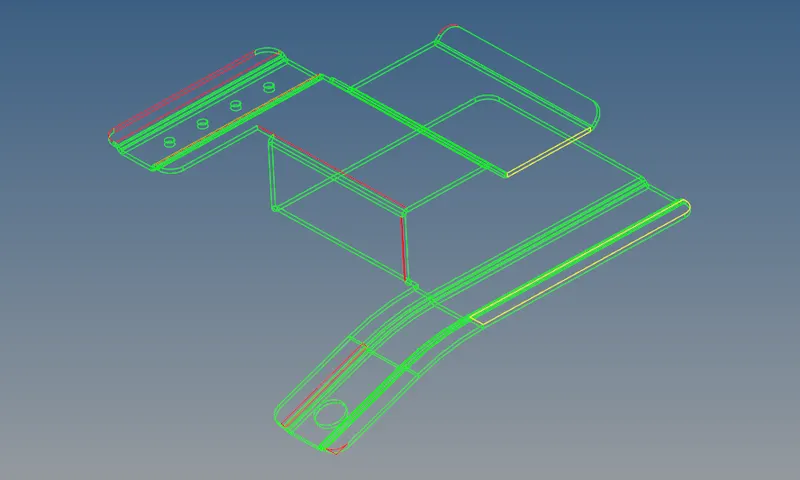
- After selecting the filler surface option , we can select the the closed loop surface to fill it.
- We can use the edit edge option to replace the edges in the model.

- After geometry cleanup next step is midsurface generation.
- Midsurface panel to extract the midsurface representation of a solid part or to generate a finite element shell representation of a solid geometry.
- For the Mid Surface of the, auto mid surfacing is performed.
- In Geometry Tab, Select Mid surface >> Select Surfs option >> Select the Surface >> Click Extract.
- The Mid surface is created.

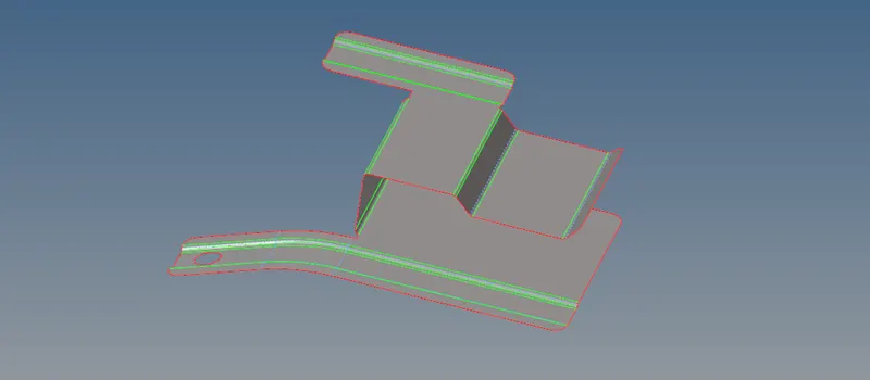
After that mesh criteria frile is changed according to requirement.
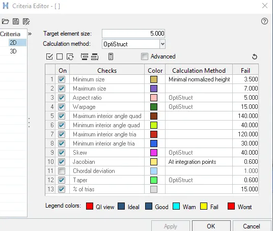
- After that 2D tetramesh is generated .
- Meshing is an integral part of the engineering simulation process where complex geometries are divided into simple elements that can be used as discrete local approximations of the larger domain. The mesh influences the accuracy, convergence and speed of the simulation.
- 2D Meshing option is shpwn below:

- After meshing, elements is checked forbad quality elements .
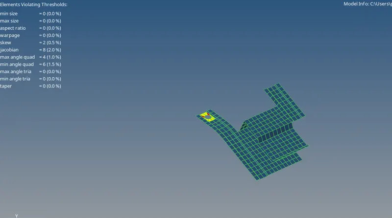
- Bad quality elements has been removed by the cleanup tools.
- Below image shows the Cleanup tool available to optimizeor correct the mesh.

After meshing and elements cleanup surface is shown below.
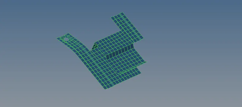
After that thickness has been provide with property card definition for the components.
PART : 2
- First step is openig our cad geometry in hypermesh. Geometry imported in Hypermesh is shown below. Geometry consists of one parts.
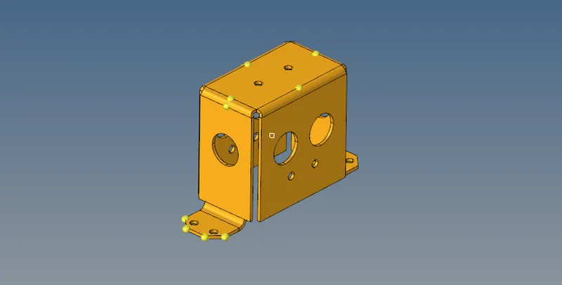
- After that topology vsualization has been done to known about the geometrical errors .
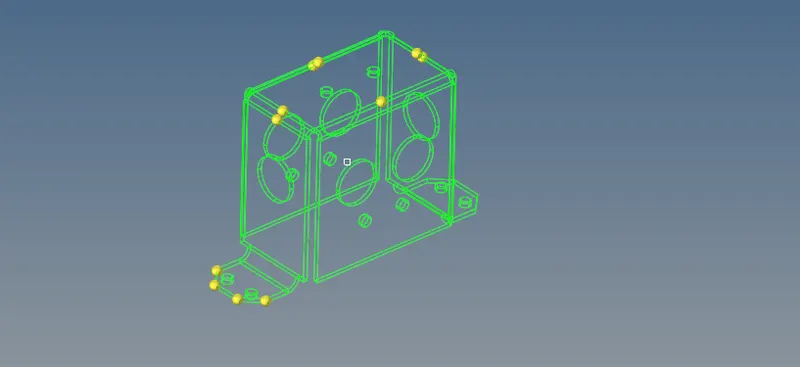
As there is no geometrical error found , we move on to next step midsurface generation
- After geometry cleanup next step is midsurface generation.
- Midsurface panel to extract the midsurface representation of a solid part or to generate a finite element shell representation of a solid geometry.
- For the Mid Surface of the, auto mid surfacing is performed.
- In Geometry Tab, Select Mid surface >> Select Surfs option >> Select the Surface >> Click Extract.
- The Mid surface is created.
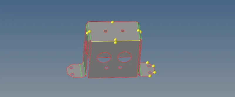
After that mesh criteria frile is changed according to requirement.
- After that 2D tetramesh is generated .
- Meshing is an integral part of the engineering simulation process where complex geometries are divided into simple elements that can be used as discrete local approximations of the larger domain. The mesh influences the accuracy, convergence and speed of the simulation.
- 2D Meshing option is shpwn below:
- Mesh Generated is shown below.
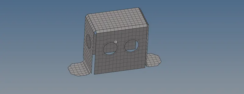
- After meshing, elements is checked forbad quality elements .

- Bad quality elements has been removed by the cleanup tools.
- Below image shows the Cleanup tool available to optimizeor correct the mesh.
After meshing and elements cleanup surface is shown below.
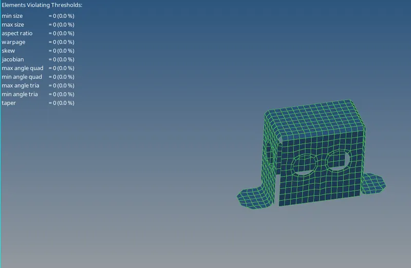
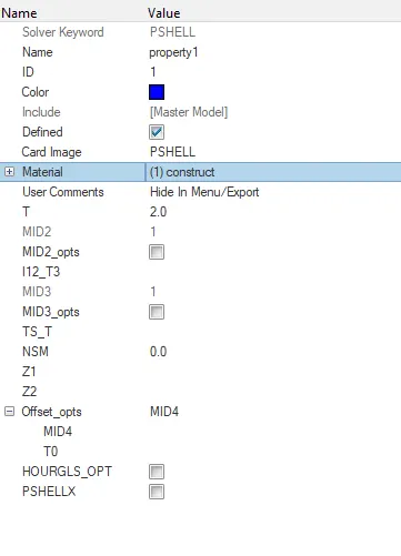
After that thickness has been provide with property card definition for the components.
==================================================================
PART -3
1. First step is openig our cad geometry in hypermesh. Geometry imported in Hypermesh is shown below. Geometry consists of one parts.
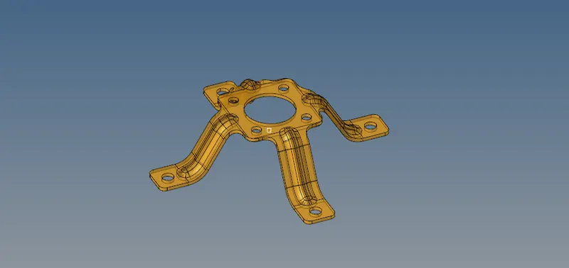
- After that topology vsualization has been done to known about the geometrical errors .
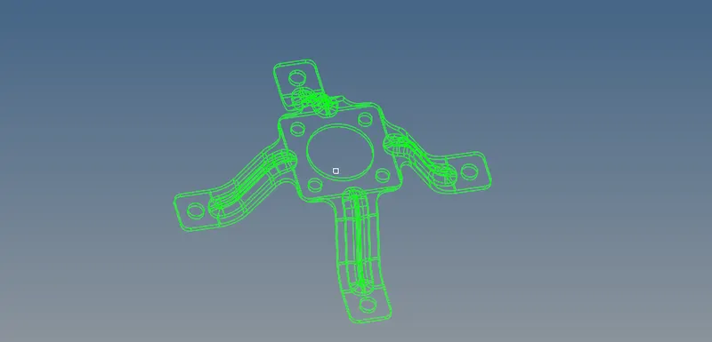
As there is no geometrical error, next step is midsurface generation.
- After geometry cleanup next step is midsurface generation.
- Midsurface panel to extract the midsurface representation of a solid part or to generate a finite element shell representation of a solid geometry.
- For the Mid Surface of the, auto mid surfacing is performed.
- In Geometry Tab, Select Mid surface >> Select Surfs option >> Select the Surface >> Click Extract.
- The Mid surface is created.
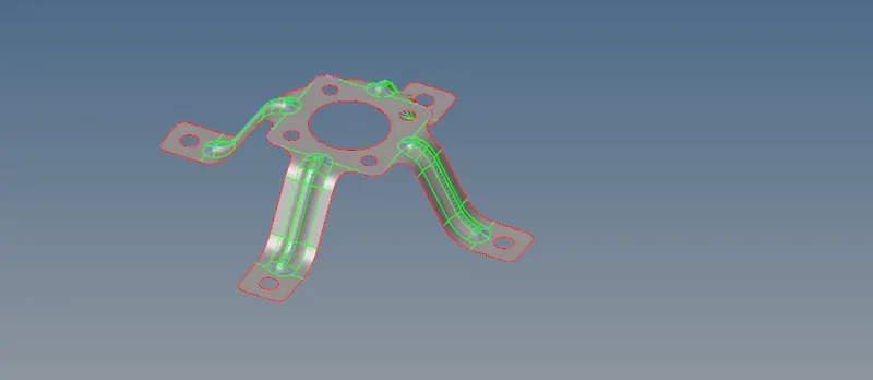
After that mesh criteria frile is changed according to requirement.
- After that 2D tetramesh is generated .
- Meshing is an integral part of the engineering simulation process where complex geometries are divided into simple elements that can be used as discrete local approximations of the larger domain. The mesh influences the accuracy, convergence and speed of the simulation.
- 2D Meshing option is shpwn below:
- Mesh generated is shown below.
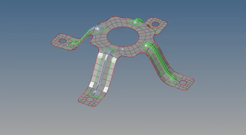
- After meshing, elements is checked forbad quality elements .

- Bad quality elements has been removed by the cleanup tools.
- Below image shows the Cleanup tool available to optimizeor correct the mesh.
After meshing and elements cleanup surface is shown below.
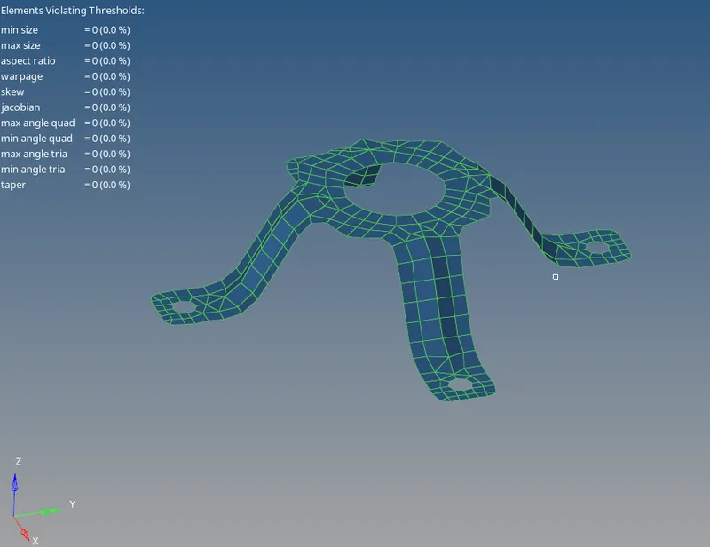
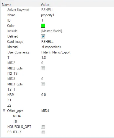
After that thickness has been provide with property card definition for the components.
======================================================================================
Conclusion
- The given challenge has been successfully performed.
- Midsurface generation , and meshing of all three components has been successfully created.