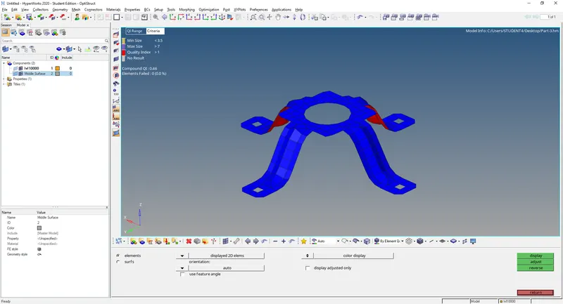
Assignment 1
Part 1
Switching to mixed topology view to find what all needs to be fixed while geometry cleanup.
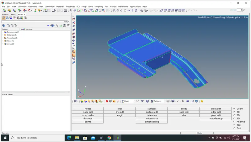
Zooming to the right side of the model shown above, a missing face & unwanted face was observed.
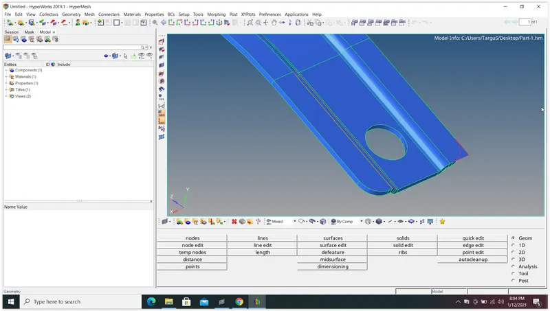
Fixing the missing face using filler surface option under quick edit & splitting the unwanted face using trim with surface option under surface edit and then deleting it.
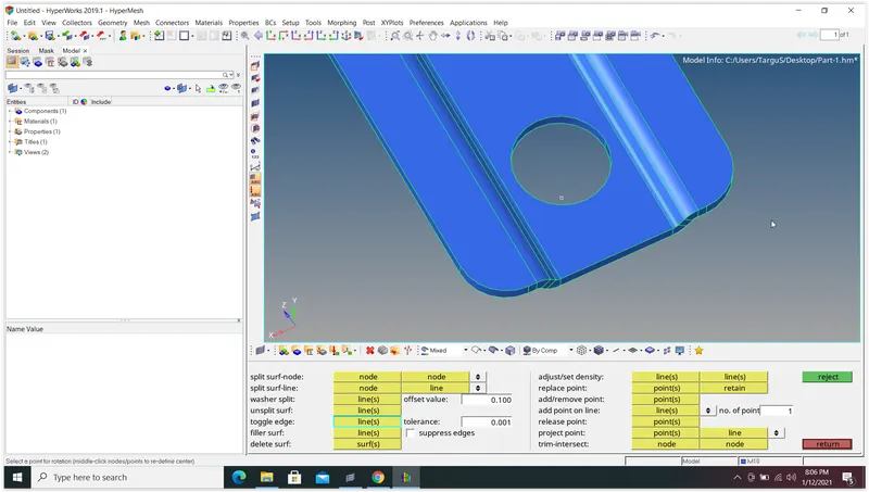
Cleaning the rest of the geometry using similar operations.
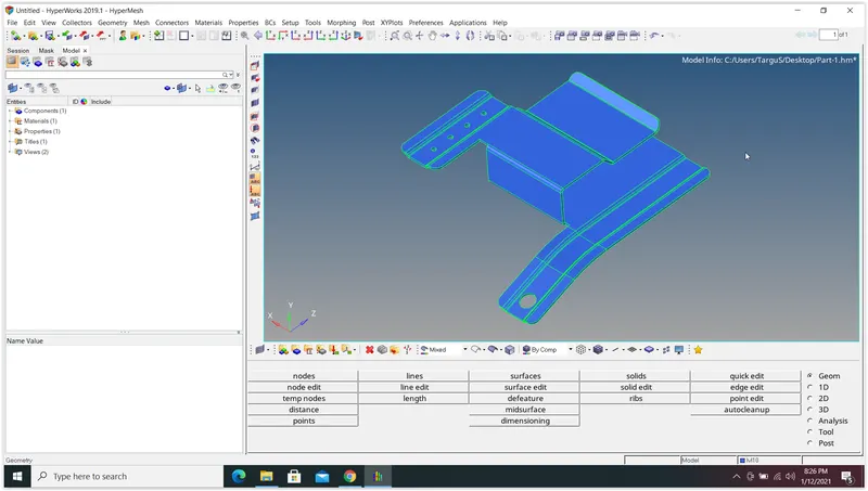
Using the auto midsurface extraction function to obtain the midsurface of the model.
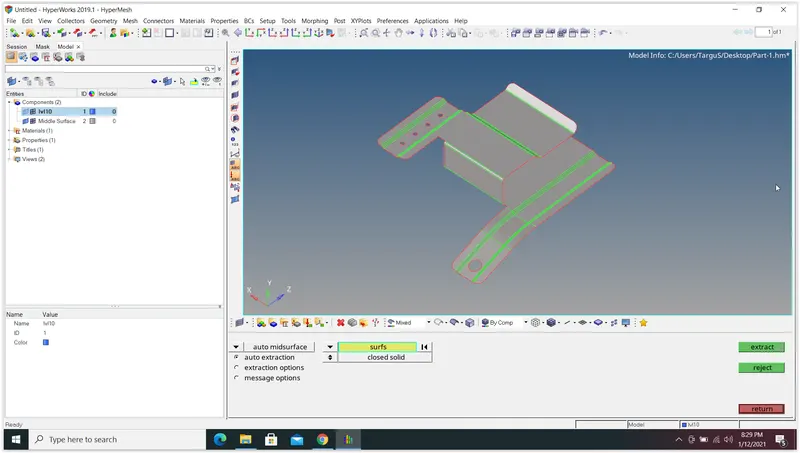
Removing all holes under 5mm diameter using pinhole function under defeature option.
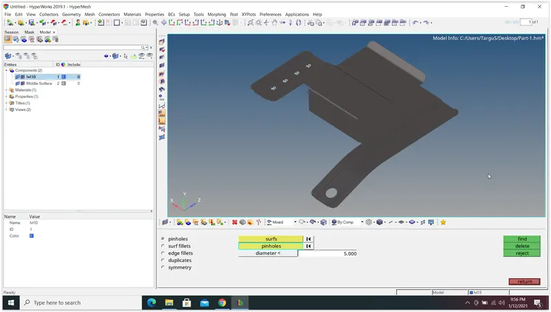
Similarly, defeaturing all small radius fillets so that after meshing the given element quality criteria are not violated. For this surface fillet function inside defeature option is used.
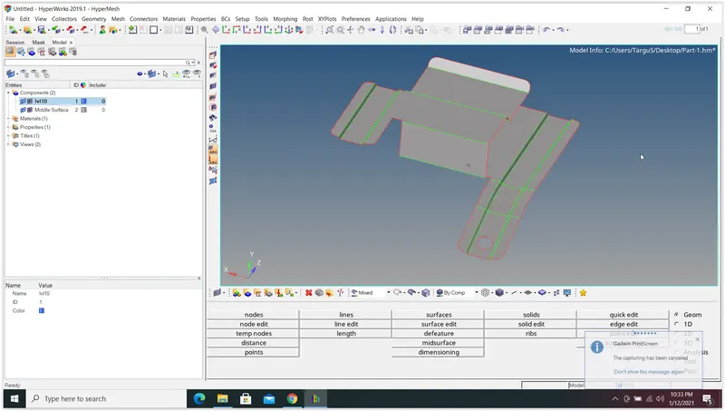
Defeaturing the small gap using the replace point option and meshing the midsurface.
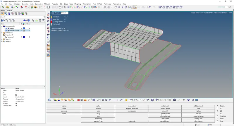
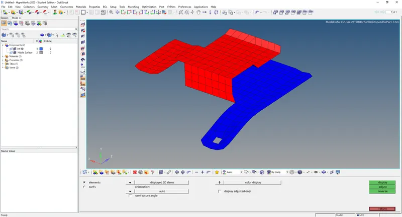
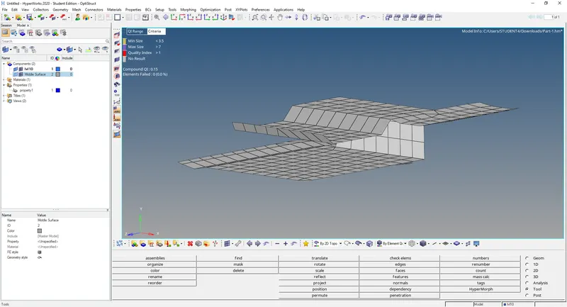
Meshing rest of the surfaces using Automesh & refining using tools in quality index.
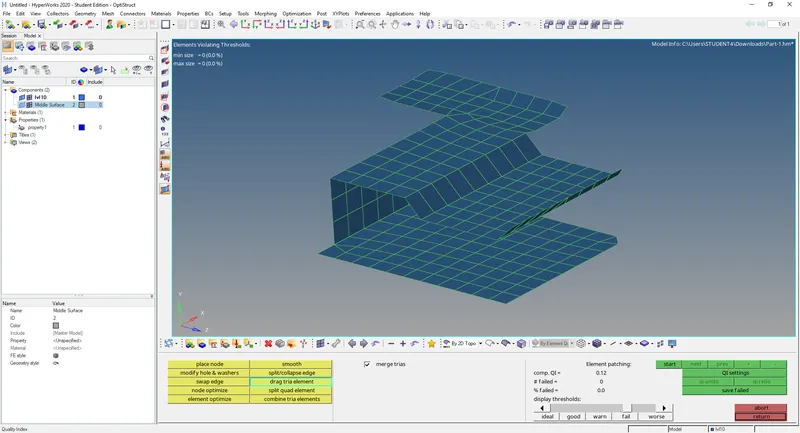
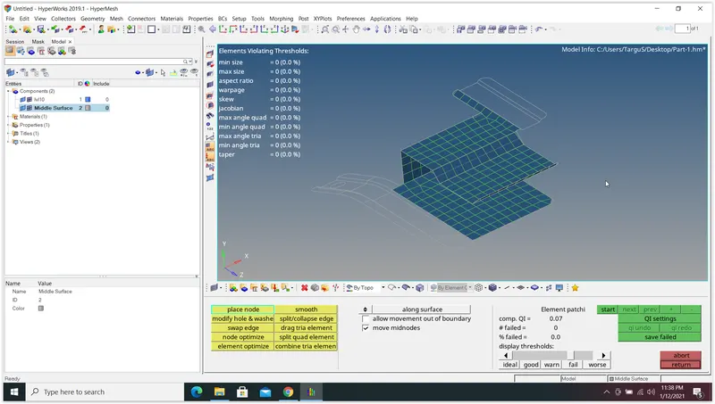
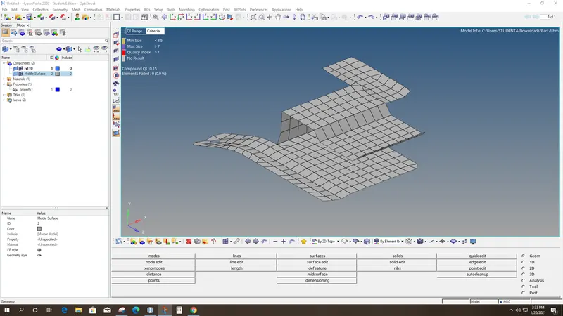
Adjusting the point representing the hole to improve mesh flow. Then Checking for mesh normals and free edges
Part 2
Clearing all the temporary nodes at first using the temp nodes option and then using clear all.
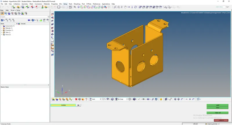
Using the midsurface option selected all the surfaces and obtained the mid surface. But the new mid surface components showed some missing faces.
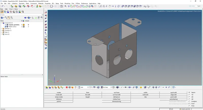
So deleted the mid surface & offsetting each surface using the offset feature under surface edit. The thickness of the component was found to be 2 mm (By using the distance between points). So the offset must be 1 mm inwards while selecting the outer surfaces and duplicate surfaces are to be made.
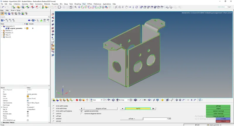
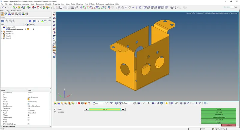
We've to separate the newly created mid surface and assign this to a new component. for that, we'll use organise under tool. For assigning the mid surface alone to the new component, we've to mask all other surfaces except the desired mid surface.
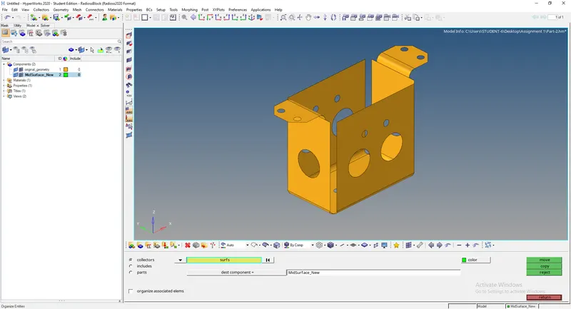
A new component named 'MidSurface_New' was created in the Model browser and was set as the dest component.
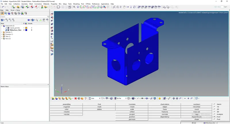
Ignoring the holes of smaller diameter (=>5mm) and using unsplit surf function under quick edit to fill these holes.
First proceeding with the meshing of the base of the bracket. Element size is chosen as 5mm. Points at the ends of the base weren't properly aligned. So point replace option was used to fix it.
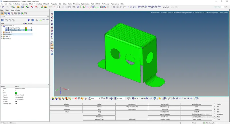
Similarly, the side face was meshed with the same element size.
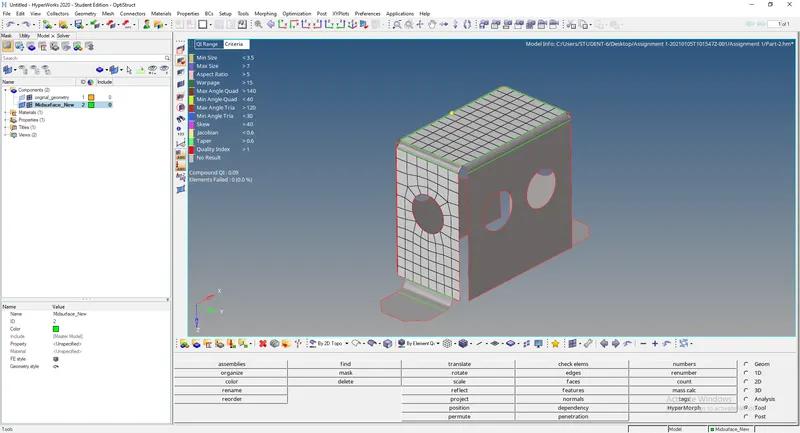
Element quality criteria were set according to the question and quality was checked and corrected using qualityindex.
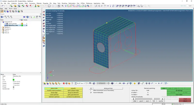
The meshing of adjacent sides is finished so that it can be later reflected into the symmetric surfaces.
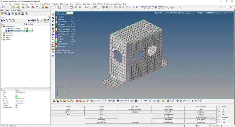
Maximum triangles & rotating quads were removed to ensure proper mesh flow. Necessary mid nodes were created and the Reflect feature was used to reflect the mesh to the symmetric face.
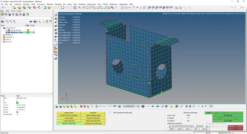
Finally, just making sure that the mesh normals are properly aligned and all free edges are removed.
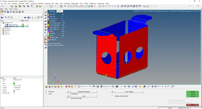
Part 3
First checking for any geometry errors.
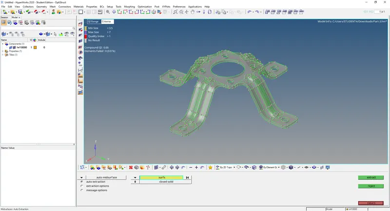
Taking midsurface using automidsurface function under midsurface option
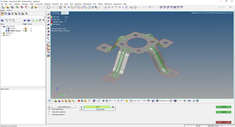
Removing holes under 5mm diameter using defeature option
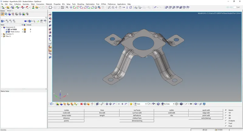
Simplifying the midsurface by deleting small surfaces
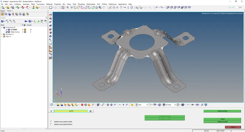
Meshing the topmost surfaces after toggling some lines.
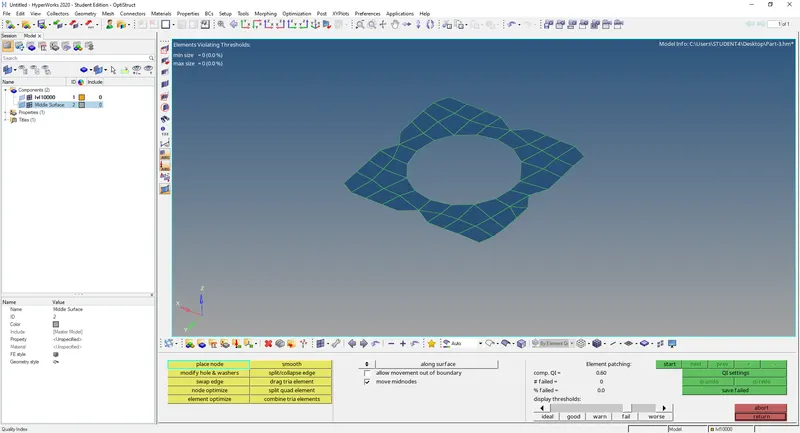
Now meshing the arm after adjusting the point representing circle (to obtain better mesh flow).
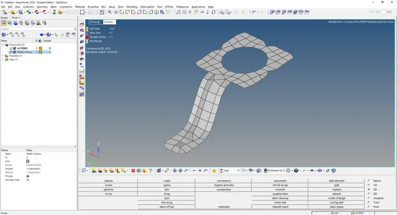
Similiarly meshing rest of the arms.
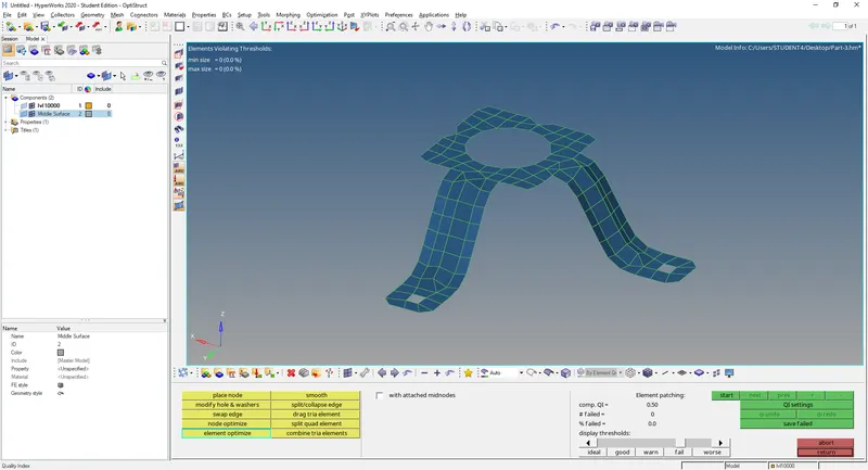
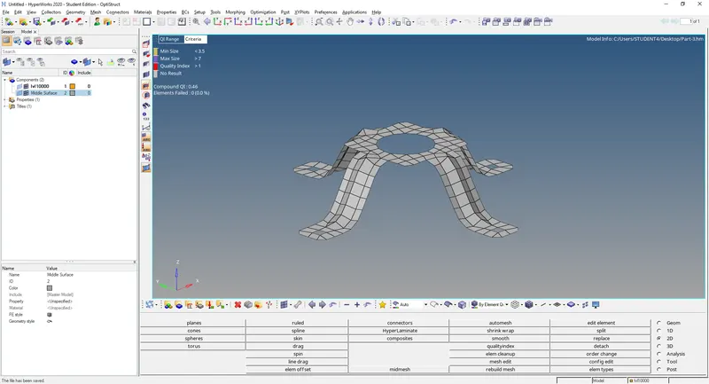
Checking for mesh normals and removng free edges