Assignment 1
OBJECTIVE:
1. To carry out geometry cleanup operation on the given parts : a) Practice b) Clip Repair c) Mounting Bracket
2. To eliminate all free edges and convert all of them into refined geometry.
- Clean the geometry.
- Extract midsurface.
- Clean midsurface geometry.
- Ignore holes less than dia 5mm.
- Create 2D mesh with target length 5mm, min 3.5mm max 7mm.
- And assign proper thickness, by creating a generic property.
- Then Save in .hm format.
SOLUTION:
The objective of the project is to perform meshing of the given components. Three different parts has been provided for this assignment. As part of the task, all free edges needs to be eliminated, mid surface and geometry clean-up has to be performed by ignoring any holes having less than 5mm diameter and the components has to be meshed using 2D elements with target element size of 5mm. The final mesh should have elements with minimum size of 3.5mm and maximum size of 7mm. The meshing should be done using mixed elements and maintaining minimum tria element concentration. The final mesh has to satisfy the given quality parameters and should have a good mesh flow. Finally, proper thickness has to be assigned to the meshed models.
The below report explains the general steps followed while meshing each of the given parts, followed by a set of images showing the initial and final results.
Step 1:
Open the given part file in the Hypermesh GUI. Check the part for geometry clean-ups like free edges, duplicate surfaces etc and clear them using the various tools.
Most of the geometry clean-ups can be performed using the tools provided in the quick edit option in the Geom panel. Some common clean-ups performed are as follows:
Free edges in the geometry – mostly can be solved using the toggle edge option by setting proper tolerance values.
Missing surfaces or cavities to be filled – can be created using the filler surface option
Duplicate surfaces – use delete surf option
Create better mesh around holes – use washer split option
Many other clean-up operation will be required depending on the geometry
Step 2:
The mid surface for each part was extracted using auto midsurface option. For this project the extract option was set as offset+planes+sweeps.
Step 3:
After extracting the mid surface, the part was again analysed for geometry clean-ups. All holes having diameter less than 5mm were neglected.
Step 4:
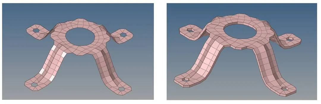
The mesh was created using mixed element of 4mm size using the automesh option in 2D panel. This is a computer generated mesh and requires clean-ups to satisfy the quality parameters and for good mesh flow. To get better mesh flow, re-mesh a selected set of elements, move around the nodes so as to capture the geometry with maximum possible accuracy.
Step 5: Mesh clean up
The mesh generated is supposed to have a good flow and satisfy all quality criterions. Some steps to achieve the same is as described:
- Some modification in the mesh can be brought by controlling the changing the number of elements at the different sections. This action can be performed at the initial step of meshing.
- For removing local element concentration and to imparting good mesh flow, the elements in these areas may be selected and meshed again. Sometimes, multiple iterations may be required to get a good mesh.
- For generating the mesh of required quality, various tools are available in the quality index and elem cleanup options in 2D panel.
- Some commonly used tools for generating good quality mesh includes element optimize, place nodes, combine tria elements, split quad elements, cleanup, automesh, check elements and so on.
Step 6: Property & Thickness
A property card was defined for each part and respective thickness were assigned for each model.
The different meshed parts of the components are as shown:
Part 1:
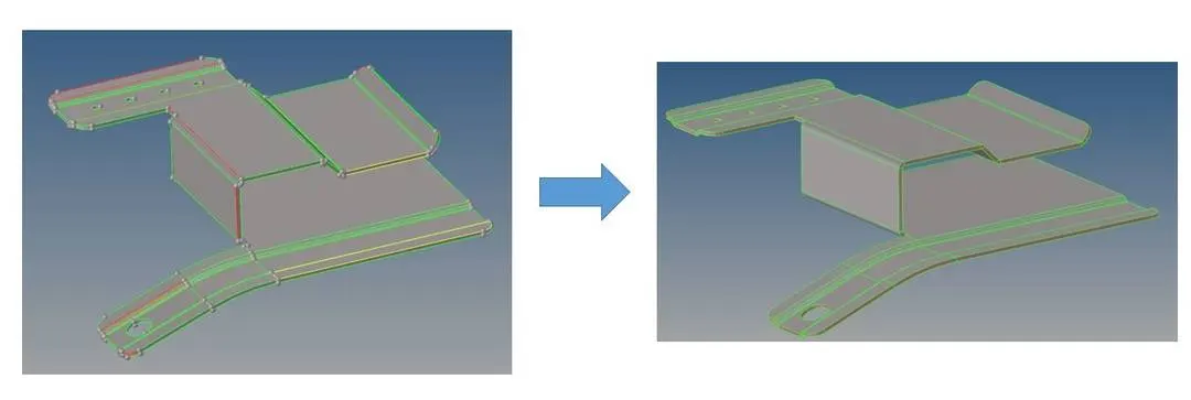
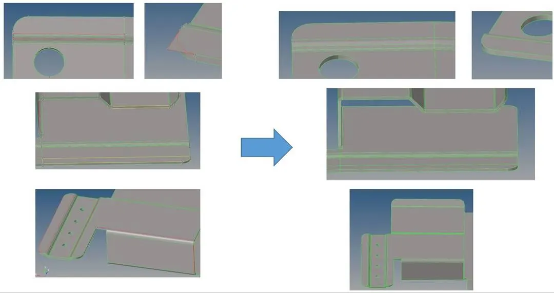
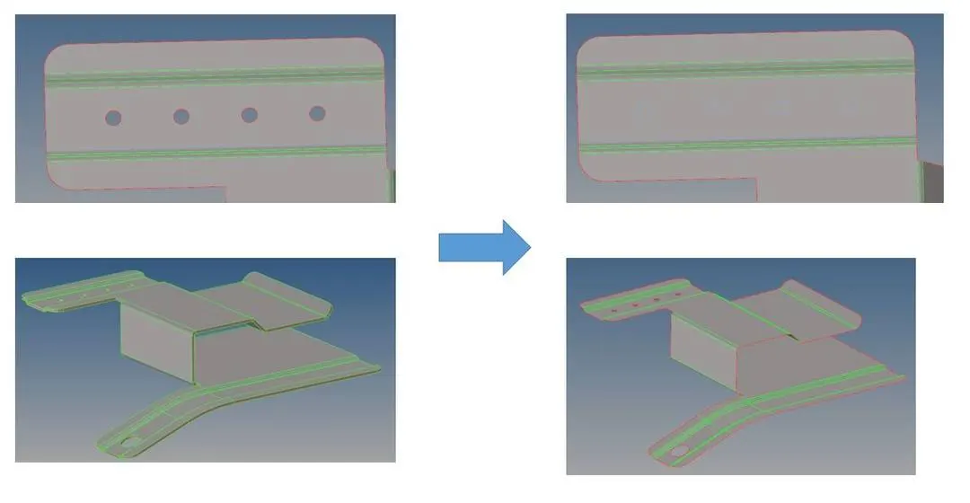
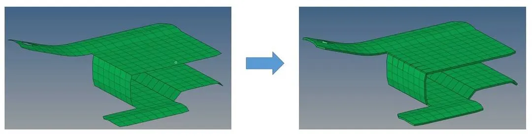
Part 2:
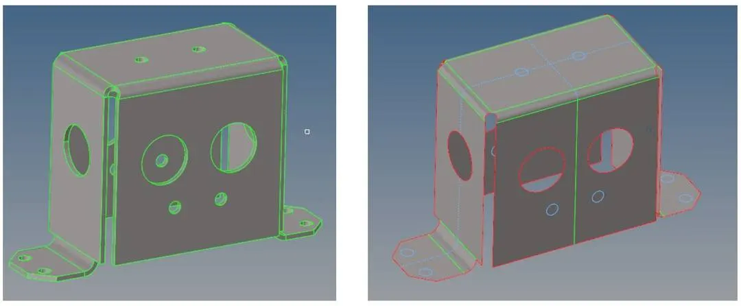
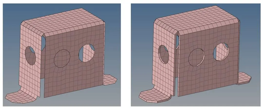
Part 3:
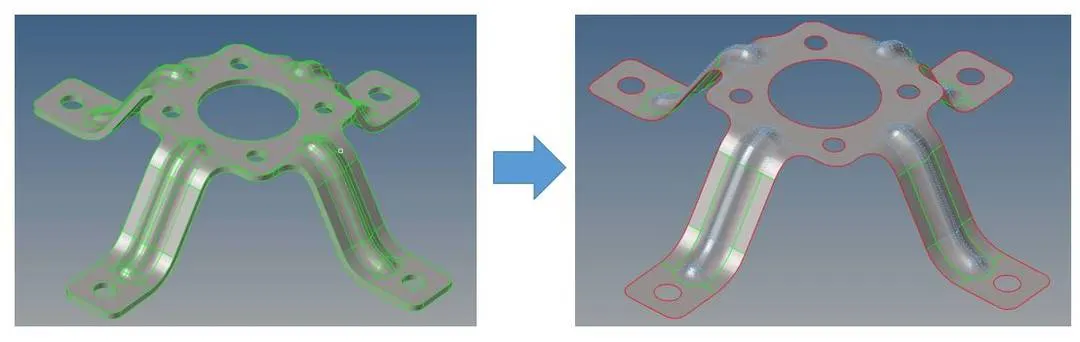
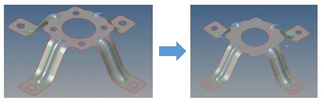
Conclusion:
- Given components loaded into the GUI and geometry cleanup was performed.
- The mid surface for each part was extracted and geometry cleanup was performed on the part.
- All parts were meshed using mixed elements and the mesh was modified to get good mesh flow.
- Further each quality parameter, as defined in the problem statement, was cross checked and necessary changes were incorporated into the mesh.
- Finally, thickness and properties were assigned to the parts.