Assignment 1
Geometry Cleanup Exercise:
Carrying out the geometry cleanup operation on the given files, considering that there should not be any free edges and converting all of them into refine geometry.
AIM -
- Clean the geometry.
- Extract midsurface.
- Clean midsurface geometry.
- Ignore holes less than dia 5mm.
- Create 2D mesh with target length 5mm, min 3.5mm max 7mm.
- And assign proper thickness, by creating a generic property.
Practice
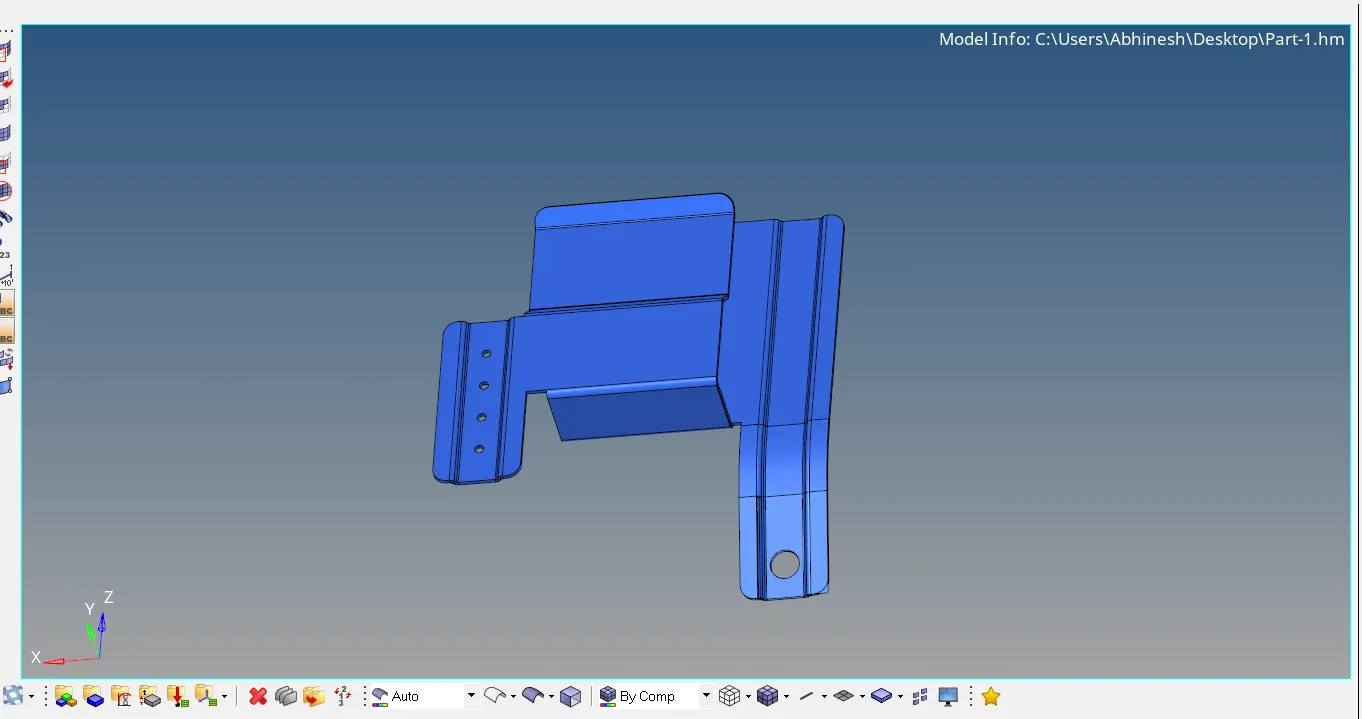
The file is shown below
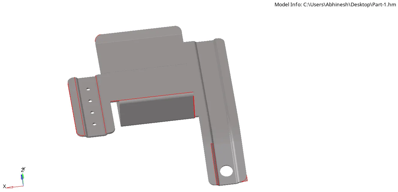
In order to get the free edges click on the visulaization button presrent in the current panel, after selecting the desired selection, in this case "Free Edges", free edges of the file will be shown gets higligted as in the image given below
given below is the shared edges image if the given file
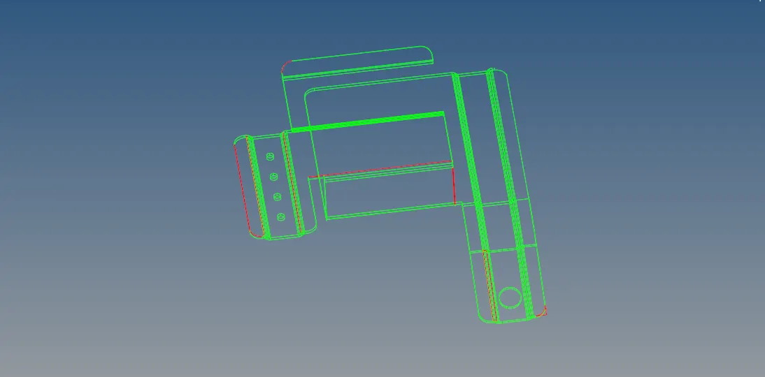
now after seperating free edges and shared edges we get this image as shown below:
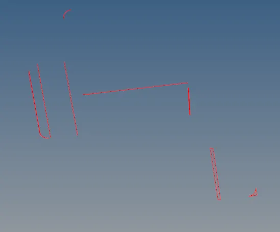
Since we have to convert them into a refine geometry, in order do that we toggle the lines using quick edit option from the panel :
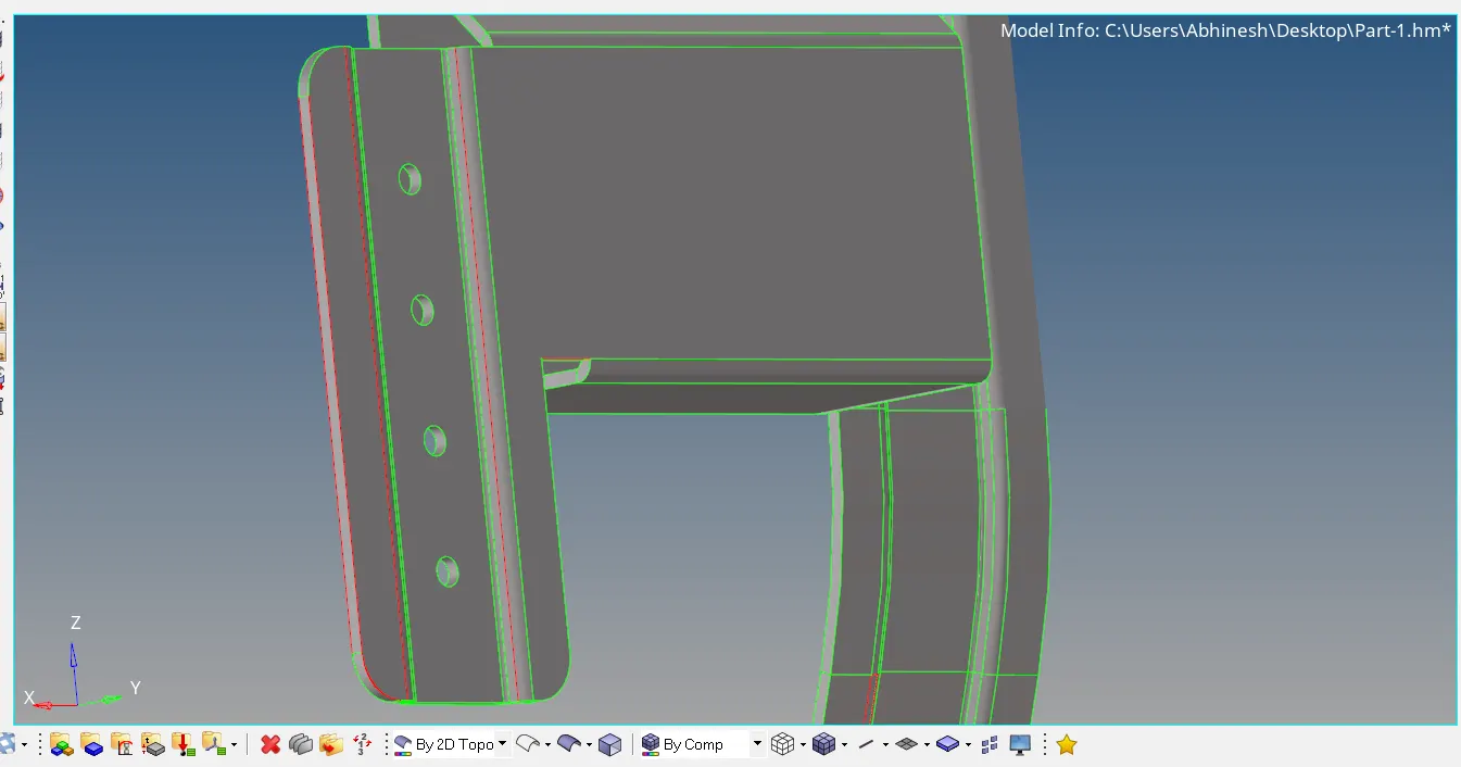
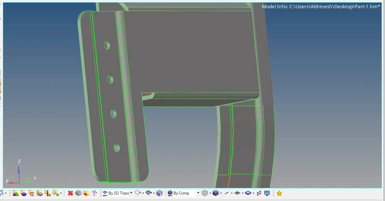
To get rid of the excessive surface we have to trim the excessive part in order to do that we have to select the surface which we have to trim from surface edit as shown in the image below :
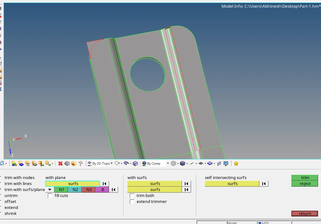
After selecting the exact surface which we have to trim off there will be a green line coinciding in the surface :
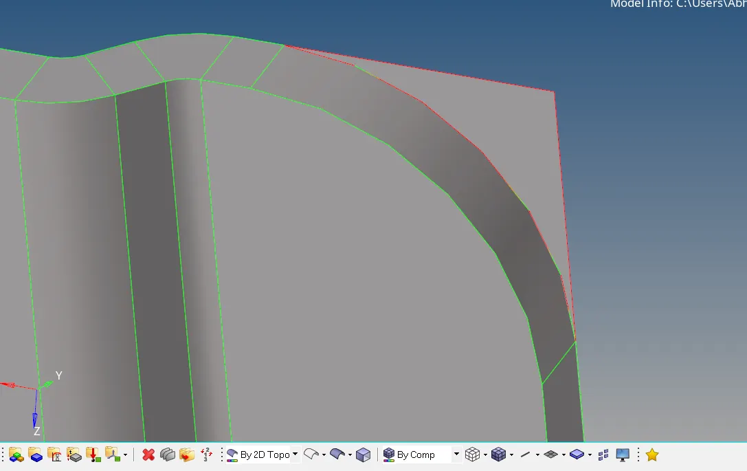
After getiing that green line delete the excessive part by deleting the surface entity :
after toggling the line we get a refined geometry :
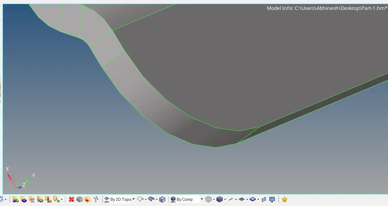
For extracting misdsurface of the object click geormety and then midsurface option, after selecting all the surfaces of the object click extract option.
Now select Middle surface from the component model browser. We'll get the middle surface of the object
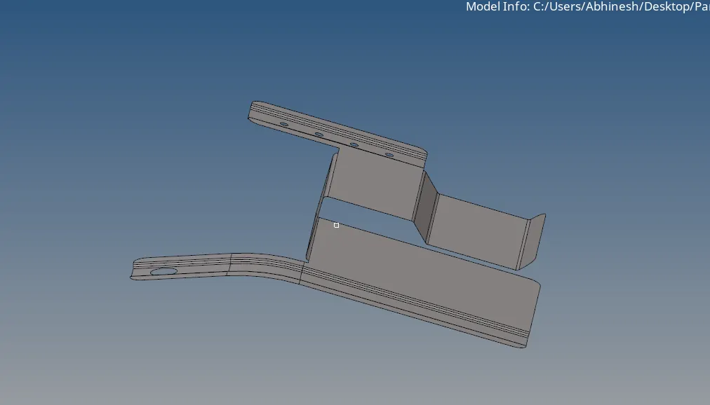
After getting the middel surface, check the diameter of the holes and if less than 5mm neglect the holes and start the process of meshing
Meshing of middle surface of the above given model is shown below
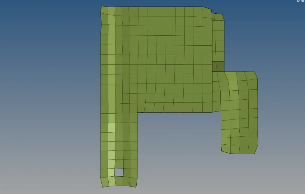
All the element size have been optimized to the given criteria using quality index - clean up tool. The optimized element wise figure is shown below-
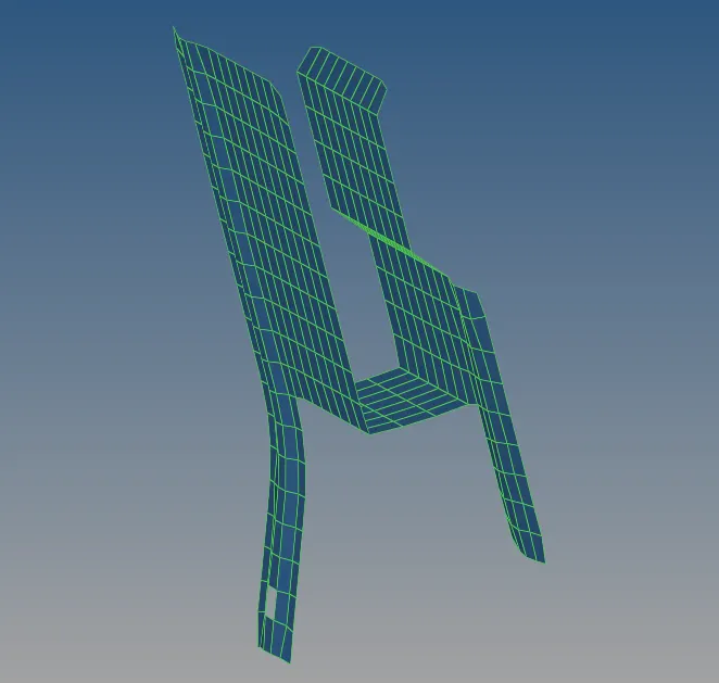
Now, we have to assign thickness to the above middle surface meshing by changing the thickness from property of the material, we get the below image by changing the view to the 2D detailed element representation.
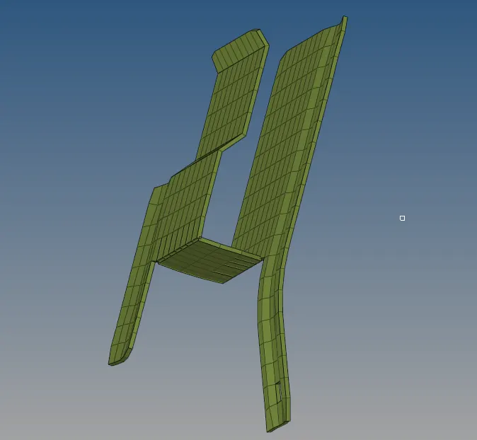
Model 2
The given image of the model is shown below
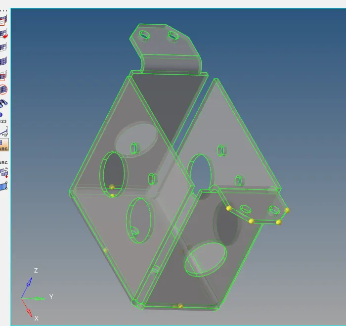
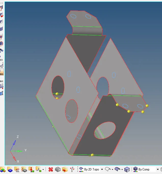
after geometry clean up extract the middle surface as shown below and use filler option to fill the holes below 5mm
Middle surface 2D meshing image is shown below-
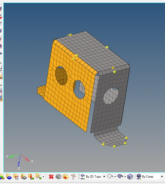
after adding thickness property to the model, it looks like the image below -
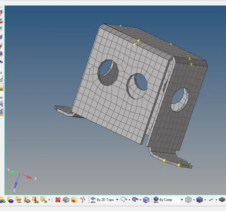
Model 3
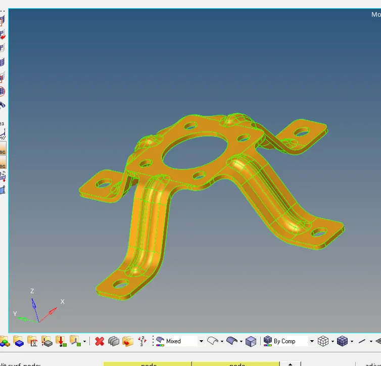
after extracting middle surface using offset parameter from surface edit option we get the following image as shown below -
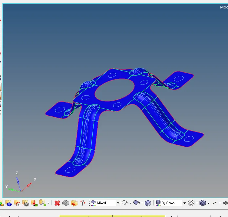
Meshing has been created as shown in the below image using 2D option and then automeshing.
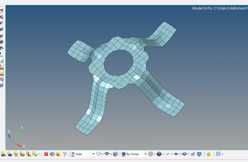
Now for checking the quality of the meshing, open 2D option and click element index button for optimizing the element of the meshing
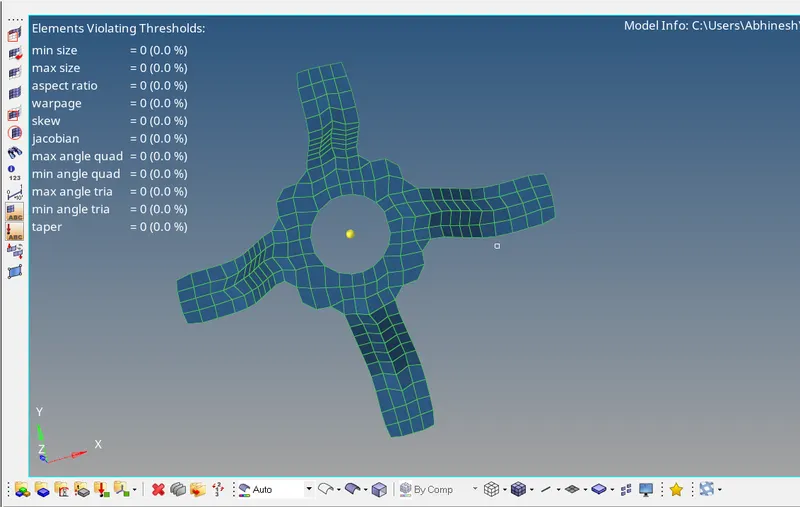
Now assigning proper thickness to the component, adding 1.8mm thickness the above component looks like the image shown below
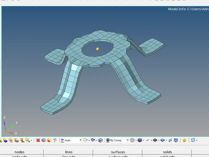
All the three given components now possess refined geometry with no free edges and all the parameters given were carried out successfully.