DESIGN & ASSEMBLY OF YACHT
DESIGNING OF YACHT
OBJECTIVE:
The objective of this project is to design a yacht using different views of images (front, side, top, bottom views) using SOLIDWORKS.
YACHT is a kind of luxury seaway transporter . Designing a yacht is very challenging. Weight, size, capacity, aerodynamics are some factors to be considered while designing. Some yachts are used for racing purpose.
Parts to be modeled for YACHT:
1)Propellor
2)Radar
3)Garage door
4)Hull
5)Front seat
6)Middle seat
7)Rear seat
8)Superstructure
9)Radar mast
Most commonly used tools to create Yacht
PART MODELING:
Modelling in general means to create a virtual prototype of an item. It can be used for various purposes. Consider an engine of a car. It has hundreds of parts. Each part
can be modelled separately and then can be assembled together to get the engine's final form. This type of modelling is called part modeling.
SKETCH:
- The sketch is a two-dimensional representation of the model. There are different sketch options in the SOLIDWORKS like Linr, Arc, Circle, Rectangle, Spline. These are known as Entities
OFFSET:
- One or more sketch entities, Select the model edges, or model faces by specified distance. for example you can offset sketch entities such as splines or arc, set of model edges, loops, and so on. You can offset infinite lines, arc and splines.
EXTRUDE BOSS/BASS:
- Extrude is a type of feature available in SOLIDWORKS to convert a 2D sketch into 3D model.
FILLET:
- Fillet/Round creates a rounded internal or external face on the part. You can fillet all the edges of the face, Selected sets of faces, Selected edges or Edge loops.
LOFTED BOSS/BASS:
- The loft feature allows you to create complex geometry in single feature. It does this by interpolating surfaces between various cross section of a model. These cross-sections can be sketches, faces or edges. In the loft interface, These cross-sections are considered "Loft profiles".
DOME:
- Select one or more planar or non-planar faces. You can apply domes to faces whose centroid lies outside the face. This allows you to apply domes to irregularly shaped contours.
EXTRUDE CUT:
- Extrude cut is another cool feature which helps to remove materials from the 3D model. It is just the opposite to extrude boss/base feature because it cuts a sketch
profile while extruding. You can cut in both directions and mainly used for creating holes, channels, slots etc.
SPLIT:
- The Split tool is used to project an entity (sketch solid surface, face, plane, ar surface spline) onto other surfaces or curved/planar faces. You are also able to split faces
on multiple bodies with one command.
TRIM ENTITIES:
- Select the trim type based on the entities you want to trim or extend. All trim types are available with 2D sketches and 2D sketches on 3D planes. You can use any of the
following trim options: Power trim.
REVOLVE:
- To create a revolve feature Create a sketch that contains one or more profiles and a centerline, line, or edge to use as the axis around which the feature revolves. Click
one of the following revalve tools.
DYNAMIC MIRROR:
- Dynamic mirror is the important tool in solid works. As you sketch the entities, they are mirrored about the pre selected sketch entity.
APPEARANCES:
- An appearance defines the visual properties of a model, including color and texture. Appearances do not affect physical properties, which are defined by materials. Every
material is assigned a default appearance that emulates the look of the material.
COMBINE:
- Combine is the type of feature available in solid works to manually combine the two bodies.
SHELL:
- The Shell Definition Property Manager is used to define the thickness of thin and thick shell elements.
CHAMFER:
- A cut on the edge or corner of something that makes it slope slightly rather than being perfectly square.
CIRCULAR PATTERN:
- The circular parent bodies/ features are used to create a different number of instances required to create the pattern circularly.
LINEAR PATTERN:
- The linear parent bodies/ features are used to create a different number of instances required to create the pattern linearly.
SURFACE MODELING:
Surface modeling gives you the ability to build out a visual representation of an object's exterior and its contours. In other words, it's a surface. Parts like seat fuel tank of classic 350 are surface modeled.
LOFTED SURFACE:
- Loft Surfaces are surfaces generated by multiple 3D Curves or existing edges creating a smooth tangency between the selected curves.
SWEPT SURFACES:
- Sweep Surfaces are surfaces that are generated from a section curve positioned along a path.
FILLED SURFACE:
- The Filled Surface feature constructs a surface patch with any number of sides, within a boundary defined by existing model edges, sketches, or eurves, including
composite curves.
SURFACE TRIM:
- Primarily used to cut away material from a surface, and provides two modes: Standard and Mutual.
EXTEND SURFACE:
- Extend Surface is used to extend the surface which is already created. There are different options available on the extended surface. We can extend the surface as same
surface or we can extend the surface tangent to the surface.
SURFACE KNIT:
- Surface knit is used to knit the two free edges/open edges of the surfaces together. Also it reduces the gap between the two edges of the surface.
Design methodology
- Placed different views of images for our reference to proceed.
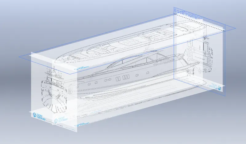
Adjusted the images as per my convenience and saved it as Blueprint.
Note: Instead of modelling whole yacht, Seperated into few parts & assembled it.
Features used to create Blueprint
- Sketch plane
- Sketch picture
Part-1 : Propellor
- Sketched base or centre diagram of the propellor and extruded it as per the dimensions.
- By using different planes completed other parts of the propellor.
- Used circular pattern for making multiple wings in propellor.
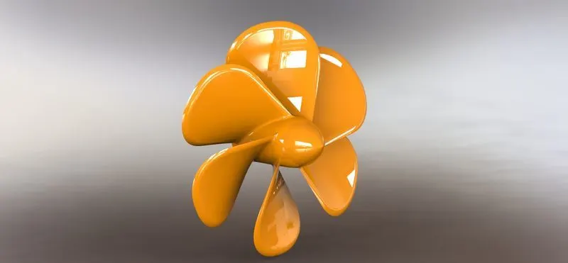
Features used to create Propellor
- Sketch
- Fillet
- Extrude boss
- Revolve
- Loft
- Circular pattern
- Appereance
Part-2 : Radar
- As like before made base diagram of the radar with given dimensions.
- Using some features options built the radar.
- Used text command for creating texts on the model.
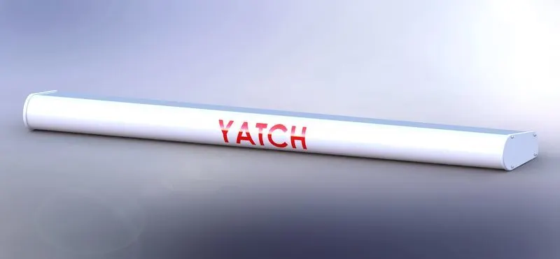
Features used to create Radar
- Sketch
- Extrude boss
- Fillet
- Text
- Appearence
Part-3 : Garage Door
- Selected a proper plane to start the sketch.
- Started to sketch as per the given dimensions.
- Used few features to create this garage door.
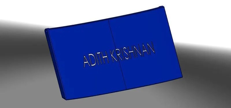
Features used to create Garage Door
- Sketch
- Extrude boss
- Fillet
- Text
- Appearence
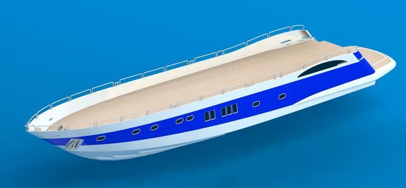
Part-4 : Hull
- Started the sketch with the help of Blueprint.
- Traced the sketch with the help of Blueprint.
- Different types of sketch tools & planes are used to create sketches.
- By using Different Features & Surfaces to completed the hull.
- Finally added some decals on hull for outer look.
Features used to create Hull
- Sketch
- Plane
- Extrude boss
- Extrude Surface
- Surface loft
- Trim
- Surface trim
- Sweep
- Split
- Cut extrude
- Fill
- Fillet
- Dynamic mirror
- Appearence
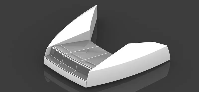
Part-5 : Front seat
- With the help of blueprints started sketching for Front seat.
- Mostly used surface options to build the Front seat of the yacht.
- Completed the Front seat with less time.
Features used to create Front seat
- Sketch
- Plane
- Extrude boss
- Extrude Surface
- Surface loft
- Surface trim
- Cut extrude
- Fillet
- Appearence
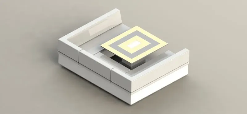
Part-6 : Middle seat
- Top view of the blue print is used to place the Middle seat of the yacht.
- As like Front seat, Middle seat also created with the help of surface options.
- Added decals on the table for rich look.
Features used to create Middle seat
- Sketch
- Plane
- Extrude boss
- Cut extrude
- Fillet
- Appearence
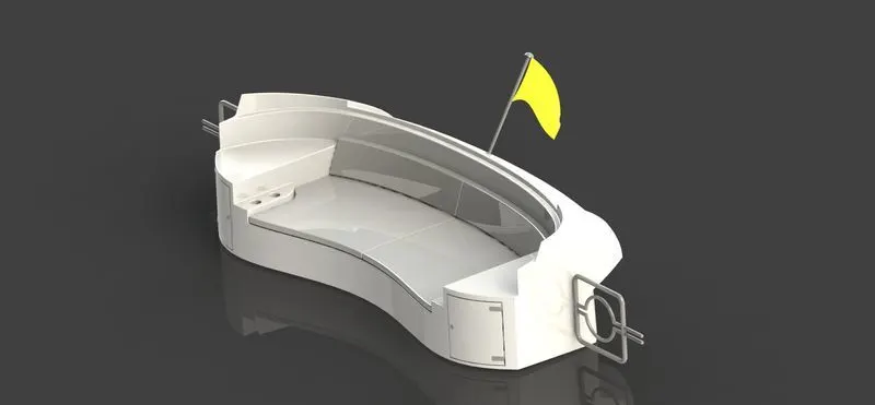
Part-7 : Rear seat
- Followed the same steps as follewed in Front seat & Middle seat.
- This gave more interesting factors to create models (eg: flag).
- Learned new methods for sketching & modelling.
Features used to create Rear seat
- Sketch
- Plane
- Extrude boss
- Extrude Surface
- Surface loft
- Surface trim
- Cut extrude
- Fillet
- Appearence
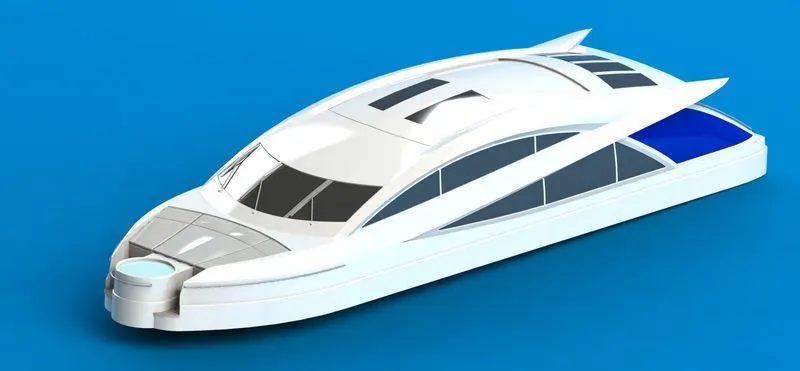
Part-8 : Super Structure
- Started the sketch with the help of Hull surface & Blueprint.
- Traced few areas for reference from Blue print.
- Sketched all Sketches by using Different Sketch tools & planes.
- Modelled whole structure by using different features & surfaces.
Features used to create Superstructure
- Sketch
- Plane
- Extrude boss
- Extrude Surface
- Surface loft
- Trim
- Surface trim
- Sweep
- Split
- Cut extrude
- Fill
- Fillet
- Dynamic mirror
- Appearence
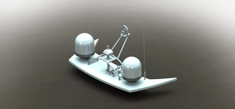
Part-9 : Radar mast
- Started the sketch with help of Super structure surface & Blueprint.
- Used various Sketch tools & Feature tools created the radar mast.
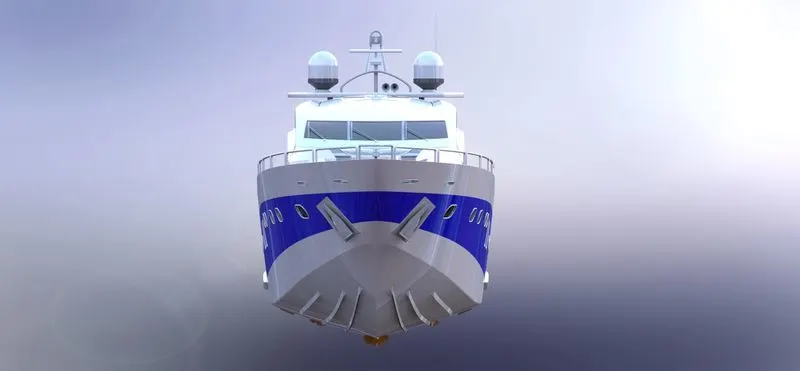
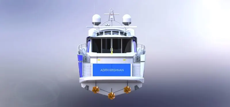
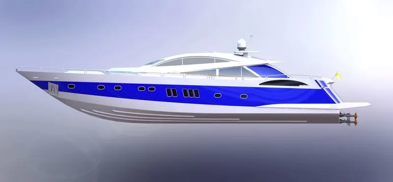
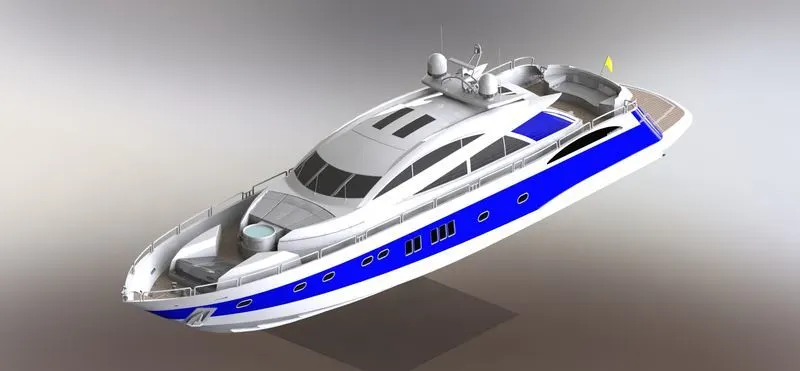
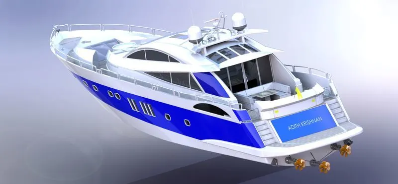
ASSEMBLED MODEL:
- After creating all the parts started assembling one by one.
- Gave suitable relations by using mate options in assembly.
CONCLUSION
By above parts & assembly files, Learned more information & Design thinking approach is been increased while modelling.