Designing, Modelling, Assembly and Photo-Realistic Rendering of American Predator Yacht
Designing, Modelling, Assembly, and Photo-Realistic rendering of American Predator Yacht
Objective:-
# To design and model each component required to make the assembly of American Predator Yacht and finally make a Photo-Realistic rendering of the complete assembly.
# Mastering Various Features of Solidworks (Especially surface-related features such as Swept Surface, Surface Loft, Surface Extrude, Ruled Surface, projecting Curves to form Surfaces as well as fill the gaps by using Surface fill option, use of the surface knit feature to form a solid body from surfaces that we have created ) by designing and modeling of American Predator Yacht.
Introduction:-
- 1. Blueprint setup
- 2. Modeling of propellers, radars
- 3. Modeling of the hull, garage doors
- 4. Modeling of rear seats. middle seats, front seats.
- 5. Creation of superstructure
- 6. Radar Mast
- 7. Final assembly model of Predator Yacht
Design Methodology / Approach:-
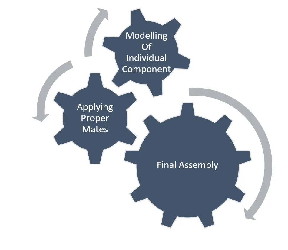
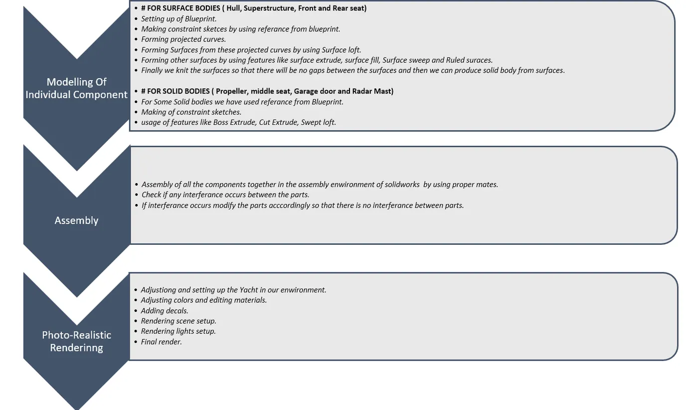
Description:-
1. Blueprint setup
A blueprint is a reproduction of a technical drawing using a contact print process on light-sensitive sheets. Introduced by Sir John Herchel in 1842, the process allowed rapid and accurate production of unlimited copies. It was widely used for over a century for the reproduction of specification drawings used in construction and industry.
A design blueprint is a high-level plan that guides collaborators through the process of designing and contributing to the development of an open course. Its purpose is to visualize the overall “architecture” of the course to guide the design, development, and cooperation process.
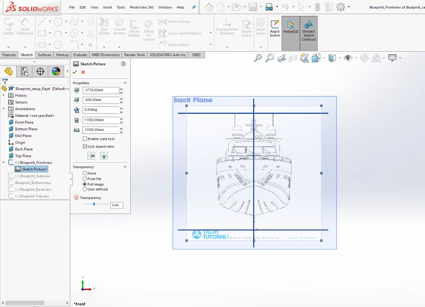
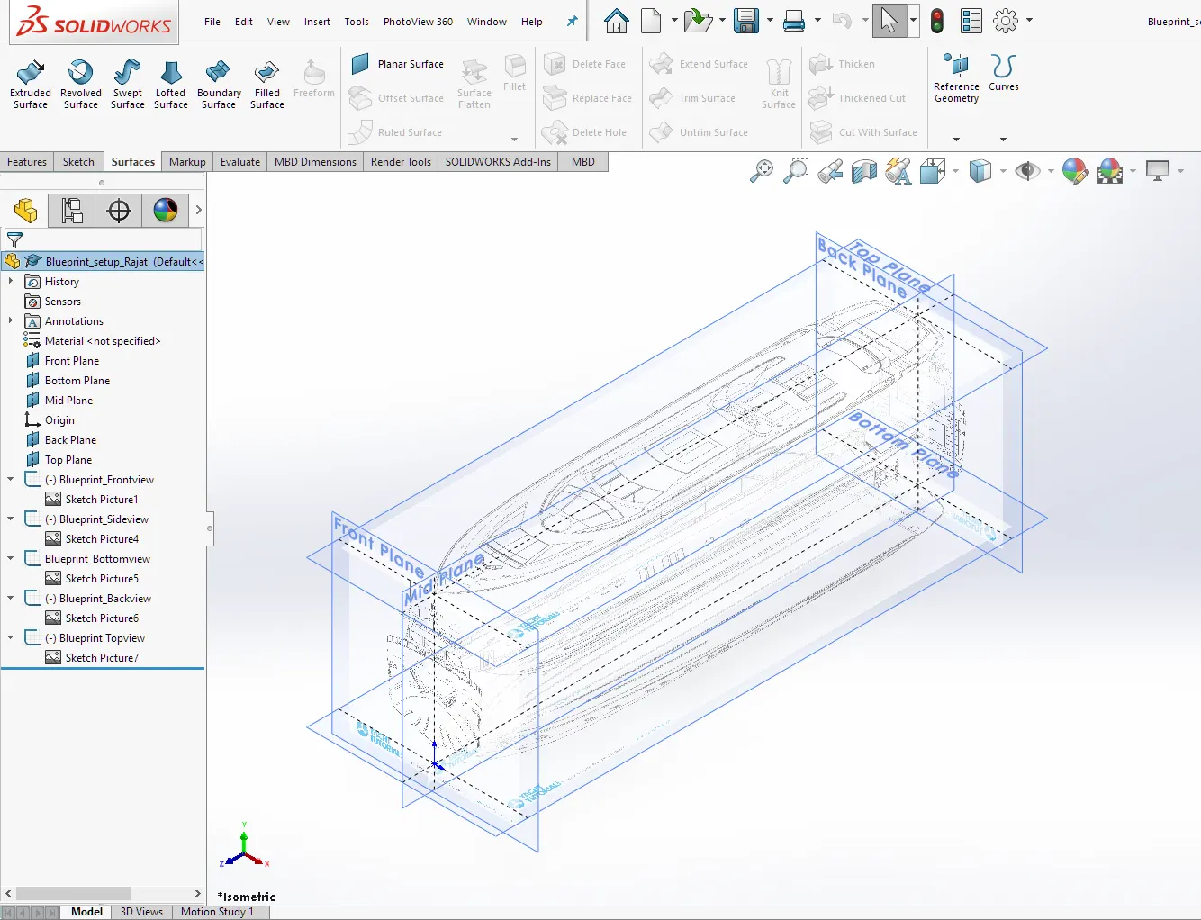
To design and model the yacht we need some kind of reference. that reference may be in form of some concept sketches or the desired views of the product from all the sides (viz. Front view, side view, top view, bottom view, back view). We did the same, we set up blueprints of desired views of a yacht in the Solidworks environment and align each view in proportion to each other. Then we used this blueprint set up as a reference to design all the parts or bodies of the yacht accordingly. We insert the blueprint views in as a sketch and set up it in the proper position.
2. Modeling of propellers, radars.
i. Propeller:-
A propeller is a device with a rotating hub and radiating blades that are set at a pitch to form a helical spiral, that, when rotated, performs an action that is similar to Archimedes' screw. It transforms rotational power into linear thrust by acting upon a working fluid, such as water or air.
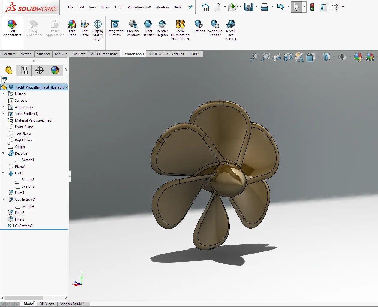
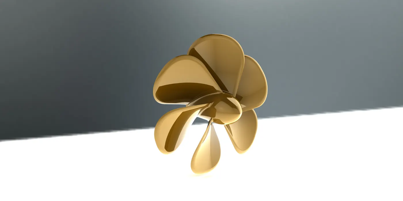
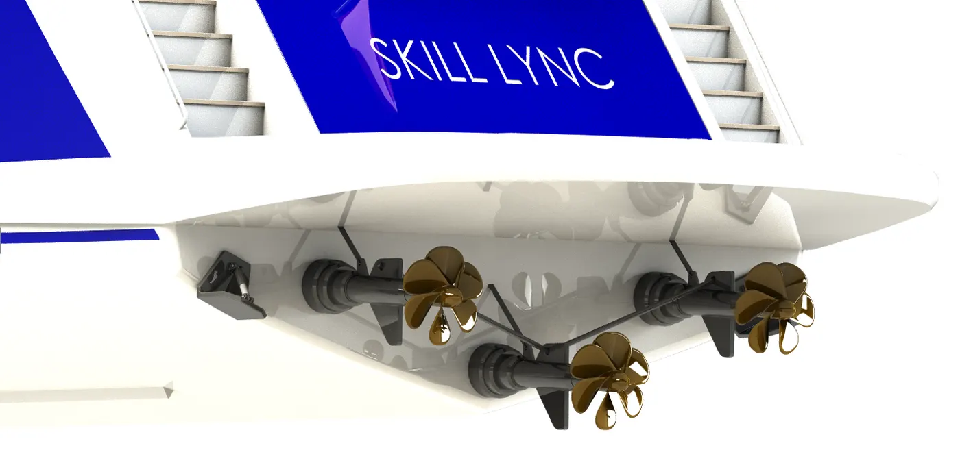
Design Methodology/ Approach:- As we know the design of the propeller is a rotating hub and contains blades on the hub. To create hub we simply used revolve feature. Then to create blades we used loft feature which includes two sketches on different planes. Finally, by using a circular pattern feature we created equally spaced six blades on the surface of the hub.
ii. Radar:-
Radar is a detection system that uses radio waves to determine the range, angle, or velocity of objects. It can be used to detect aircraft, ships, spacecraft, guided missiles, motor vehicles, weather information, and terrain. A radar system consists of a transmitter producing electromagnetic waves in the radio or microwaves domain, a transmitting antenna, a receiving antenna (often the same antenna is used for transmitting and receiving), and a receiver and processor to determine the properties of the objects). Radio waves (pulsed or continuous) from the transmitter reflect off the object and return to the receiver, giving information about the object's location and speed.
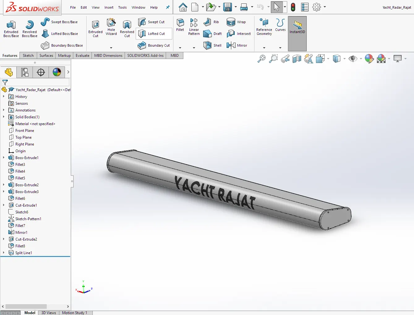
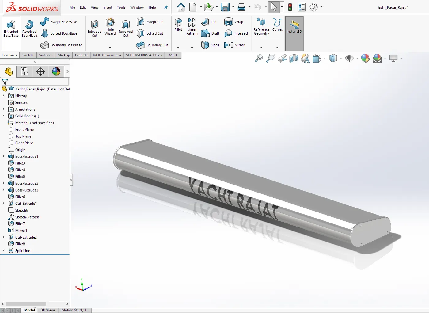
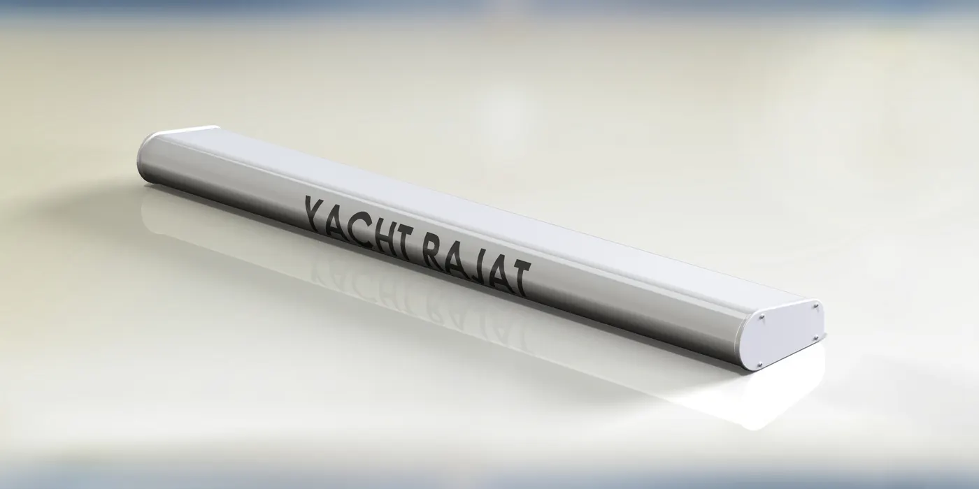
Design Methodology/ Approach:- Design of radar is comparatively simple as it only includes creating some constraint sketches and then extruding them by using boss extrude features. Finally, we used some fillets to finish the part.
3. Modeling of the hull, garage doors.
i. Hull:-
A hull is the watertight body of a ship or boat. The hull may open at the top or it may be fully or partially covered with a deck. Atop the deck may be a deckhouse and other superstructures, such as a funnel, derrick, or mast.
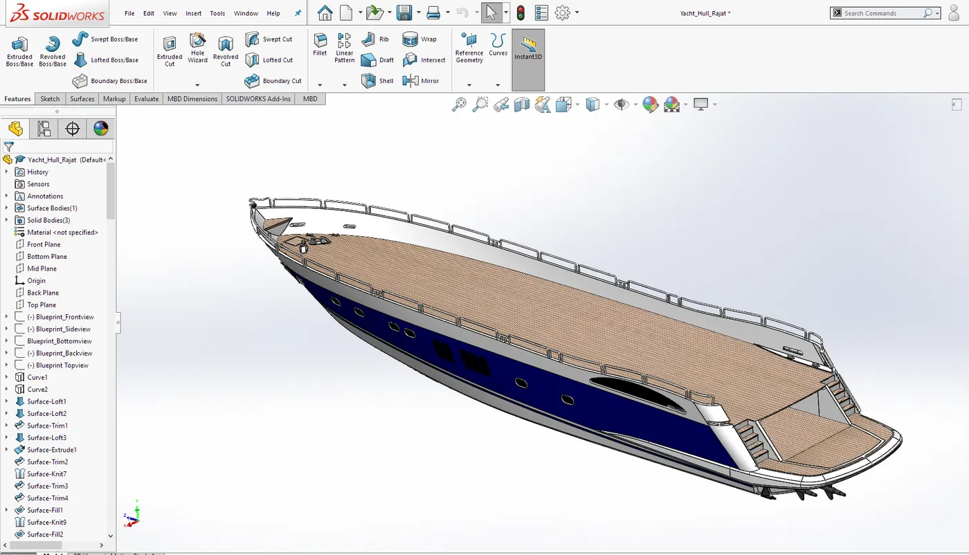
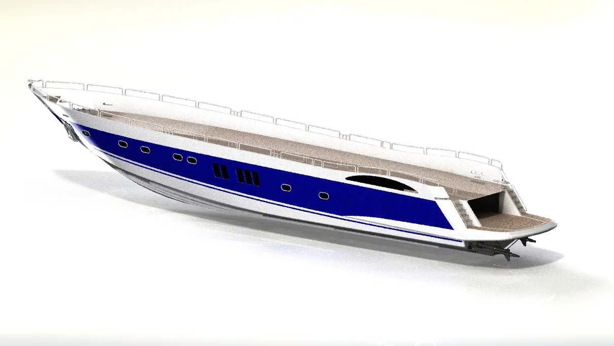
Design Methodology/ Approach:- As we can observe, the hull is a streamlined body consisting of various 3D surfaces. so to design a hull, we require to create a lot of surfaces. We first recall the blueprint setup for the reference for all the curves that we will require to form surfaces. By taking their reference we created a lot of curves and then projected curves. by using these projected curves and boundaries of other surfaces we created surfaces. to create surfaces we used the surface loft feature. We also used the surface fill feature to fill the surfaces in many places. The surface trim feature is used to trim excess surfaces. We then use a knit surface features to join or fill the gap between the curves. Knit surface feature allows us to form the surface body into solid bodies.
ii. Garage door:-
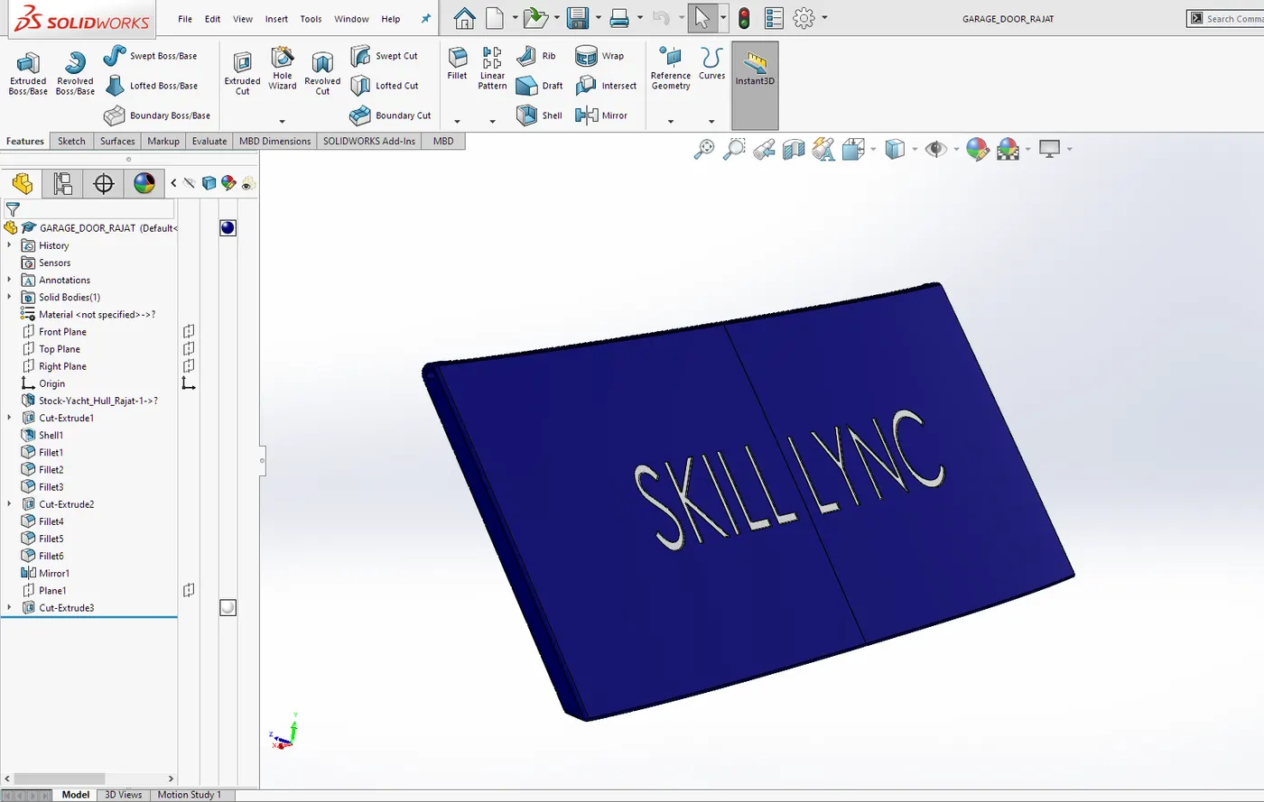
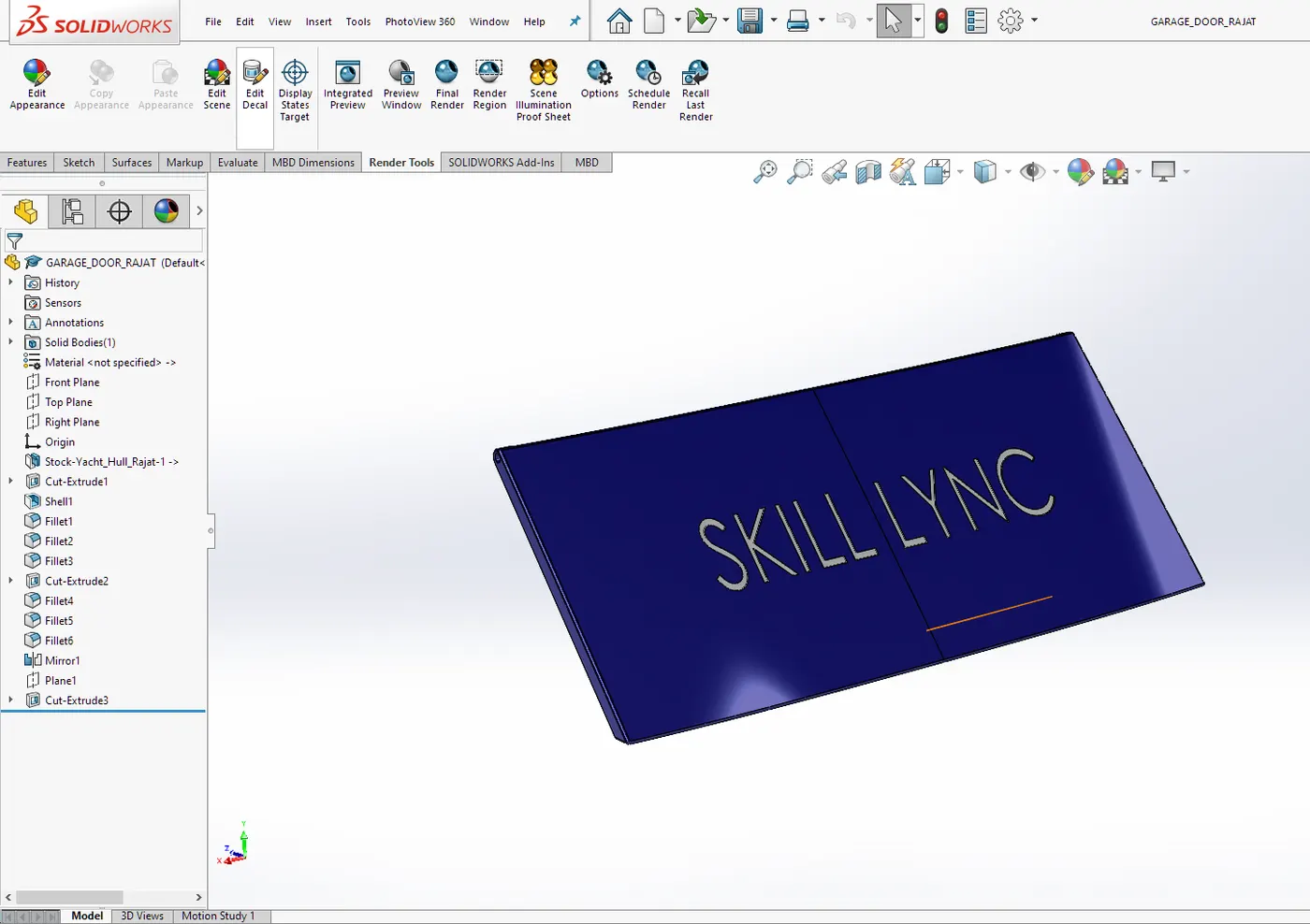
The garage of the yacht is made to carry some useful things such as vehicles or other machinery. Garage consist of a door that may be in hinge connection and will be power operated by some mechanism.
Design Methodology/ Approach:- While designing the hull we created a garage by using a cut-extrude feature. This cut-extruded part or block we saved as a new part for future reference for the garage door. Then we use cut extrude, shell, and fillet features to make the garage door that perfectly fits the garage.
4. Modeling of rear seats. middle seats, front seats
As we know Predator yacht is a sunseeker, so there should be a lot of seats for travelers on the hull for travelers to enjoy the surrounding environment. Considering this requirement there will be seats on the front middle and rear of the yacht. These seats are designed so that their look matches the ergonomics of the yacht.
i. Front seat
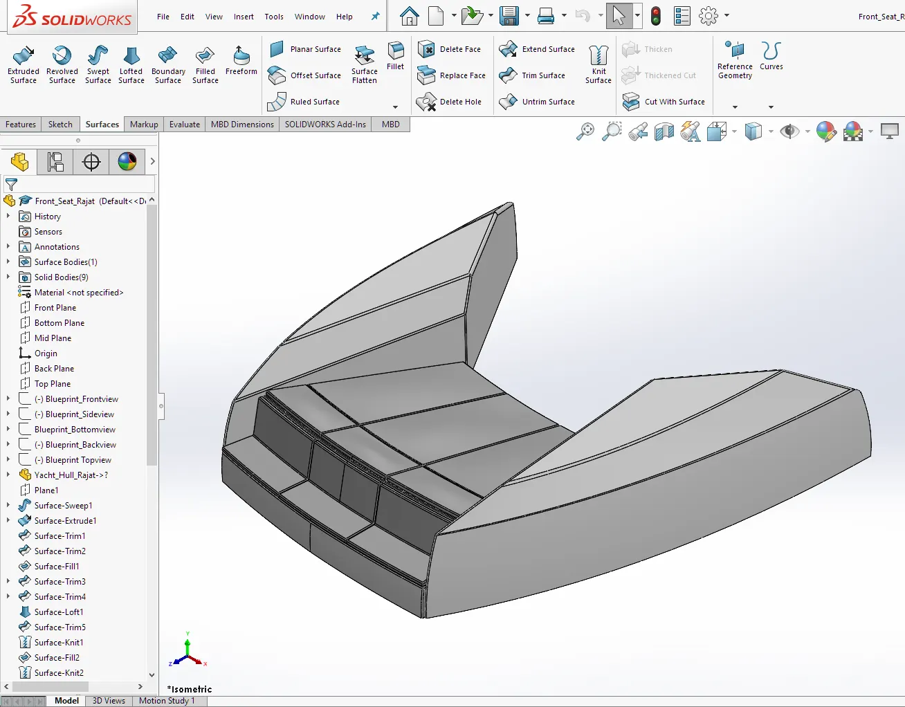
Design Methodology/ Approach:- Front Seat is designed to make its look align to the superstructure ( Predator look). We took reference from the blueprint and created some sketches accordingly. We used features like swept surface and surface extrude to create surfaces and then we used the trim surface feature to remove excess surfaces. Then we used a knit surface tool to connect the surfaces and form a solid body. We also used an offset surface tools to create new surfaces for other bodies like seat cushions. Also, used features like chamfer and fillets are used to give a finished look.
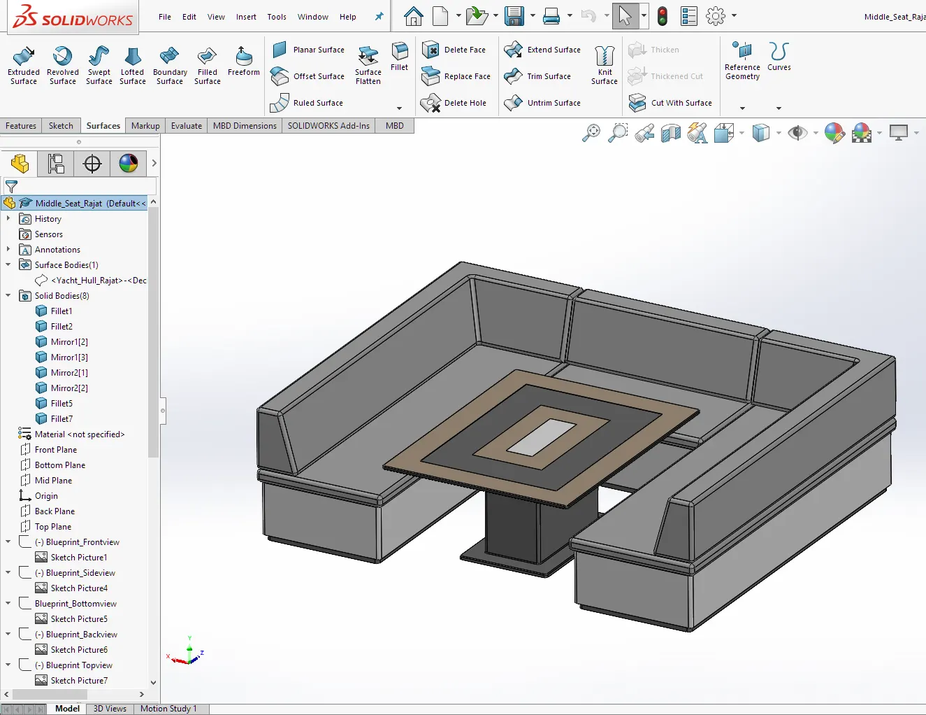
ii. Middle seat
Design Methodology/ Approach:- As we did earlier we took reference from a blueprint and created some sketches. We mostly used boss extrude feature to create bodies. We import some planes to make a gap between the bottom structure and cushions. We then used chamfer and fillet features to give a finished look.
iii. Rear seat
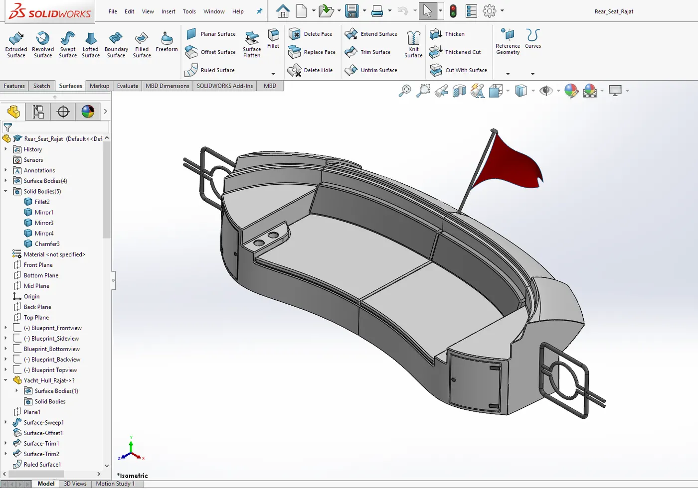
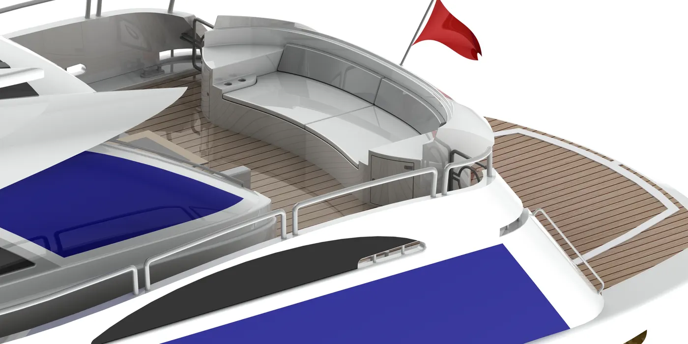
Design Methodology/ Approach:- For the design of the rear seat we take reference from a blueprint and created some basic design sketches. We mostly used a swept surface tool to create surfaces. We also used the surface offset tool to create and give some aesthetic looking surfaces. We used the Rules surface tool to create some extra surfaces. We then used a knit surface tool to join the surface and to create a solid body.
5. Creation of superstructure:-
A superstructure is an upward extension of an existing structure above a baseline. This term is applied to various kinds of physical structures such as buildings, bridges, or ships.
As stated above, the superstructure consists of the parts of the ship or a boat, including sailboats, fishing boats, passenger ships, and submarines, that project above her main deck.
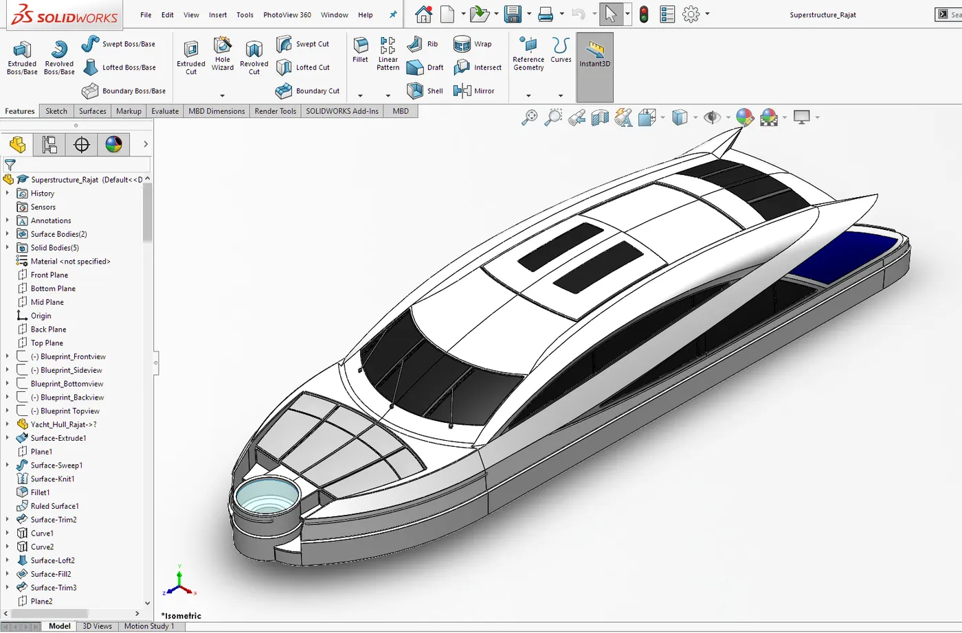
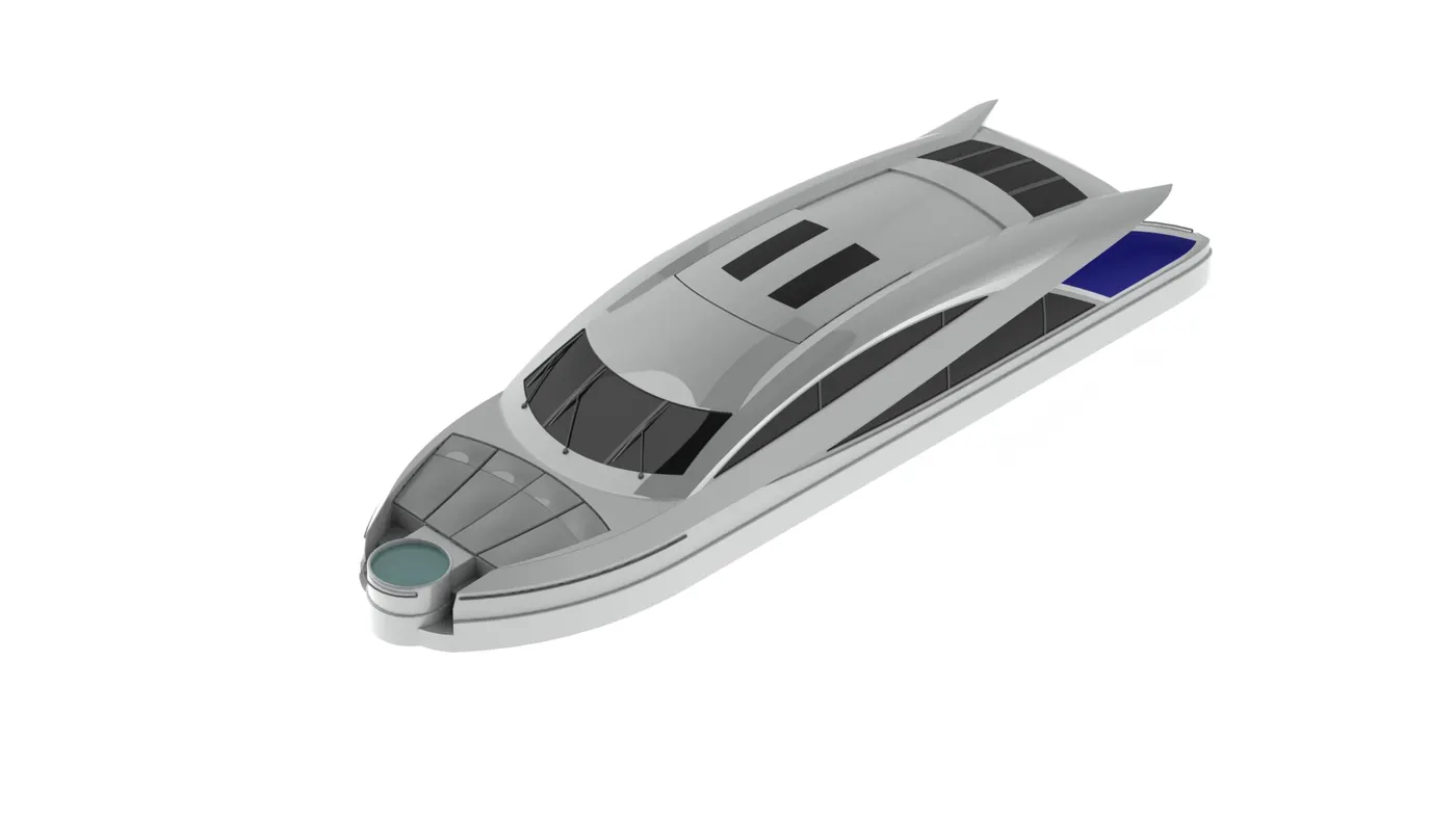
Design Methodology/ Approach:- Design of superstructure is a combination of various surfaces and solid bodies. We take reference from a blueprint and made some sketches that define its outer look. We then created sketches and then we used the project curves feature to create some curves. Further, we used surface tools like surface swept, surface trim, surface loft, ruled surface, the knit surface to create one solid body. After making one solid body, we used to extrude and cut extrude feature to create other accessories and provide a finished look to the superstructure.
6. Radar Mast:-
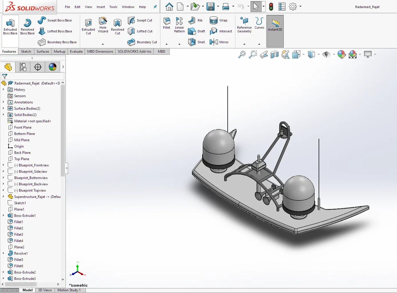
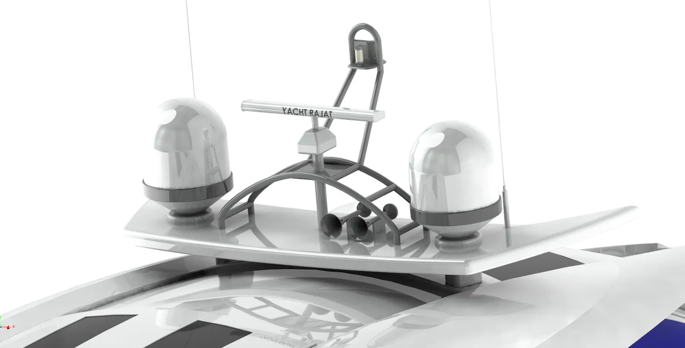
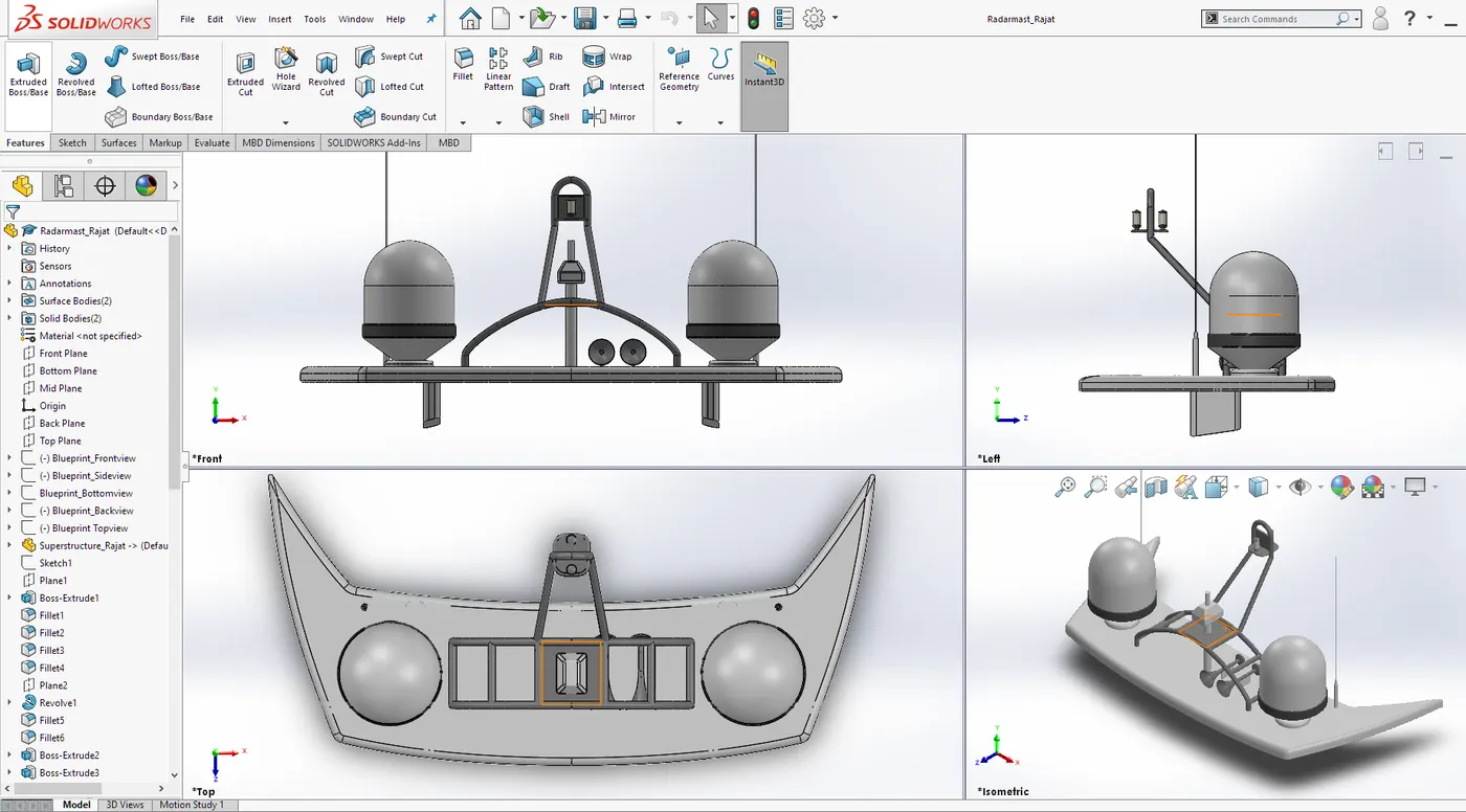
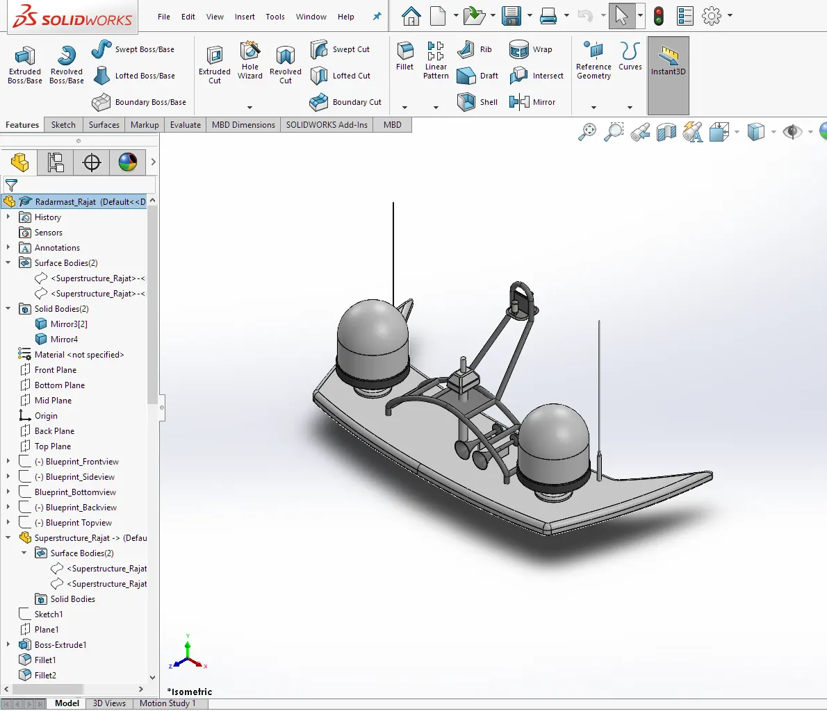
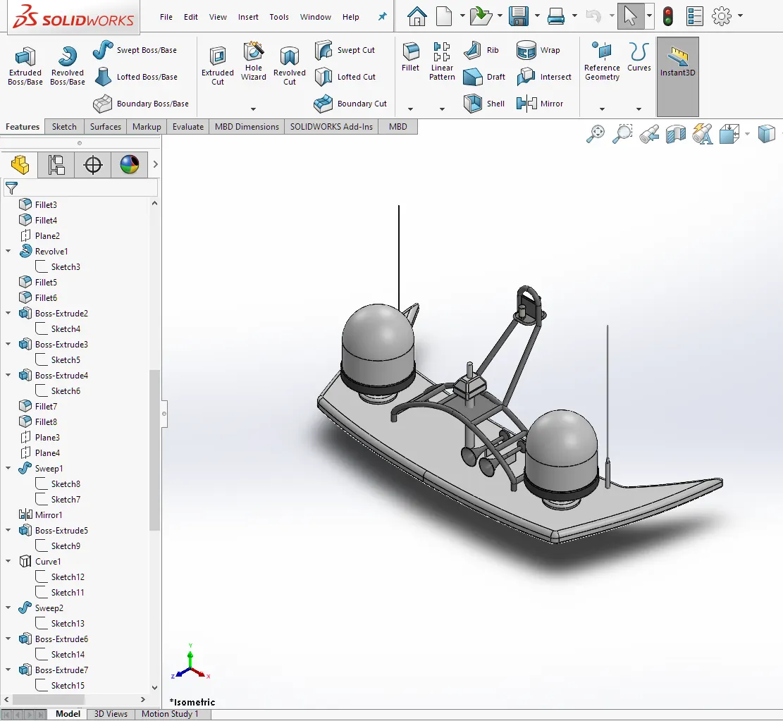
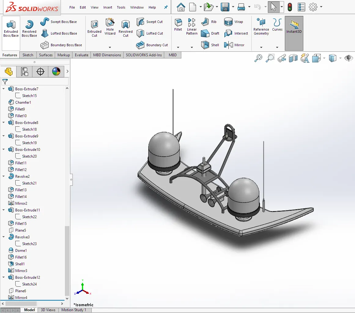
For the design of the radar mast, we take reference from the blueprint as well as a surface that we have created in the hull design for future use. We mostly used extrude and cut-extrude feature to create solid bodies. Revolve feature is used to create horns and dome.
Feature tree for radar mast:-
7. Final assembly model of Predator Yacht:-
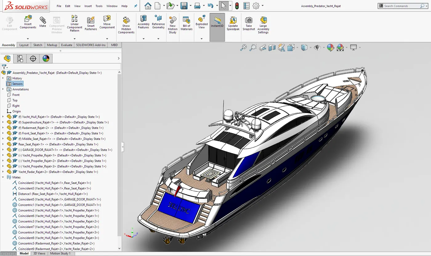
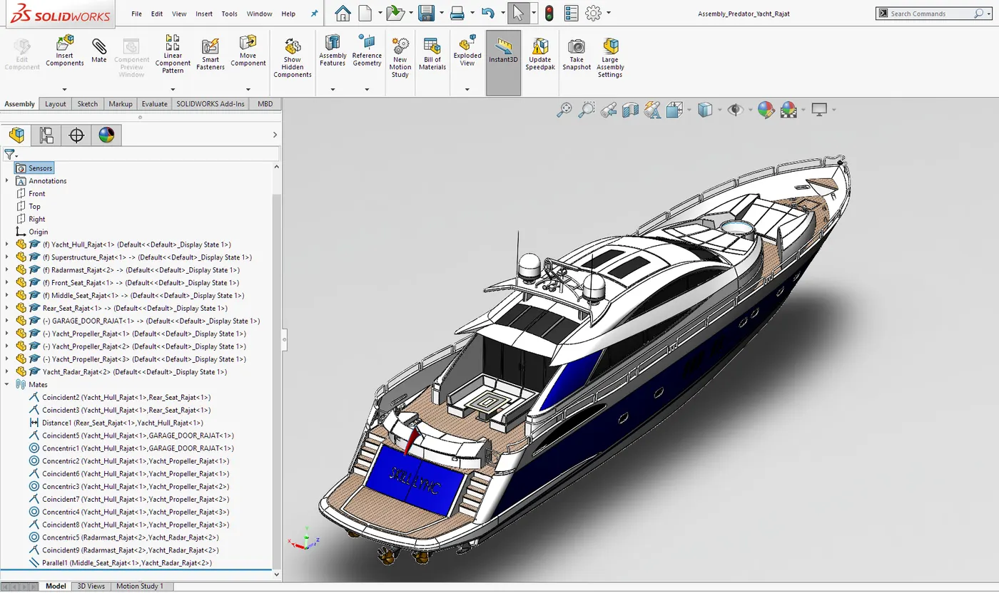
After designing and modeling of all the components of Yacht, we call each part individually in the assembly environment. We first call the hull of the yacht and makes it fixed. Then other components are inserted and proper mates are applied.
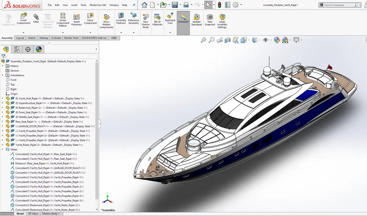
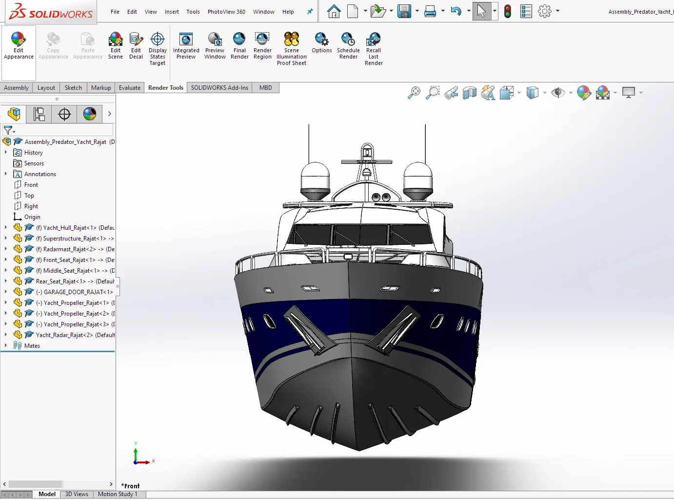
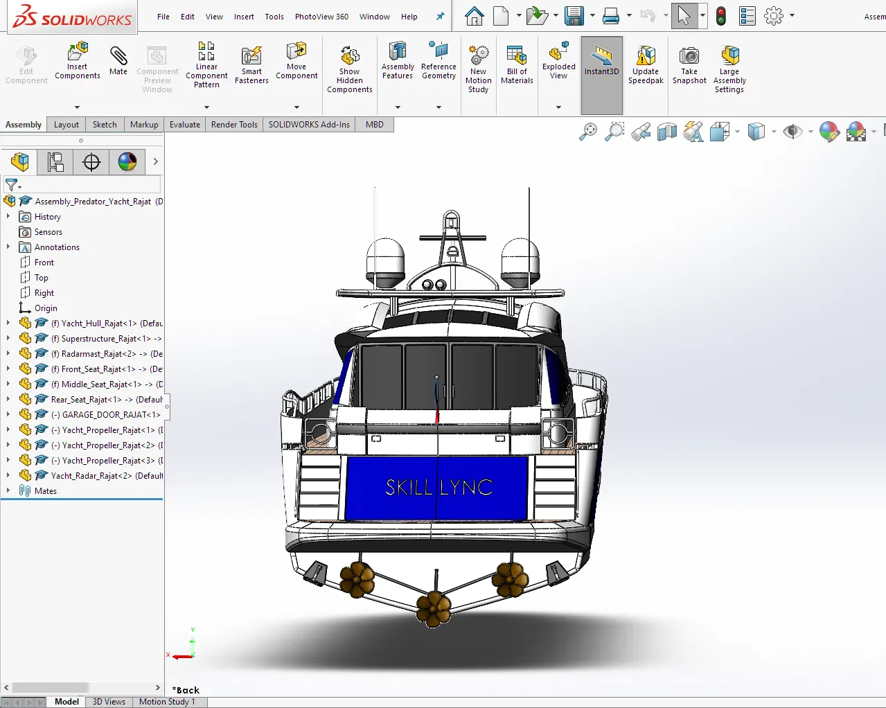
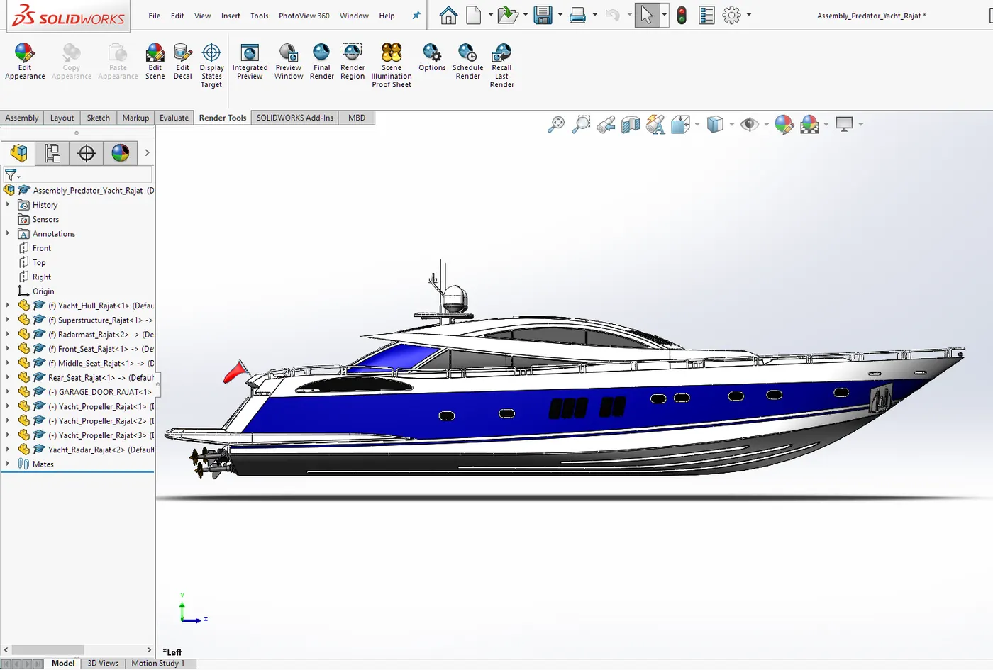
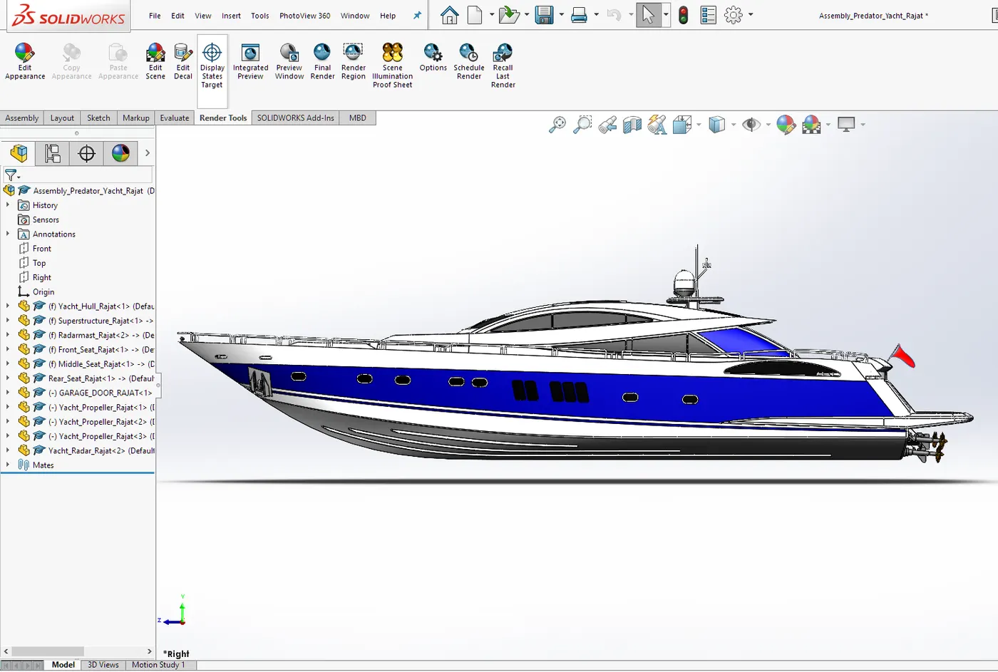
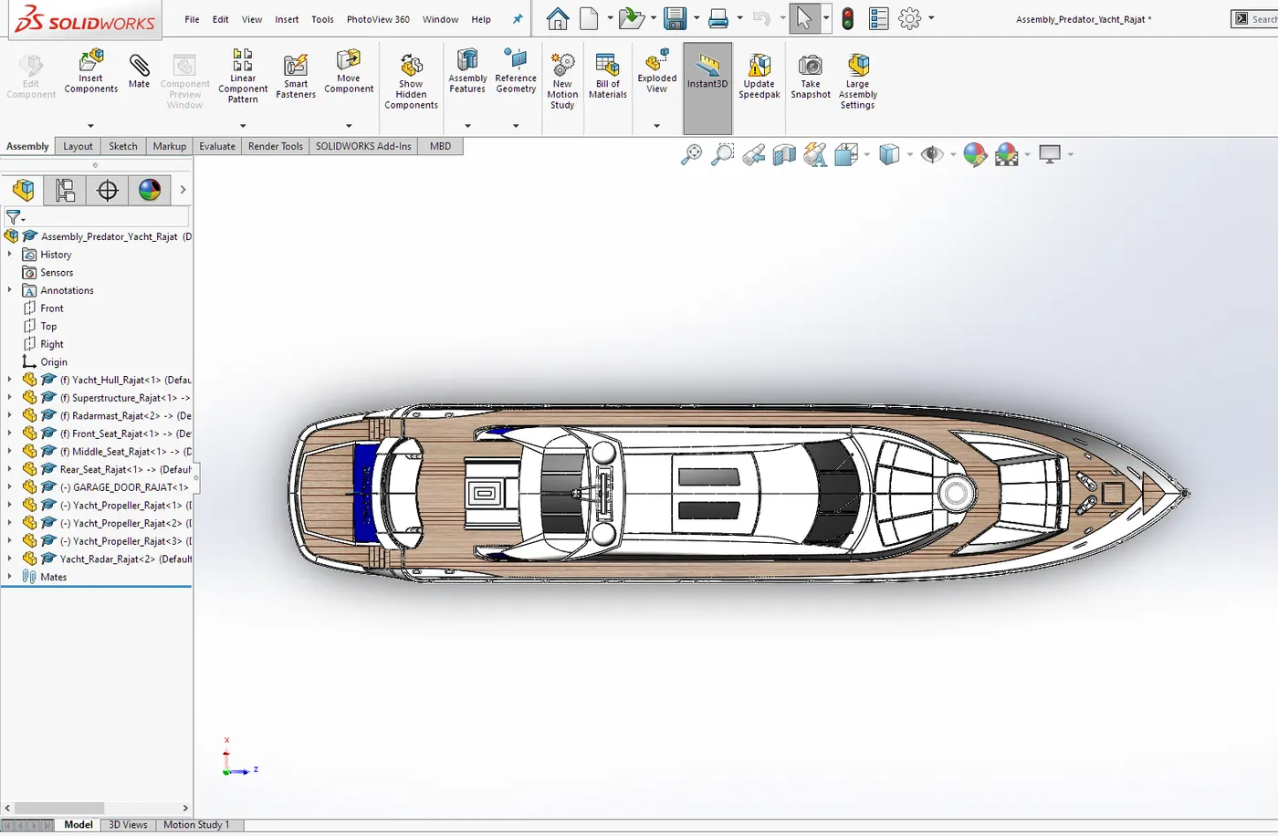
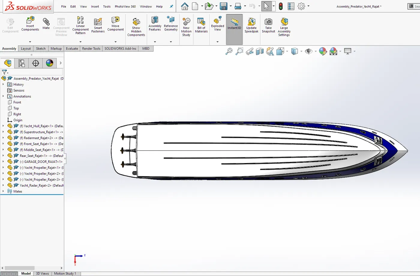
Feature Tree for Assembly:-
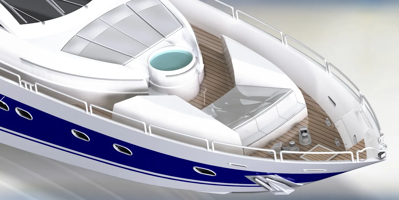
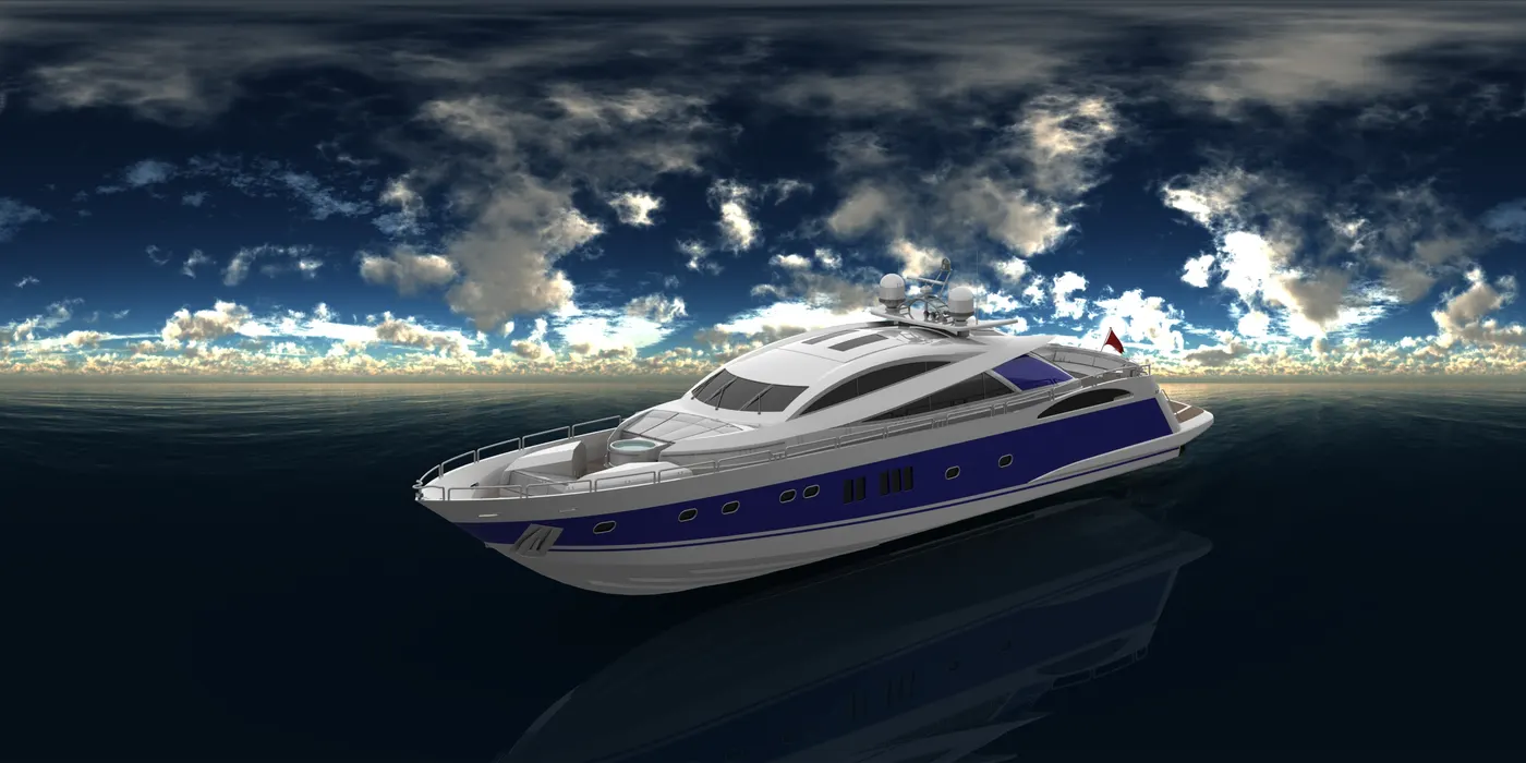
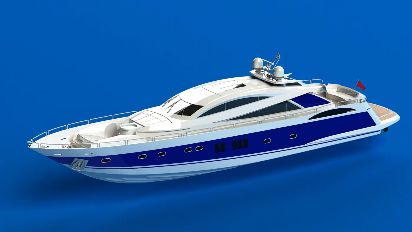
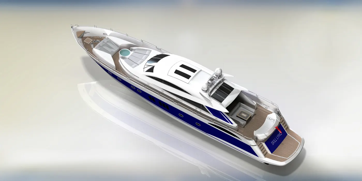
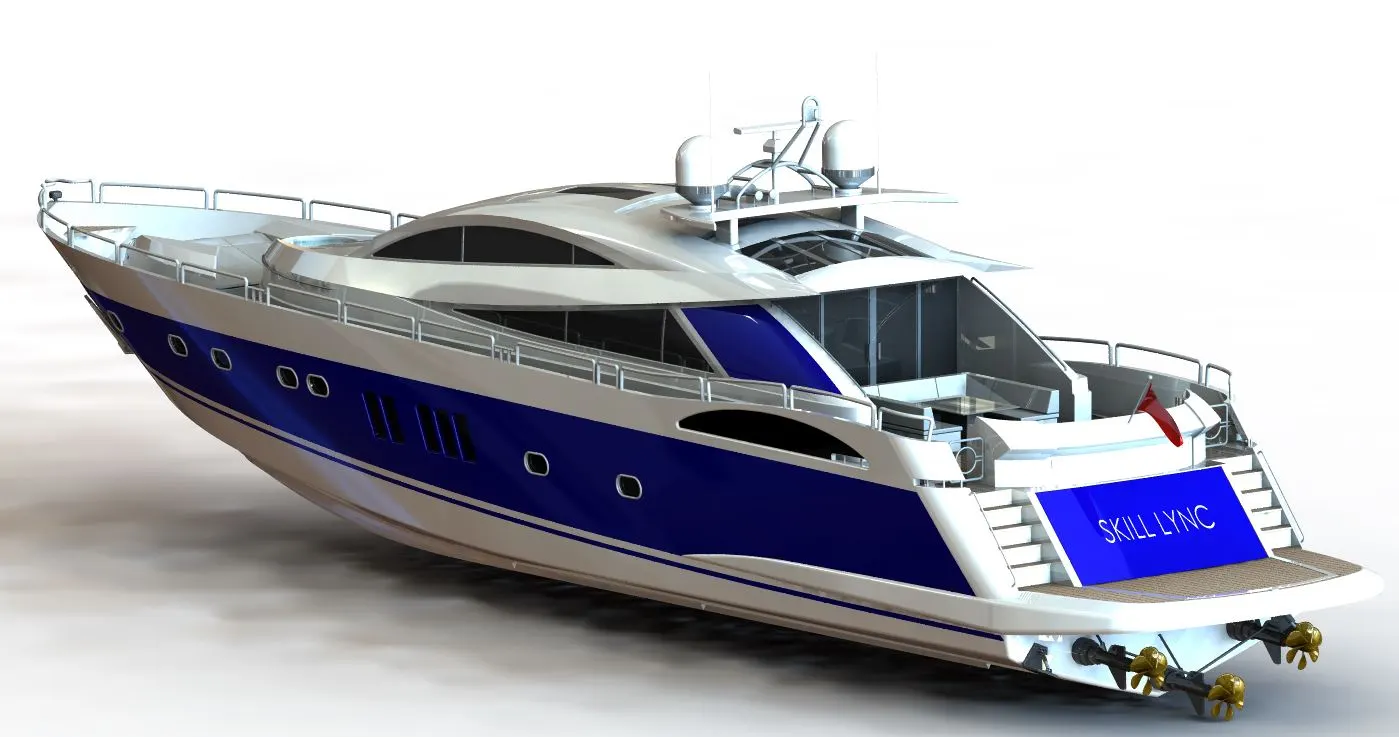
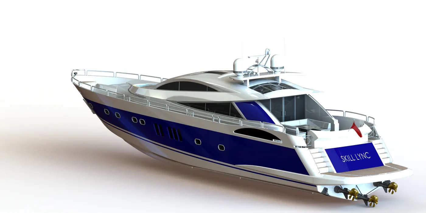
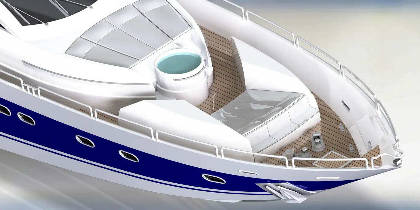
Rendering of Yacht Assembly:-
Conclusion:-
1. The parts of the Predator Yacht are sketched and modeled in Solidworks.
2. The parts are inserted into the assembly environment and applying proper mates yacht is assembled.
3. The realistic image was rendered by using photo view 360.