Assembly of Yacht
Objective:
The Objective of this project is to re-create the American Classic with the use of technology at our disposal.
We would be creating all the individual parts like wheels, chassis, tank etc with the use of SOLIDWORKS.
Post creation of parts they would be assembled with the use of Assembly feature within SOLIDWORKS.
Finally we would be using PHOTVIEW360 to apply proper aesthetics like Lights, Camera, Background environment, Backdrop lights, Shadows etc. in accordance to real world scenarios.
Requirement:
We need Solidworks version 2015 and above for the creation and assembly of individual parts for the Chopper.
We would require PhotoView360 or Solidworks Visualize interface for the rendering process.
Method Followed:
- Parts Creation:
SOLIDWORKS interface offers us a variety of features in order to create the desired model. Below mentioned is a short description of the tools used to create parts for the American Chopper under the tab SKETCH.
- Line/Centre Line: As the name suggest we are able to create Lines using this tool both for creation of the model and creating references.
- Circle: We can create a circle with the use of a centre point/ radius or we can use the perimeter.
- Rectangle: We can create a rectangle with the use of different options corner rectangle, centre point rectangle, 3point corner rectangle, point centre rectangle and a parallelogram.
- Slots: We have different types of slots but in our model, there is straight slot, centre point straight slot, 3point arc slot and centre point arc slot. We only make use of straight slot.
- Arc: We use this tool quite often in our model creation. There is 3point arc, centre point arc and tangent arc.
- Spline: This is an important tool in our arsenal towards the model creation. We have made use of only spline however there also is equation driven spline and Style spline.
- Fillet: This is a tool heling us to smooth out edges/corners. We make use of fillet and Chamfer.
- Trim Entities: This tool helps us in the removal of any excess material. There is also an option to extend part to the next sketch.
- Convert Entities: The tool helps us to bring a sketch made on different plane into the current sketch. There is also an option to use intersection curve which is used for spherical/rolled models.
- Offset entities: The tool helps us to create the same sketch but at an offset from the diagram.
- Mirror: The tool helps us to copy the sketch along an axis.
- Linear/ Circular Pattern: The tool helps us to copy the diagram in a linear or circular fashion.
- Smart Dimension: We can define dimension of our diagram with the use of this tool.
- Add Relation: The tool helps us decide whether our sketch has been defined completely. A fully defined sketch is always best.
- Sketch Picture: We can bring in a picture for reference from Tool Sketch tools Sketch Picture.
- Block: This tool helps us define a sketch as a block and hence forth allow us to insert the same in different sketches.
The Other feature used is the Features/Surface Tab. This where we define the thickness of the design to generate the model.
- Extrude Boss: We can provide instant thickness to any contour sketched by us.
- Revolve Boss: We can provide thickness to our sketch by rotating it about an axis.
- Swept Boss: We can provide thickness to our sketch by sweeping contour along a path. There is an option to use guide curves to achieve better results.
- Lofted Boss: We can provide thickness to our sketch by joining two contours along a path and define guide curves for creating our model.
- Boundary Boss: We can provide thickness to our sketch by defining the boundary of contour to be joined.
- Extruded Cut: Removes the material of the contour.
- Revolved cut: Removes the material by revolving the sketch about the axis.
- Swept Cut: Removes material by sweeping across the path.
- Lofted Cut: Removes the material along the two sketches along a path.
- Fillet/Chamfer: We can round the edges of our model with the use of this feature. We have the option to create a new edge.
- Pattern: We can remove or add material for our model by selecting the feature, body in a linear fashion or in circular fashion.
- Shell: We can provide thickness to the model created in order for it to be hollow.
- Split: The construction of a line can removes the material with the use of split by selecting the surface to remove. We can also use it to remove the coincident/ merged point of two or more surfaces and remove the unwanted part.
- Combine: We can merge together two or more single parts into one with the use of this feature.
- Dome: This feature allows us to create a lift a surface into a dome fashion.
- Reference: This helps us to create Plane and Axis with the use of reference points/plane/surface/vertex.
- Curves: We use this feature to create 3d curves by the use of two or more reference sketches. We can combine two or more curves with the use of composite curve. We can split a face into parts with the use of split line.
- Knit Surface: This is only in surface to join two or more surface together into one.
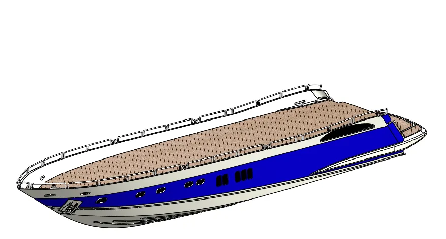
Hull
It is a watertight enclosure of the ship which means the base structure of the ship that product water not to allow inside the ship
the hull is designed a reference of blueprint
Command used to design
Sketch, Project curve, helix/spiral curve, sweep, boss & cut extrude, boss revolve, surface loft. Trim, surface fill, knit surface, reference plane, fillet, chamfer, Dome, linear pattern, mirror, split, combine, shell, offset surface
To apply appearance to the hull by applying Appearance (colours), Decals (picture)
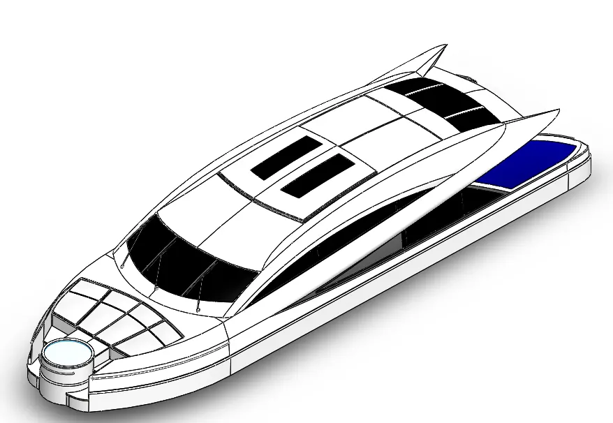
Superstructure
superstructure means to add construction to an already existing structure which means above the hull. In ships, this is the name given to the part of the ship that emerges from the deck
With the reference of the hull base surface & blueprint superstructure start design
Command used to design
Sketch, Project curve, helical curve, reference plane, sweep, extrude (surface, cut, Boss), revolve, loft (surface, Boss), Trim, surface fill, knit surface, ruled, fillet, chamfer, Dome, linear pattern, mirror, Delete Face, split line, combine, offset surface
To apply appearance to the superstructure by applying Appearance (colours), Decals (picture)
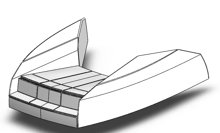
Seats
With the reference of the hull, surface & blueprint seats are design
Front seat
Command used to design
Sketch, plane, surface sweep, surface loft, extrude (surface, cut, Boss), knit, chamfer, fillet, Revolve (boss), trim surface, mirror, Dome
Middle seat
Command Used
Sketch, plane, extrude (Boss, cut), chamfer. Fillet, mirror
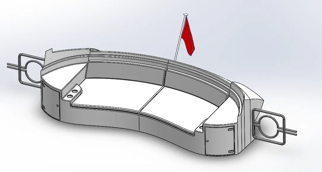
Rear seat
Command Used
Sketch, 3D sketch, plane, extrude (surface, Boss, cut), loft(surface), chamfer. Fillet, mirror, surface fill, surface offset, surface trim, Ruler
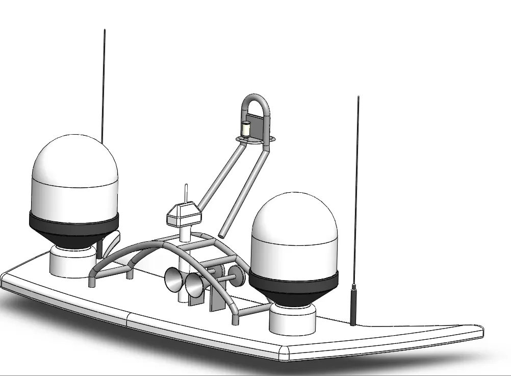
Radar mast
With the reference of superstructure surface & blueprint, Radar mast start design
They are electronic navigation instruments that use a rotating antenna (Radar)to sweep a narrow beam of microwaves around the water surface surrounding the ship to the horizon, detecting targets by microwaves reflected from them, generating a picture of the ship's surroundings on a display screen.
Command used to design
Sketch, reference plane, sweep (Boss), extrude (cut, Boss), revolve (Boss) fillet, chamfer, Dome, mirror, Delete Face
apply appearance to the Radar mast by applying Appearance (colours)
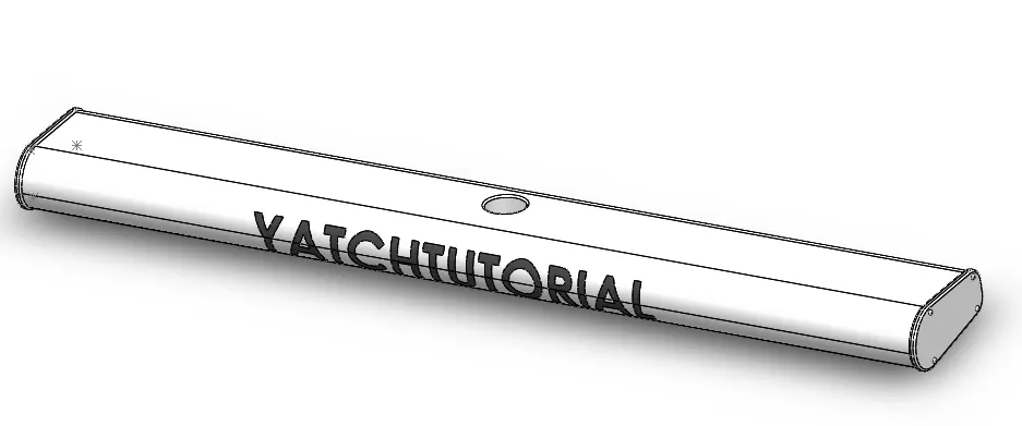
Radar
Command used to design
Sketch, extrude (cut, Boss), fillet, mirror, sketch pattern, the split line
apply appearance to the Radar by applying Appearance (colours)
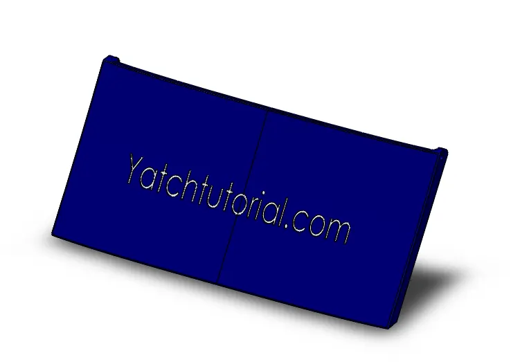
Garage door
From the reference of hull
Command used to design
Sketch, extrude cut, fillet, mirror. font
Propeller
Command used to design
Sketch, Revolve, extrude cut, fillet, circular patten, loft
Assembly
To constrain the part inappropriate position
Command used
Mate
Coincide
Distance
From the reference of the hull by default constrain to plain in Assembly from that superstructure, seats, for rear seatmate of hull top face and distance, radar which is created as default reference, radar as coincide with radar mast & coincide with radar top face, Garage door with plain of hull & coincide with the garage head holder.
Propeller is coincided with propeller & shaft coincide with the face.
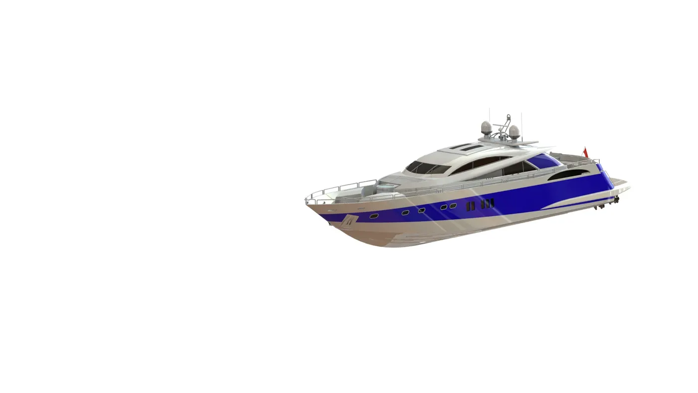
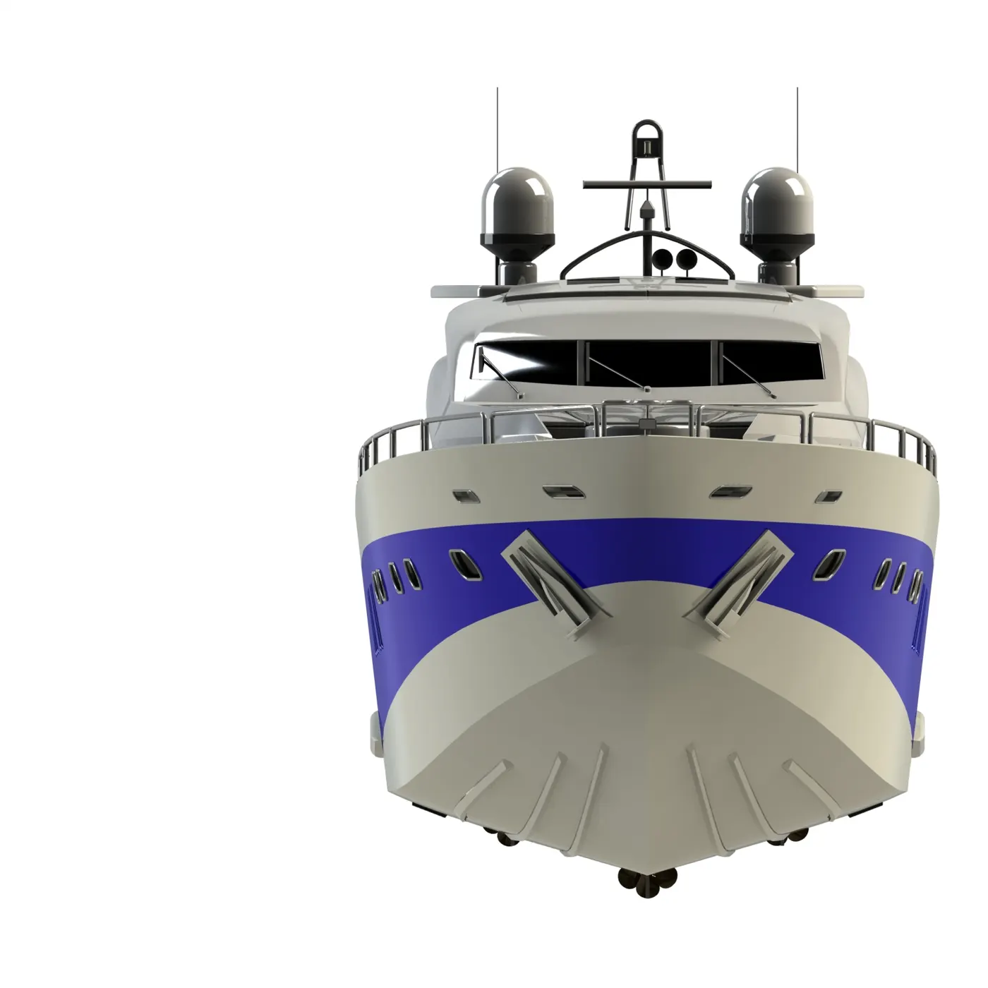
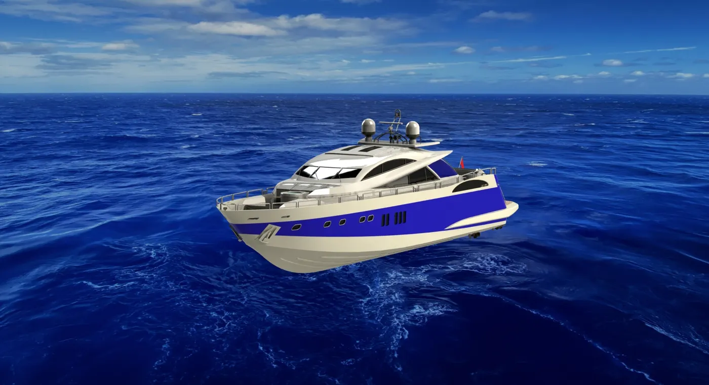
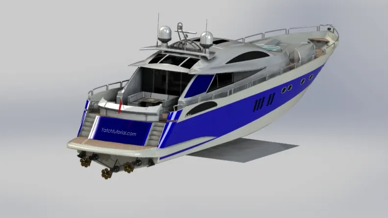
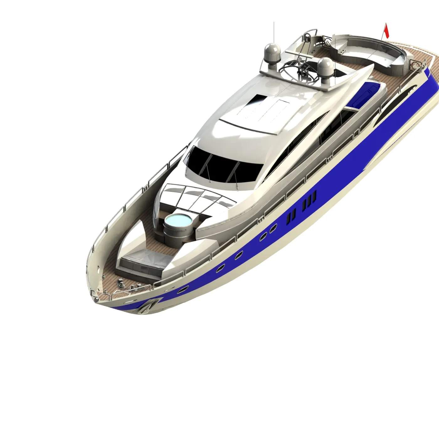
Conclusion:
At the end of Project each and every component designed individually in part file and assembled them to complete Yatch Design. Additional Appearances/setup like Decals, Scenes and Renders given to make it more realistic & Finally Rendered after placing designed Yatch in decent background Scenes.