Analysis & Design of RCC shear walls in the model using ETABS
AIM:
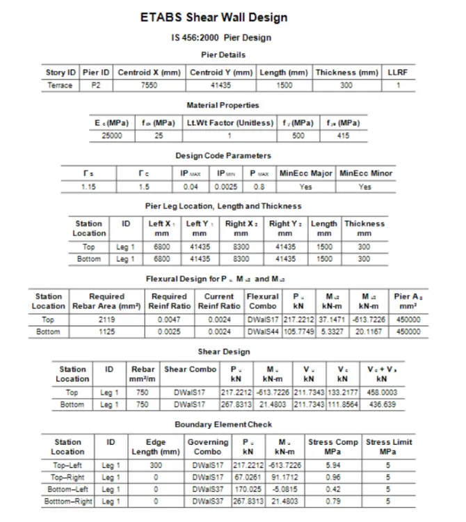
to take values from the design findings for the length of the boundary element, the longitudinal steel ratio, and the shear reinforcement ratio.
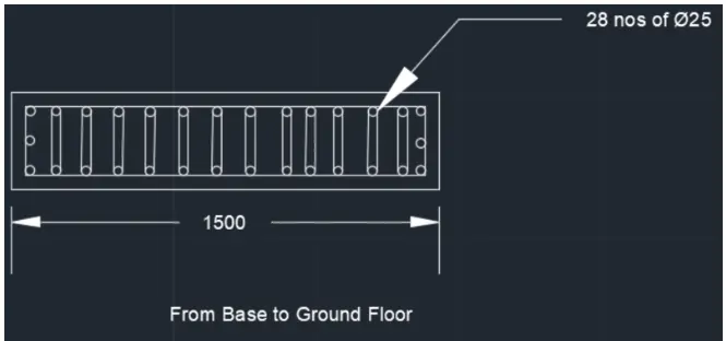
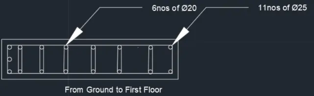
To provide the shear wall's cross sectional steel arrangement from the ground up to the terrace.
For this activity, AutoCAD software can be used, although it can also be drawn by hand.
to supply elevation drawings showing the shear wall's reinforcement features from the ground up to the terrace.
INTRODUCTION:
Shear walls are vertical components of the system that resists horizontal forces.
They are made to counteract a structure's exposure to lateral load.
Shear walls will be strong and stiff enough to withstand horizontal forces provided they are correctly designed and built.
High-rise structures subjected to lateral wind and seismic stresses require the use of shear walls more than other structures.
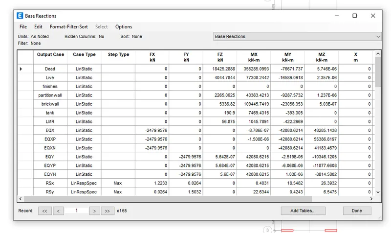
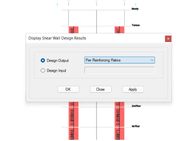
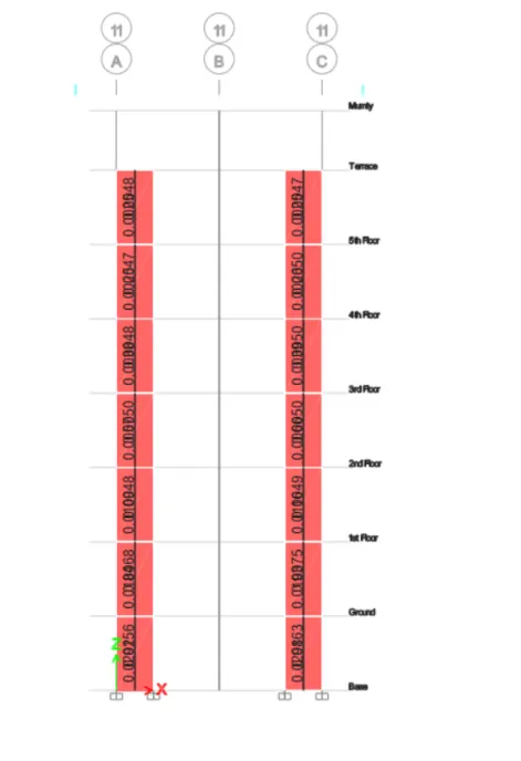
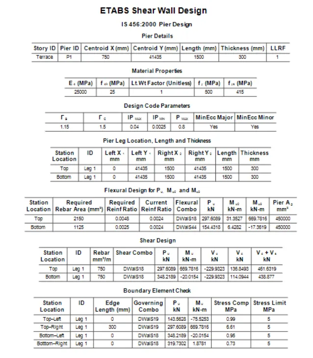
RESULT:
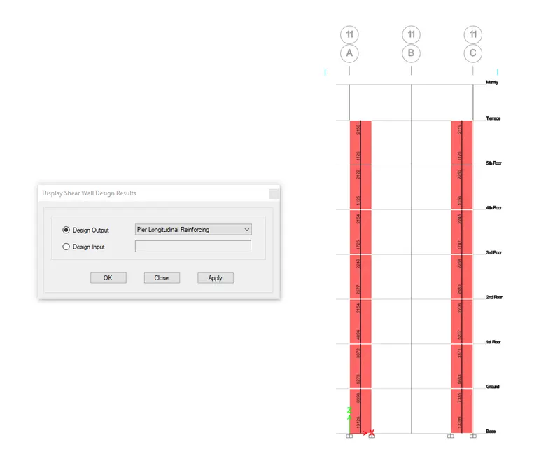
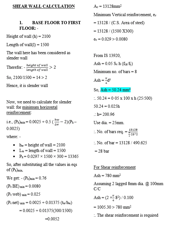
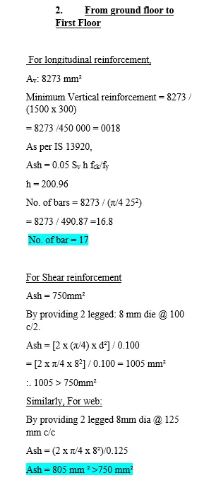
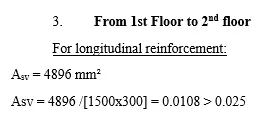
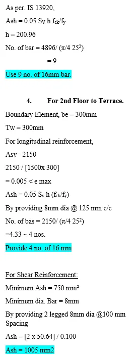
provided the shear reinforcement ratio, boundary element length, and longitudinal steel ratio values that were retrieved from the design results.
In accordance with the requirements of IS 13920 - 2016, provided cross-sectional steel arrangement of the shear wall from its base up to terrace.
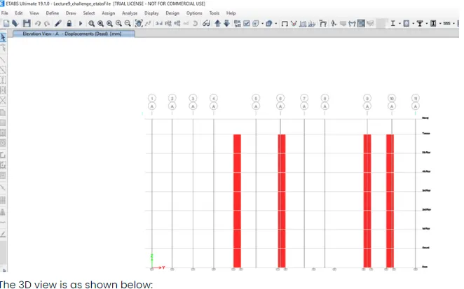
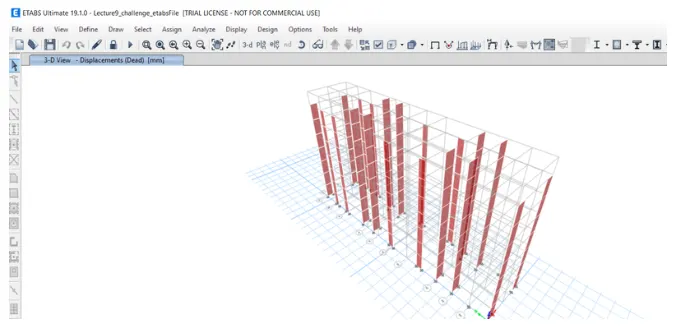
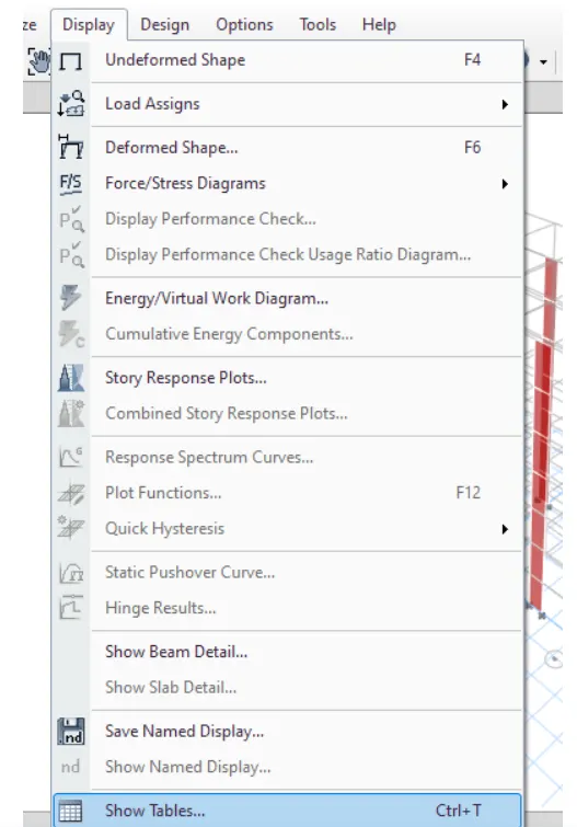
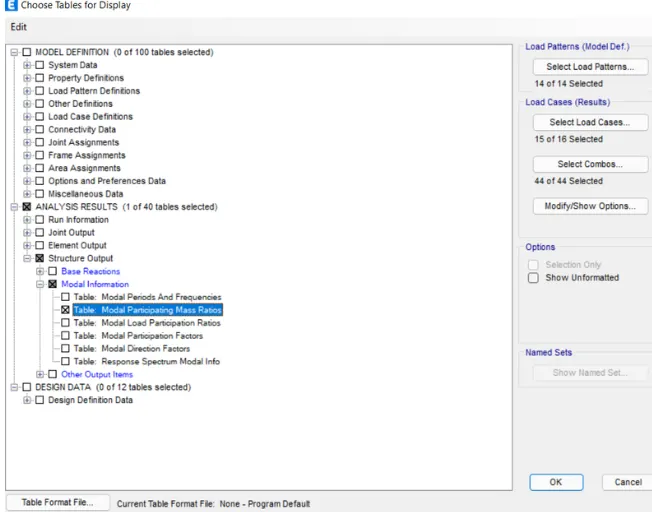
used the design outcomes from the ETABS file to create the RCC shear wall.
Provide elevation drawings showing the shear wall's reinforcement elements from the base to the terrace.