Analysis & Design of RCC shear walls in the model using ETABS
Aim of the challenge is to analyse, design and reinforcement detailing of the shear wall located at grid point A-11. Extracting the values of longitudinal steel ratio, boundary element legths, shear reinforcing ratio and providing cross sectional data of the given shear wall as per IS 456, Is 1893,IS 13920 etc. are also the aim of this challenge.
Storey data of the given building is shown below
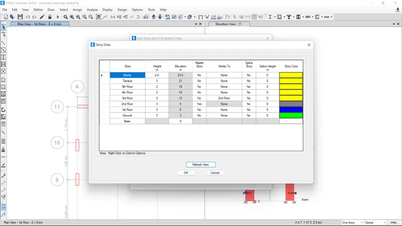
image of shear wall located at grid pont A11 (300x1500 )mm in size
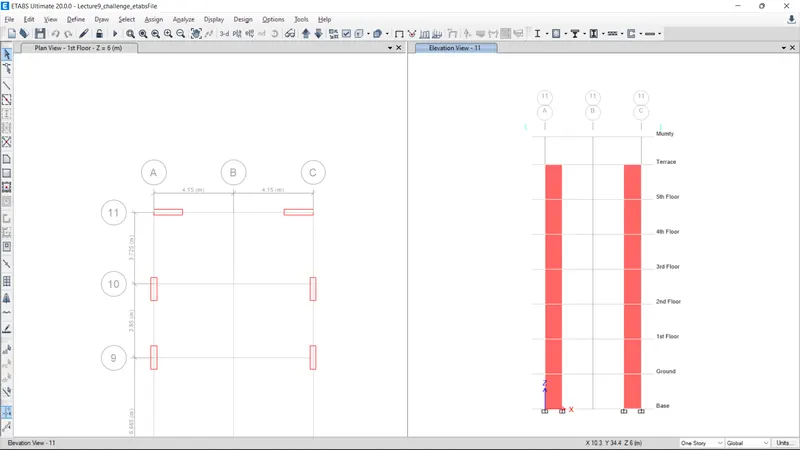
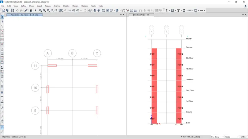
Pier label was assigned correctly
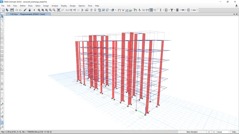
Analyisis got completed. Deformed shape of the model is provided below
Shear wall design completed
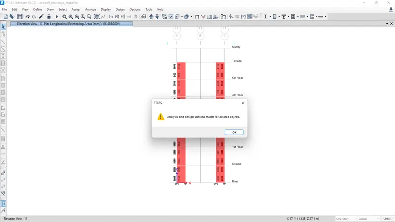
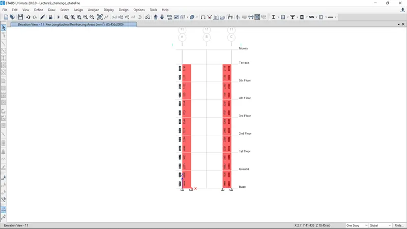
Pier Longitudinal rebar data
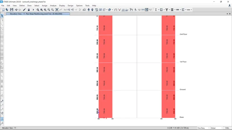
Pier shear reinforcement (Horizontal reinforcement) data
Pier edge (Boundary zone width)
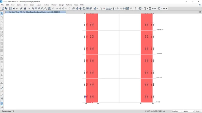
NA represented in figure indicating there is no need of boundary elements to carry lateral shear.
From the analysis result we can fix left side boundary width as 600mm and right hand side width of boundary element as 450mm
For any RCC member we have to provide minimum reinforcement for the respective members irrespective of the design values due to the following reasons
a) Minimum reinforcements for shrinkage and temperature
b) Ultimate limit state design rebar
d) Minimum reinforcement for ductility requirements
Among the above three values greatest value should be taken for shear wall reinforcement detailing
classification of shear walls as per IS 13920 Cl 10.1.4
Walls can be defined slender when hw/lw > 2
Here hw/Lw = 21000/1500 = 14 > 2 hence selected wall is a Slender wall
Minimum net vertical reinforcement as per Table 1(iii)

(ρ v,net) = 0.0025 + 0.01375 (300/1500) = 0.00525
area of vertical reinforcement = 0.00525 x 300 x 1500 = 2363 mm2 (Reinforcement ratio x top area)
Minimum Vertical reinforcement provided for Boundary element lengths
a) Left boundary with boundaray element width 600 mm
(ρ v,be)min = 0.0080 (As per Table 1(iii) of Is 13920
Area of steel required = reinforcement ratio x top area
0.0080 x 600 x 300 = 1440 mm2
a) Right boundary with boundaray element width 450 mm
(ρ v,be)min = 0.0080 (As per Table 1(iii) of Is 13920
Area of steel required = reinforcement ratio x top area
0.0080 x 450 x 300 = 1080 mm2
Minimum Horizontal bars for shear wall required as per Is 13920 - 2016 Table 1 (iii)

ρh is the Horizontal reinforcement ratio arrived from the ETABS result
We obtained a value for ρh as 7.5 cm2/m /300x1000 = 750 mm2/m /300x1000 = 0.0025
Now
(ρh)min = 0.0025 + 0.5(21000/1500 - 2) (0.0025-0.0025)
= 0.0025
Area Required = 0.0025 x 300 x 1000 (reinforcement ratio x thickness of wall x unit height) = 750mm2/m
Maximum dia of vertical bars can be used in Shear walls as per IS 13920-2016 Cl.10.1.8

Hence
1/10 x 300 = 30 mm
Provide 25 mm dia vertical reinforcements
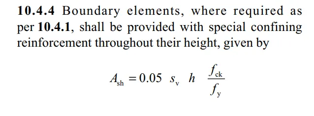
Like in RC columns we have to provide Confining reinforcements for RC elements as per IS 13920-2016 Cl 10.4.4
And spacing of confinemet reinforcement is not more than
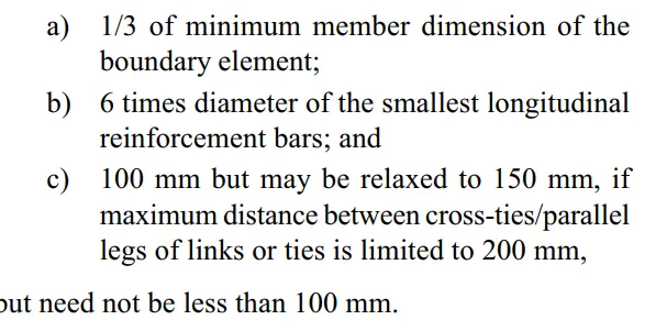
Spacing a) 1/3 x 300 = 100 mm
b) 6 x 25mm = 150 mm
c) if spacing b/w vertical bars is less than 200mm maximum spacing can be increased to 150mm
Here spacing b/w vertical bars is less than 200 mm so we cal provide a maximum spacing of 150 mm for the confining (shear reinforcement )for entire height for the wall.
Area of confining reinforcement as per Cl 10.4.4
Ash = 0.05 Sv x h x (fck/fy)
= 0.05 x 150 x 1000 (unit height) x(25/415)
= 432 mm2
Provide 28 Nos of 25 mm dia bars for longitudinal reinforcements, Horizontal(Shear reinforcement) as 8mm dia single ring at a spacing of 250mm dia c/c throughout and 8 mm dia additional ring for boundary element confinement at left and right boundary element width at a spacing of 150mm c/c.