Air Standard Cycle using MATLAB
AIM :To Visualize P-V diagram of Otto Cycle and to calculate thermal efficiency of heat engine using MATLAB.
OTTO CYCLE :
An Otto cycle is an idealized thermodynamic cycle that describes the functioning of a typical spark ignition piston engine. It is the thermodynamic cycle most commonly found in automobile engines.
The Otto cycle is a description of what happens to a mass of gas as it is subjected to changes of pressure, temperature, volume, addition of heat, and removal of heat. The mass of gas that is subjected to those changes is called the system. The system, in this case, is defined to be the fluid (gas) within the cylinder. By describing the changes that take place within the system, it will also describe in inverse, the system's effect on the environment. In the case of the Otto cycle, the effect will be to produce enough net work from the system so as to propel an automobile and its occupants in the environment.
The Otto cycle is constructed from:
- Top and bottom of the loop: a pair of quasi-parallel and isentropic processes (frictionless, adiabatic reversible).
- Left and right sides of the loop: a pair of parallel isochoric processes (constant volume).
The isentropic process of compression or expansion implies that there will be no inefficiency (loss of mechanical energy), and there be no transfer of heat into or out of the system during that process. The cylinder and piston are assumed to be impermeable to heat during that time. Work is performed on the system during the lower isentropic compression process. Heat flows into the Otto cycle through the left pressurizing process and some of it flows back out through the right depressurizing process. The summation of the work added to the system plus the heat added minus the heat removed yields the net mechanical work generated by the system.
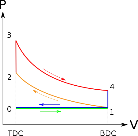
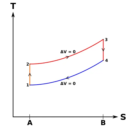
PROCESS :
- Process 0–1 a mass of air is drawn into piston/cylinder arrangement at constant pressure.
- Process 1–2 is an adiabatic (isentropic) compression of the charge as the piston moves from bottom dead center (BDC) to top dead center (TDC).
- Process 2–3 is a constant-volume heat transfer to the working gas from an external source while the piston is at top dead center. This process is intended to represent the ignition of the fuel-air mixture and the subsequent rapid burning.
- Process 3–4 is an adiabatic (isentropic) expansion (power stroke).
- Process 4–1 completes the cycle by a constant-volume process in which heat is rejected from the air while the piston is at bottom dead center.
- Process 1–0 the mass of air is released to the atmosphere in a constant pressure process.
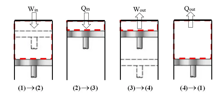
Process 1-2 Compression stroke
Piston moves from crank end (BDC, bottom dead centre and maximum volume) to cylinder head end (TDC, top dead centre and minimum volume) as the working gas with initial state 1 is compressed isentropically to state point 2, through compression ratio (V1/V2). Mechanically this is the isentropic compression of the air/fuel mixture in the cylinder, also known as the compression stroke. This isentropic process assumes that no mechanical energy is lost due to friction and no heat is transferred to or from the gas, hence the process is reversible.
Process 2-3 ignition phase
The piston is momentarily at rest at TDC. During this instant, which is known as the ignition phase, the air/fuel mixture remains in a small volume at the top of the compression stroke. Heat is added to the working fluid by the combustion of the injected fuel, with the volume essentially being held constant.
Process 3-4 expansion stroke
The increased high pressure exerts a force on the piston and pushes it towards the BDC. Expansion of working fluid takes place isentropically and work is done by the system on the piston. Mechanically this is the expansion of the hot gaseous mixture in the cylinder known as expansion stroke.
Process 4-1 heat rejection
The piston is momentarily at rest at BDC. The working gas pressure drops instantaneously from point 4 to point 1 during a constant volume process as heat is removed to an idealized external sink that is brought into contact with the cylinder head.
FORMULAS :
1.Swept Volume = The volume swept by the piston during its motion is known as swept volume.It is given by
`V_s=pi/4 times d^2 times l`
where,
d= diameter or bore of piston
l= stroke or height of piston
2.Clearance Volume= The volume which is left between piston and top dead center of cylinder during combustion or exhaust stroke is called as clearance volume.
`V_c= V_s/(r_c-1)`
where,
`r_c`= Compression ratio of cylinder
3. Total Volume = The sum of swept volume and clearance volume is total volume.
`V_t=V_s+V_c`
4. Adiabatic Process= An adiabatic process is a type of thermodynamic process which occurs without transferring heat or mass between the system and its surroundings.
`PV^gamma=Constant`
where,
P=Pressure of system
V= Volume of system
`gamma`=Ratio of specific heats of fluid
5.Universal gas law stating `(PV)/T=Constant`
6.Trace volume inside the engine combustion chamber is given by
`V/V_c=1+1/2(r_c-1)[R+1-cos(theta)-(R^2-sin^2(theta))^(1/2)]`
where,
V=Volume inside cylinder when piston is at an angle `theta`
R=Ratio of length of connecting rod to crank pin radius(`a`)
a=crank pin radius =stroke length/2= `l/2`
7.Thermal efficiency of Otto cycle is given by
`eta=1-1/r_c^(gamma-1)`
MATLAB program :
clear all
close all
clc
%input
gamma= 1.4
t3=2300                    %temperature at state point 3 in Kelvin
%state variables at state point 1
p1=101325                  %pressure at state point 1 in Pascals
t1=500                     %temperature at state point 1 in Kelvin

%Engine geometric parameters
bore=0.1;
stroke=0.1;
con_rod=0.15;
cr=12;
%swept volume ,clearance volume
v_swept=(pi/4)*bore^2*stroke;
v_clearance= v_swept/(cr-1);

%volume at state point 1 and 2
v1=v_swept+v_clearance
v2=v_clearance
%state variable at state point 2
% p2v2^gamma = p1v1^gamma | p2=p1*(v1/v2)^gamma
%p2=p1*cr^gamma
p2=p1*cr^gamma;
%temperature at statepoint 2
%p1v1/t1=p2v2/t2 | t2 =p2v2t1/p1v1
t2=p2*v2*t1/(p1*v1);
constant_c=p1*v1^gamma;
V_compression=engine_kinematics(bore,stroke,con_rod,cr,180,0);
P_compression=constant_c./(V_compression).^gamma

%state variable at state point 3
v3=v2
%p3v3/t3 = p2v2/t2 | p3= p2t3/t2
p3=p2*t3/t2;
constant_c=p3*v3^gamma;
V_expansion=engine_kinematics(bore,stroke,con_rod,cr,0,180);
P_expansion=constant_c./(V_expansion).^gamma


%state variable at state point 4
v4=v1
%p4v4^gamma=p3v3^gamma
p4=p3*(v3/v4)^gamma

%Thermal_efficiency of engine
Thermal_efficiency=1-1/cr^(gamma-1)
%plotting
figure(1)
hold on
plot(v1,p1,'*','color','r')
plot(V_compression,P_compression)
plot(v2,p2,'*','color','r')
plot(v3,p3,'*','color','r')
plot(V_expansion,P_expansion)
plot(v4,p4,'*','color','r')
plot([v2 v3],[p2 p3],'color','b')
plot([v4 v1],[p4 p1],'color','b')
xlabel('volume')
ylabel('pressure')
title('OTTO CYCLE')
Explanation of code :
1.Starting the program with clear all,close all,clc commands
clear all command clears the data stored in workspace .
close all command is used to close previous plots and figures.
clc command is used to clear the command window
2.Assuming the input variables and declaring values to the input variables.
3.Engine geometric parameters are entered .These include bore,stroke,connecting rod length and compression ratio of engine.
4.Swept volume and clearance volume are claculated using the formula mentioned above.
5.The state variables v1,v2,p2,t2,v3,p3,v4,p4 are calculated using the above mentioned formulas.
6.A seperate code is written in a new script and the function defined is used to achieve a set of solutions for every value of crank angle.
function[V]= engine_kinematics(bore,stroke,con_rod,cr,start_crank,end_crank)

a=stroke/2 %crank pin radius;
R=con_rod/a;

v_s=(pi/4)*bore^2*stroke;
v_c=v_s/(cr-1);

theta=linspace(start_crank,end_crank,100);

term1=0.5*(cr-1);
term2=R+1-cosd(theta);
term3=(R^2-sind(theta).^2).^0.5;
V=(1+term1*(term2-term3)).*v_c;

end
7.In the above script,function syntax is used which declares a function named "engine_kinematics" that accepts inputs in "bore,stroke,connecting rod length,compression ratio,start crank angle and end crank angle".
8.Formula required for the calculation of `R`,crank pin radius (a) are entered.
9.The crank angle values are calculated for 100 values between start angle and final angle.
10.To obtain the volume curve, the volume trace inside a cylinder is calculated when the piston is at an angle `theta`.
11.The function called in the code and V_compression,P_compression,V_expansion,P_expansion are calculated.
12.Thermal efficiency of engine is calculated using the above mentioned formula.
13.Finally all state variables are plotted along with PV curves and the PV cycle is thus obtained.
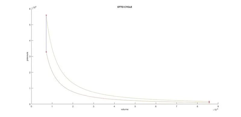
Plot of P-V diagram :
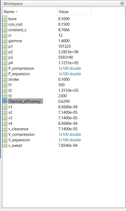
Values from work space :
Reference:
https://en.wikipedia.org/wiki/Otto_cycle
RESULTS:
- The P-V diagram for all the process has been plotted.
- The Thermal efficiency of engine is `62.99 %`.Thermal effieciency mainly depends upon compression ratio of engine and the type of fluid.So it can be concluded that engines with high compression ration will have high thermal efficiency.