Ahmed Body Challenge
Ahmed Body:
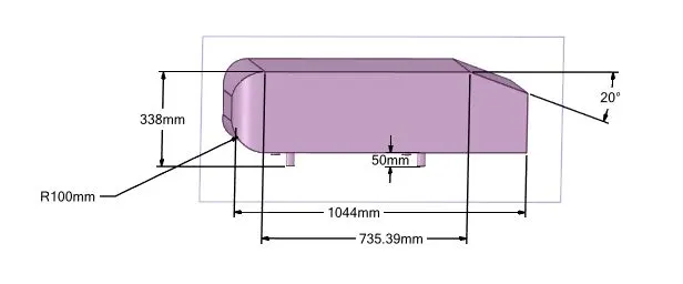
Ahmed Body is a simplified car geometry which helps in carrying out experiments to understand the flow around an automobile vehicle. In industry, it is widely used as a benchmark to validate the simulation tools. Examining flow around an Ahmed Body helps in understanding how aerodynamic drag affects the fuel efficiency of a car. As the shape of the Ahmed body is made generic in nature, it becomes simple enough to model while retaining car-like features.
Negative pressure in wake region and the significance of point of separation:
When a body moves through a fluid with some velocity fluid exerts a pressure on the body as drag.
A viscous fluid will produce a prominent drag force on the body. At the same time if the speed of the body is sufficiently high, then also the drag increases. Usually, much like friction, drag is an unwanted effect in external flows, so we try to minimize this effect. The total aerodynamic drag depends on two components friction drag and pressure drag.
Friction Drag: The friction drag is a component of wall shear force in the direction of flow, and invariantly it depends on the orientation of the body as well as the wall shear stress. Due to a strong dependence on viscosity, the friction drag increases as viscosity increases.
However, as Reynold's Number is inversely proportional to viscosity the contribution of friction drag to total drag is very negligible at higher Reynold's Number and in such cases the total-drag is mostly due to pressure drag only.
Pressure Drag: The pressure drag is proportional to the frontal area and the difference between pressure between the front and rear of the body. Hence, this value is dominant for the blunt shape bodies while it is almost negligible for the thin flat plates parallel to the fluid flow and streamlined bodies. The pressure drag attains high value when the fluid velocity (Reynolds Number) is high, as a result of this, the fluid is unable to follow the curvature of the body and thus separates from the body which creates a low-pressure zone at the back of the body.
In internal flows, the entire flow field is dominated by viscous effects, while in external flow the viscous effects are confined to a portion of the flow field such as boundary layers and wake region.
Separation of the fluid layer from the body surface takes places because of excessive momentum loss near the boundary while trying to move against the increasing pressure. After a certain point on the body, the pressure gradient can be positive or adverse.
- If the pressure force in the direction of flow decreases gradually, then the pressure gradient is said to be favourable or positive gradient. Hence, with the assistance of this positive pressure gradient and force due to acceleration, the flow continues and does not separate. The combined force can overcome the opposing viscous force.
- However, if the pressure gradient is adverse then the fluid flow is opposed by pressure forces itself in addition to viscous forces. Hence, the fluid particles have to resist these combined forces to maintain the flow. As and when the fluid layer fails to resist these forces it separates from the wall and are driven in the upstream direction. The far-field external stream pushes back these separated layers and as a result, a wake region is formed behind the body.
Mathematically, the point of separation is a sweet spot between forward and reverse flow and can be expressed as
`frac{du}{dy}_(y=0) = 0`
After separating from the boundary and as adverse pressure exists, a recirculating flow is also developed in the wake region.
The flow separation is analogous to moving vehicle at high speeds around corners. A safety measure to avoid being thrown off the road while driving along a road is to slow down around the curved corners. Absence of such precautions causes severe accidents as car detaches or separates from the road surface.
A similar process occurs in case of fluid flowing over curved surfaces or blunt bodies at higher velocities. At high speeds, the inability of fluid to remain attached to the body surface causes the phenomena of flow separation.
Several methods like streamlining the body shape and injecting fluid synthetically near the actual point of separation are used wherever the drag coefficient or drag force has to be reduced. However, care must be taken as excessive streamlining of the body can very well decrease the pressure drag but eventually, it will increase the friction drag. Hence, a balance must be created while designing the body.
To understand above flow processes a standard external flow around an Ahmed body is studied.
Solving & modelling approach:
Geometry:
- Body Splitting: Since the Ahmed body is symmetrical along the length, using the Split option in SpaceClaim the body is halved. This process helps in saving computational efforts as well as reduces simulation time.
- Primary enclosure: Using the bounding box method Ahmed body was enclosed. This process was performed in the baseline mesh scenario to verify whether an approximate solution is being simulated.
- Secondary Enclosure: Similar to the primary enclosure box, a secondary enclosure box is generated. This secondary box is treated as a region of refinement.
Meshing:
- Named Selection: Before generating mesh named selection was created on components of geometry.
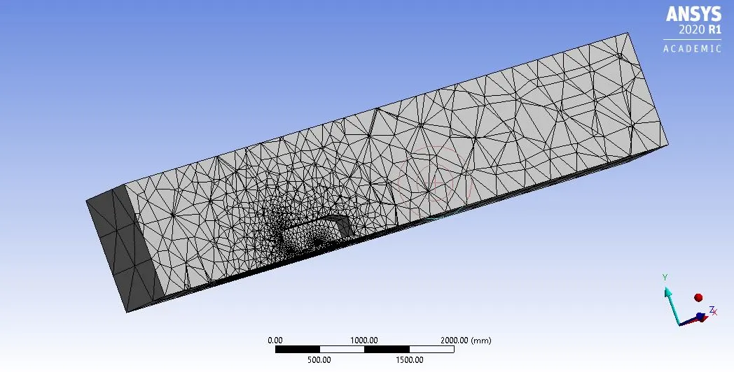
- Base Mesh: In the case of the base mesh only primary enclosure box has meshed with Element Size = 413.6mm (Default Value)
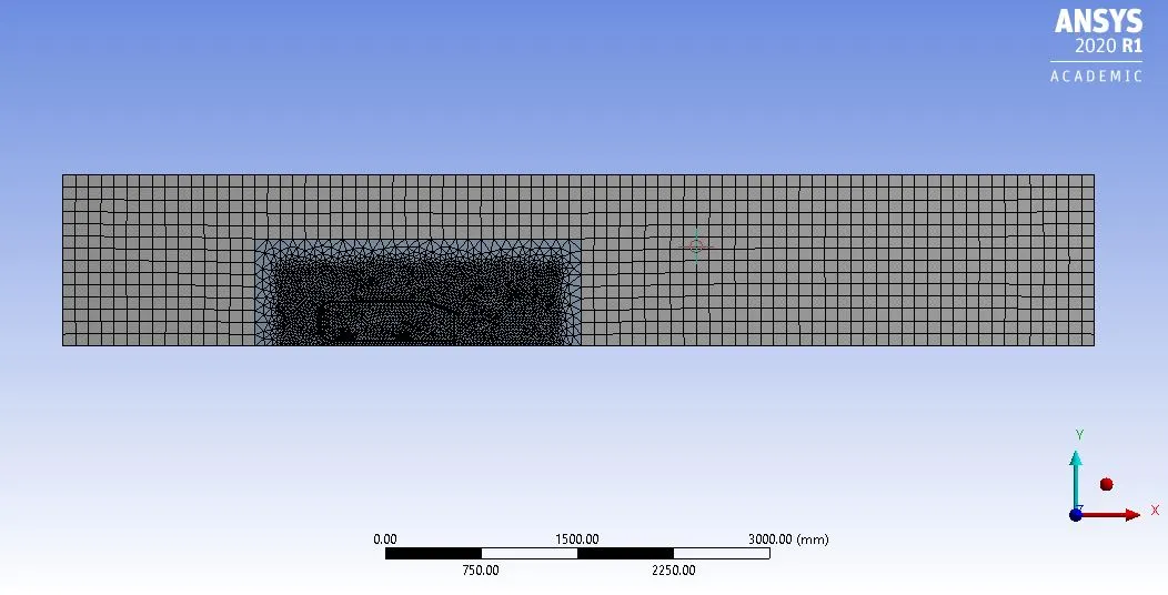
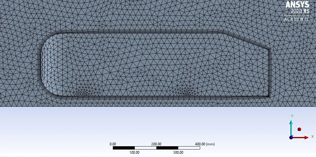
- Refined Mesh: In this case, the process of mesh creation was performed on both primary enclosure with Element Size = 100mm and region of refinement (secondary enclosure box) Element Size = 50mm.
- Face Sizing: In the refined mesh scenario Face Sizing of 5mm is applied to the support of Ahmed body.
- Inflation Layer: An inflation layer of a total thickness of 16.15mm was applied around the edge of the Ahmed body surface. This total thickness was distributed among 5 layers which grew at a rate of 1.2. As a result, the final refined mesh became a body-fitted mesh i.e. the mesh that closely follows the shape of the body.
Base Mesh
Refined Mesh with region of refinement and inflation layers
Solver and Solution Configuration:
For both base mesh and refined mesh following solver settings were used:
- Inlet Velocity = 25 `frac{m}{s}`
- The density of fluid = 1.225 `frac{kg}{m^3}`
- Visosity = 1.79E-05 `frac{kg}{m.s}`
- Characteristic Length = 1.044 m
- Reynold's Number = 1.79E+06
- Solver = Pressure based steady-state
- Turbulence model = k-epsilon
- Using standard correlations of Skin friction coefficient and wall shear stress corresponding values were calculated.
- Assuming a target y+ of 150 first layer thickness was calculated and subsequently, the total thickness of the boundary layer was also calculated.
- The total thickness for Refined Mesh = 16.15 mm
Results and Conclusion:
Results from Baseline mesh scenario
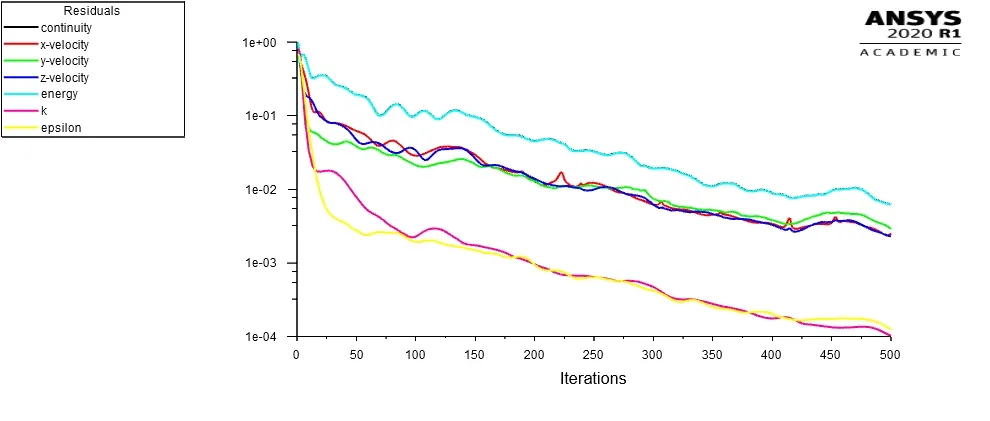
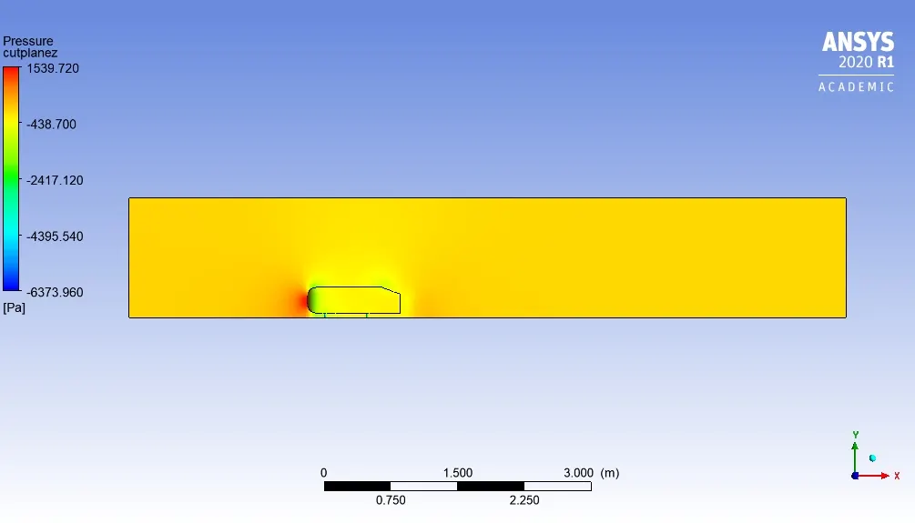
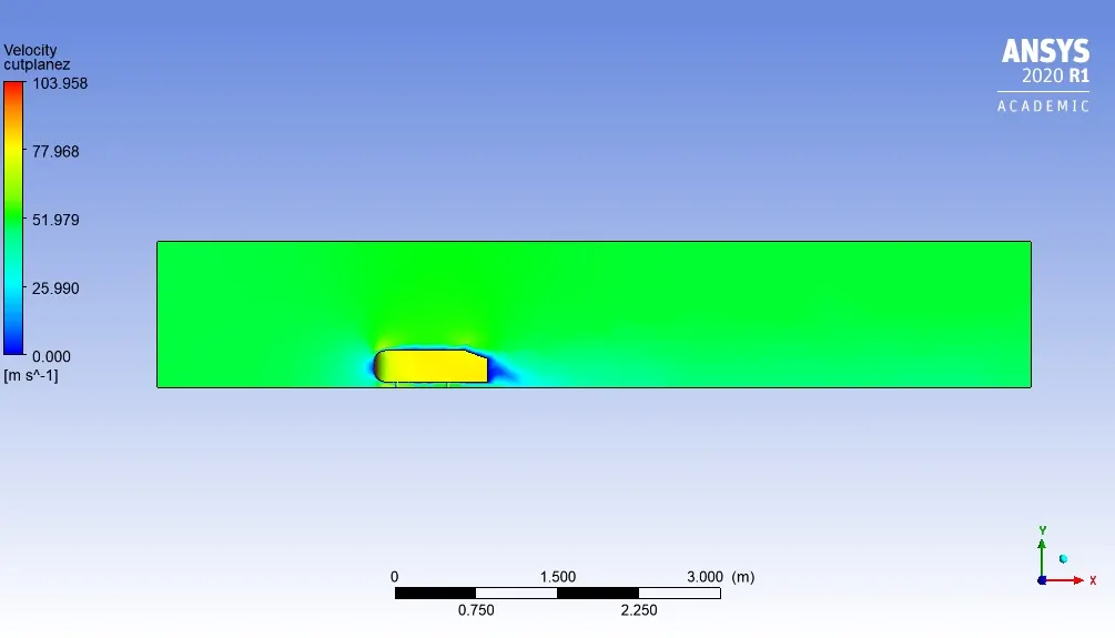
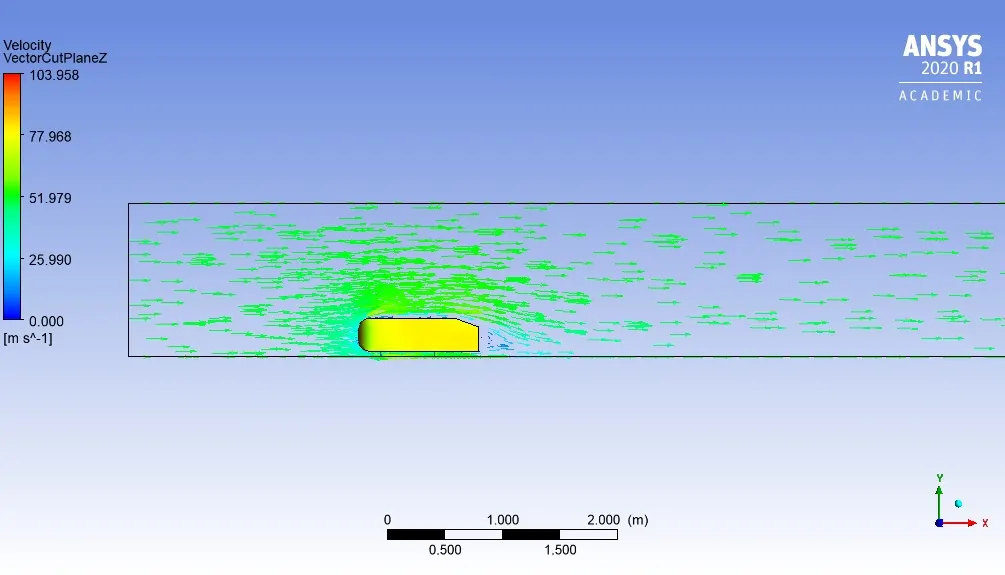
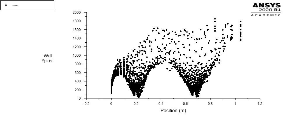
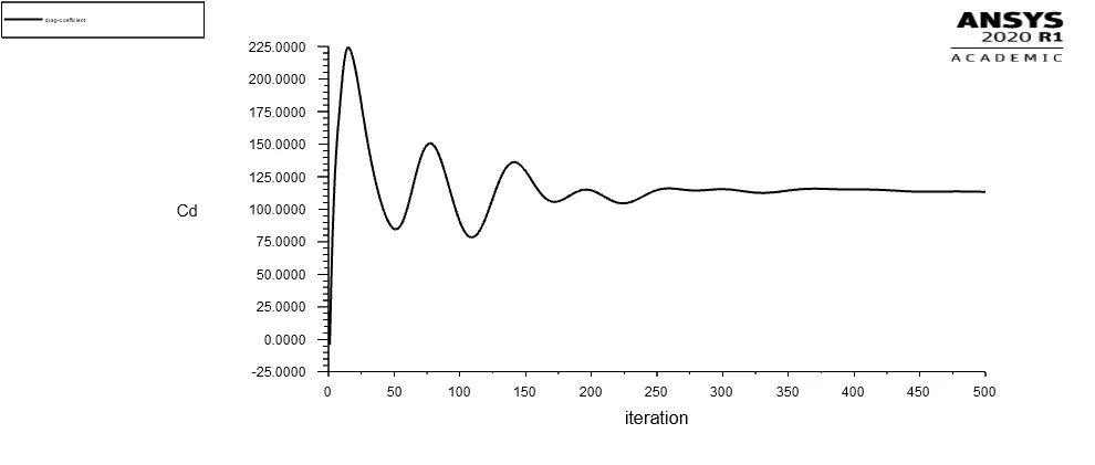
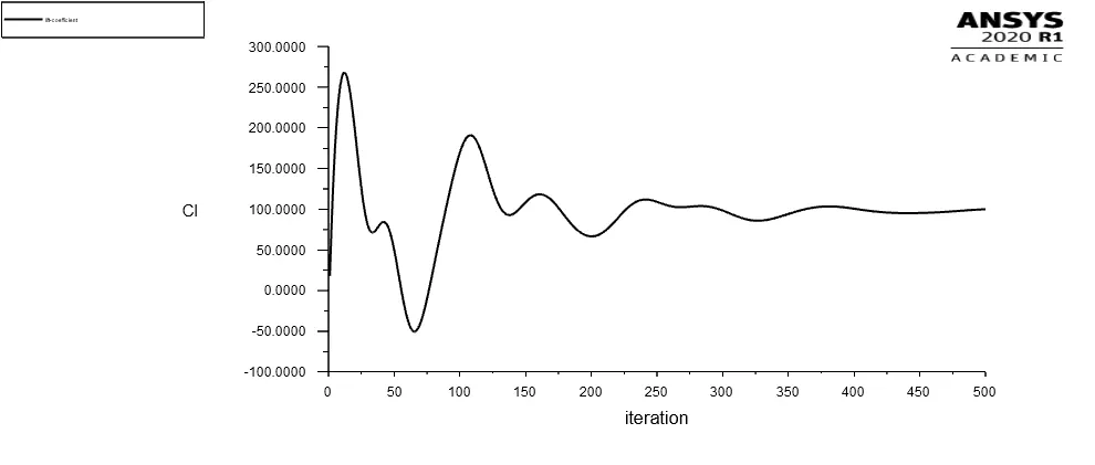
- The residual plot for 500 iterations indicates that the solution has not converged. However, drag and lift coefficient plots indicates otherwise. The pressure and velocity contour plots indicate that the flow has not fully developed.
- The pressure contour plot rightly displays a high-pressure stagnation point at the front portion of the Ahmed body.
- However, in this case, the wake region was not prominently observed, as shown in both velocity contour and velocity vector plots.
- The wall y+ value plot is misleading as the valid range for the k-epsilon turbulence model is 30-300. This is observed because no inflation layer is applied to the baseline mesh scenario. As a result, the fluid flow around the body has not been captured properly.
- The lift and drag coefficient values also do not fall in a valid range that has been experimentally observed. Hence, the setup needs more refinement.
Results from Refined mesh scenario
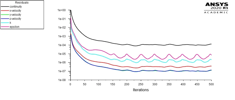
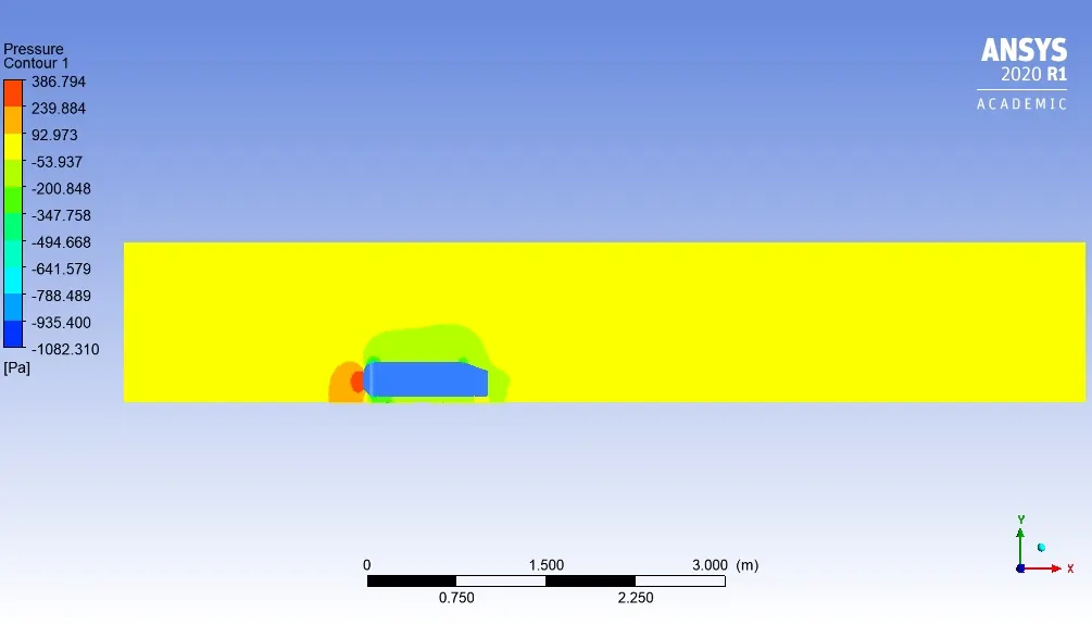
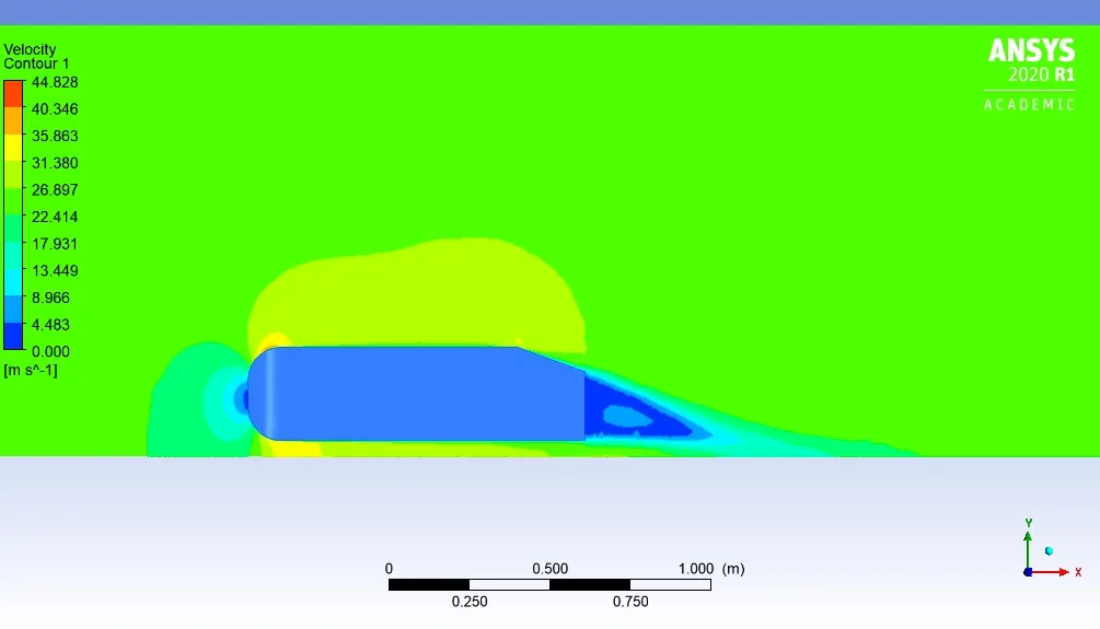
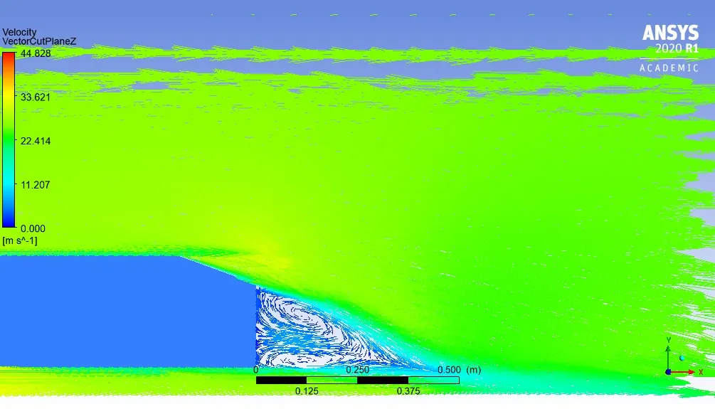
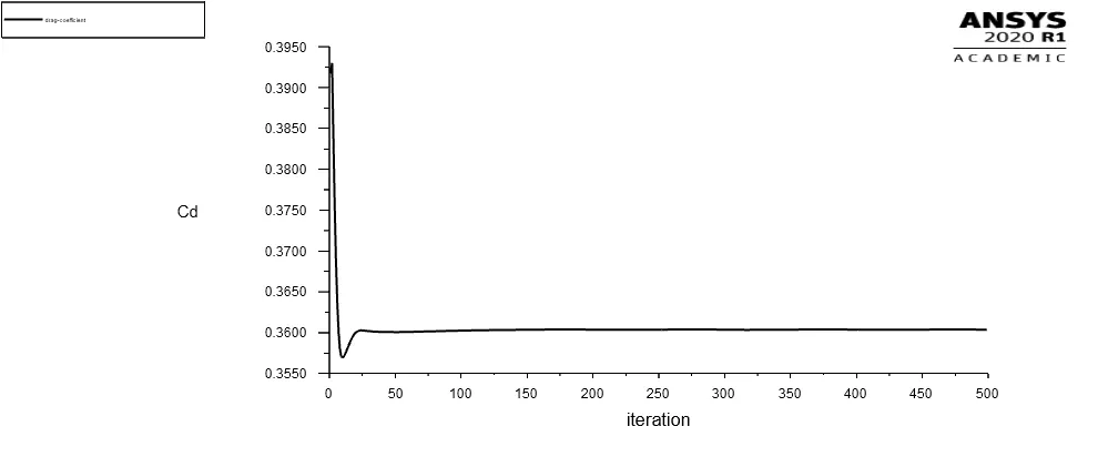
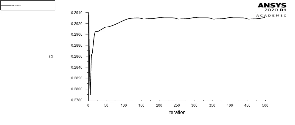
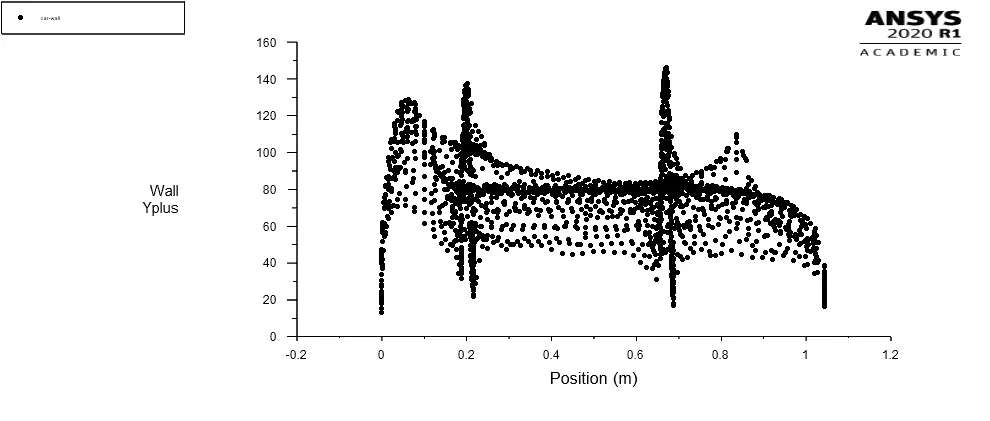
In the case of the refined mesh scenario, both y+ value plot and residual plot indicates that the solution has converged adequately and y+ values lie in the valid range for the k-epsilon turbulence model range.
- As seen in the velocity vector plot and contour plot, recirculation and backflow in the wake region is present in this case.
- The recirculation also falls within the defined boundaries of region of refinement. Hence, the dimensions of region of refinement are valid in this case.
- The average drag coefficient value in the refined mesh case comes out to 0.36 as opposed to 0.33 observed in the original experiment carried out by Ahmed.
- The slant angle considered in this case was 20 degree. The slant angle plays an important role in point and separation and formation of wake region behind the body. Varying this angle can produce effects of varying intensities behind the body, which consequently effects the drag coefficient and drag force acting on the body`.^[1]`
- Car motorsport racers often take advantage of the wake region of car running ahead of them. As the car running behind has to overcome a lesser drag force as compared to the car running in front. This helps the car to gain speed drastically.
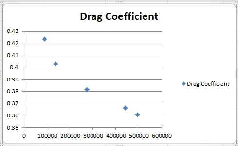
To check whether the solution has achieved grid independence, a grid dependence test was also performed.
- From the test, it can be observed that as the mesh becomes finer the error in drag coefficient value decreases. A coarse mesh having 88817 elements has 27% error, while a finer mesh with 0.495 million cells the error reduces to 9%.
- Within, two design points i.e. point A with mesh elements = 495065 (error rate = 9%) and point B with mesh elements = 442004(error rate = 10.9%). The change in error rate is approximately 2%. The case could be refined further, but because of computational constraints, the solution is assumed to have been independent of the grid points. The simulation performed is on an ANSYS Academic Licence, the number of elements cannot exceed beyond 0.5 million. Hence, the refinement of the solution is until these constrained limits only.
| Design Points | Mesh Element Size [mm] | Mesh Max Size [mm] | Body Sizing Element Size [mm] | Face Sizing Element Size [mm] | Mesh Number of Layers | Mesh Maximum Thickness [mm] | Mesh Elements | drag-coefficient-op | lift-coefficient-op |
| A | 100 | 100 | 24 | 5 | 5 | 16.15 | 495065 | 0.36036475 | 0.29308509 |
| B | 100 | 100 | 25 | 5 | 5 | 16.15 | 442004 | 0.36604894 | 0.28935033 |
| C | 100 | 100 | 30 | 5 | 5 | 16.15 | 274039 | 0.38138529 | 0.28990391 |
| D | 100 | 100 | 40 | 5 | 5 | 16.15 | 138703 | 0.4026582 | 0.29436225 |
| E | 100 | 100 | 50 | 5 | 5 | 16.15 | 88817 | 0.42334022 | 0.28025028 |
References:
[1] Meile, Walter & Brenn, Günter & Reppenhagen, Aaron & Lechner, Bernhard & Fuchs, Anton & Akademia Baru, Penerbit. (2011). Experiments and numerical simulations on the aerodynamics of the Ahmed body. CFD Letters. 3.
Link to Ansys Files: https://drive.google.com/file/d/1hb8fHkmkdAXjG8TG0b-iDkim5mLsx7b4/view?usp=sharing