Ahmed Body Challenge
- Introduction
The aim of this challenge is to simulate the flow over an Ahmed body. Separation flow, the wake formation and the drag / lift coefficients need to be calculated. At the same time, a grid independency test needs to be performed.
Automotive industry is interested in the aerodynamics of the vehicles because its shape has an impact on its stability, fuel consumption, maximum speed and passenger comfort. So, the study of flow domain around the vehicle is of high importance on handling the car performance, especially on minimizing its drag resistance.
Ahmed Body is a great concept which helps both the engineers and the researchers to understand the turbulent flow around a typical car bluff body. It consists of a round leading edge, a rectangular box and a moveable slant plane at the back of the body. The box connects the frond and the rear part. The rear part is a movable geometry and is used in order to investigate the separated flow and the wake formation in different angles of the slant pane.
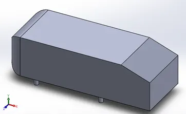
The Ahmed Body is generic model which is commonly test in wind tunnel, and it’s the base line for industry. Having a great data base of experimental data, it is very easy to validate a numerical model against to these. As a result, new designs can be explored, and their aerodynamic properties can be accurately predicted. This is the reason why Ahmed Body is so essential.
- Geometry
The given geometry is imported to the SpaceClaim. Initially, the geometry is enclosed in a box in order to create a computational domain, outside of the body. In the fluent mesher, the base line mesh is created. After setting up the physics and running the simulation, the results shows that the mesh is very coarse and mesh needs to be improved.
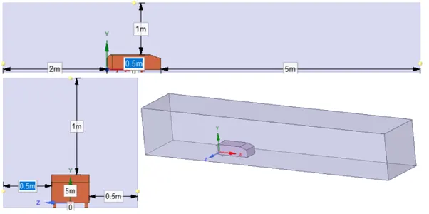
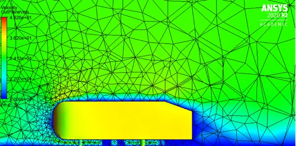
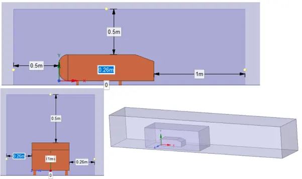
Due to these results, a second enclose box is created.
- Meshing generation
To create a fine mesh, the 5 methods are implemented. Multizone, Body Sizing, Face Sizing Edge Sizing and Inflation Layer.
It can be seen that there are to boxes inside its other. In the outer enclosure box, hexahedral mesh is chosen because it interacts with the inner enclosure box which consists of straight lines and it can perfectly adapt with it. To avoid creating a double mesh due to the two enclosure boxes, in the hexahedral mesh, Multizone option is selected. The mesh size for the outer enclosure box is 0.1m.
The second method which is applied is Body Sizing. This method is used in order to refine the mesh around the Ahmed Body. The type of the method which is selected is Element Size and its value is 0.05m. This means the element size of the inner enclosure mesh is 50mm.
Then, Face Sizing is applied on the surface of the Ahmed Body (15 Faces) and the element size is set 0.1m while Edge Sizing is implemented on the four pillars of the Ahmed Body and the element size is set 0.005m.
Last but most important method is the Inflation Layer around the wall (Ahmed Body). This is a body fit mesh which helps to capture gradients normal to the wall (like boundary layer). First layer thickness is chosen, however, in order to define the element size y+ needs to be chosen.
Reynolds number has to be calculated.
Re = (rho * V * L) / μ = (1.225 * 25 * 1.04) / 1.7894e-05 = 1779926.23 =1.77e06 > Re = 2e05
So, the flow can be considered as turbulent. First layer thickness can be calculated as follow:
Cf = 0.026 / Re ^ 1/7 = 3.327045e-03
τ_wall = Cf * rho * V^2 / 2 = 1.273634 kg/(m2 s2)
u_τ = sqrt(τ_wall / rho) = 1.01965 m/s
Having chosen y+ = 30, which means that the first layer needs to be in the viscous sublayer of the turbulent boundary layer. So,
y = (y+ * μ) / (u_τ * rho) = 4.2977e-04m
Total of 5 inflation layers are used with a growth rate of 1.2.
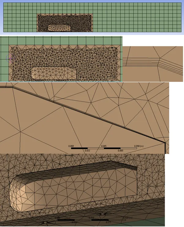
Before, case setting up starts, Inlet and Outlet faces has been named. Furthermore, the car surface is defined as a wall, with top, right and left surfaces to be assigned as symmetry. The bottom one is assigned as a wall.
For the grid independency, the next cases are simulated:
|
Outer enclosure |
Inner enclosure |
|
|
Case 1 |
0.2m |
0.06m |
|
Case 2 |
0.1m |
0.05m |
|
Case 3 |
0.09m |
0.04m |
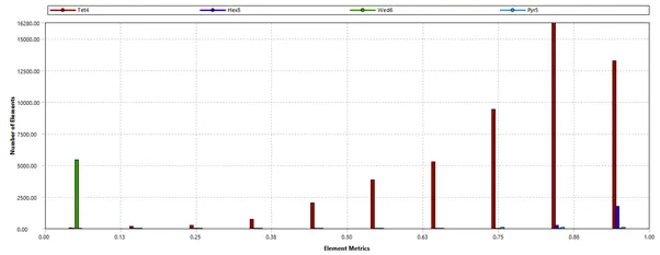
The following figure shows the tetra, hex, wedge and pyramid type of mesh element quality, under multizone mesh type. The mesh is quite good considering that the majority of the nodes have quality higher than 0.7.
- Case set-up
With regards to the case set up, the following figures shows all the individual settings.
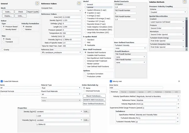
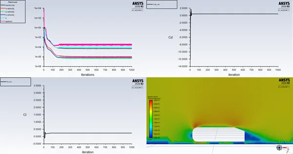
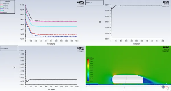
Hybrid initialization is used, and the simulation runs for 1000 iterations.
- Results
Case 1
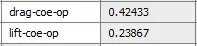
Case 2
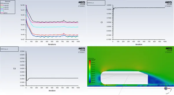
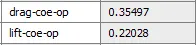
Case 3
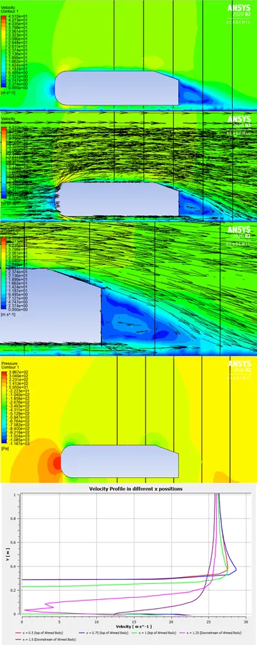
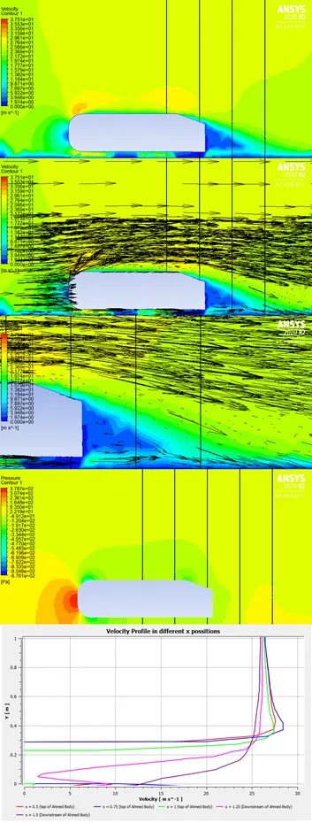
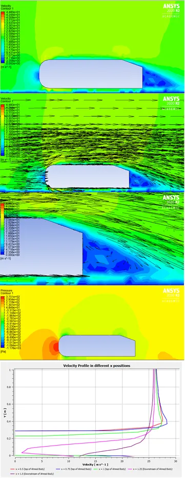
The above graphs show the flow separation at the rear part of the Ahmed body and the formation of a wake. The inclined surface of the Ahmed Body makes the flow to expand and separate. The flow separates due to adverse pressure gradient (dp/dx > 0) and the pressure is low and negative in some cases. This is because outlet pressure (which is set as guage pressure) is zero.
With regards to the separation point, the boundary layer detaches from the surface into the wake. This happens when the pressure gradient is positive, the velocity decreases until the flow stops and flows towards the opposite direction. After this, the wake forms and different vortices are generated. These vortices increase the drag of the body which is not desired. So, the delay of the separation point it is really important for the aerodynamic performance of the body.
- Conclusion
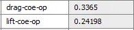
The simulation of the Ahmed Body is successful, with all the cases are to be converged. The wake is captured at every case, the grid independency test shows that at case 3 the drag coefficient matches the corresponding experimental value. Finally, the velocity and pressure contours show the flow domain around the Ahmed body and the line charts show the progression of the velocity profile from the top surface of the geometry to its wake.