Advanced Sheet Metal Design Using NX Cad Challenge_7_ Metal bracket-II
METAL BRACKET USING NX SHEET METAL APPLICATION:
OBJECTIVE:
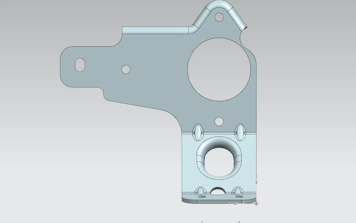
This is a project to learn the step by step procedure to create a Bracket with a gusset from the given 2D drawing.
INTRODUCTION:
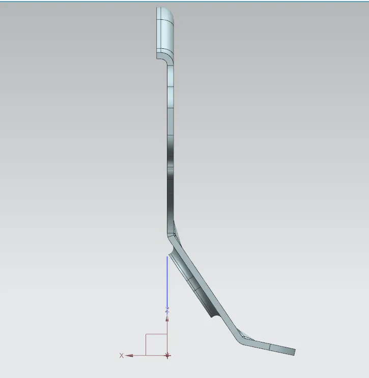
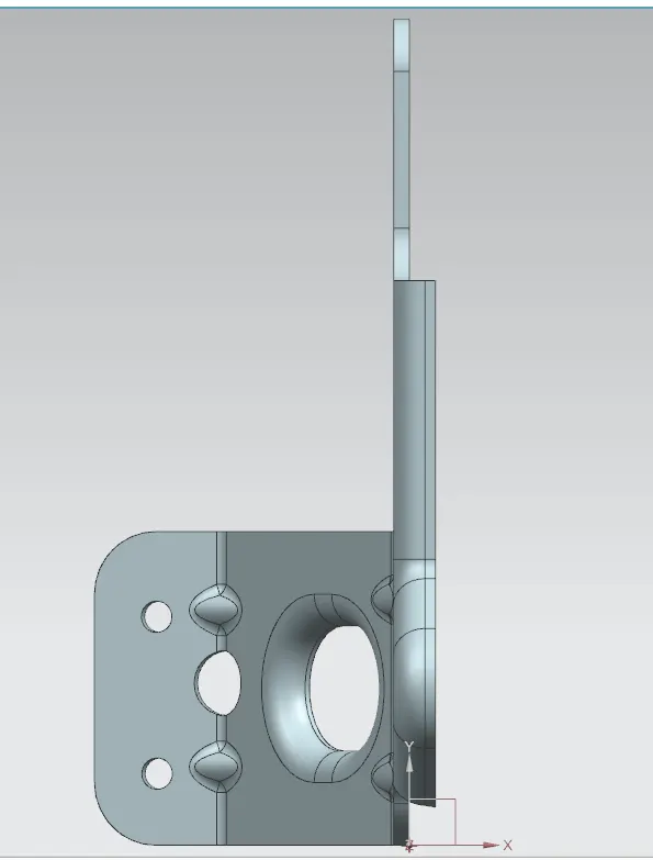
A bracket is an intermediate component for fixing one part to another. It is used to support the weight. Brackets vary widely in shape, here we are designing an L- shaped bracket.
DESIGN METHODOLOGY:
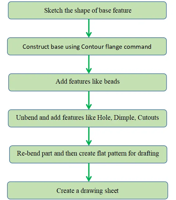
SHEET METAL MODELING:
Features and Tools:
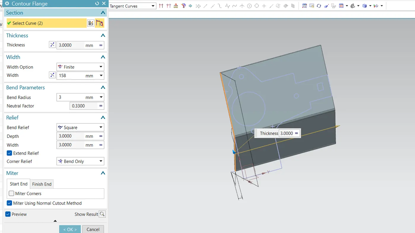
- Contour Flange: Creates a base feature by extruding the sketch along a vector or adding material by sweeping the sketch along an edge.
- Break Corners: This feature makes sharp edges smooth, round, or chamfer-shaped.
- Normal Cut-Out: It helps to cut material by projecting a sketch onto the model, cutting perpendicular to the face.
- Unbend: This feature helps to unbend the bent shapes to a flat pattern. In sheet metal the other features like cut-outs and holes needed to be created over the flat configuration. So that feature applied will be normal to a flat surface.
- Hole: Cut or remove the material with a thread pattern on it. For applying the hole feature there should be a specific point, which will be the center of the hole.
- Rebend: This command helps to rebend the previously unbent sheet and have a component in its original form.
- Advanced Flange: Add a flange along an edge using a bend angle or a reference face. The edge and reference face can be curved.
- Gusset: Creates a stiffening gusset on the part.
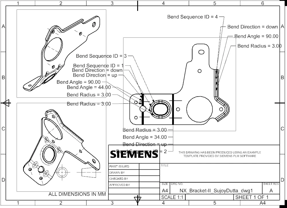
- Flat Pattern: It represents the whole component in 2D form. This flat pattern also shows entire features with dimensions.
- Drafting: Drafting is creating a technical drawing into a sheet, communicating about the dimensions and view of components. The draft helps the manufacturing and production department to know about the product design in a 2D format.
Procedure:
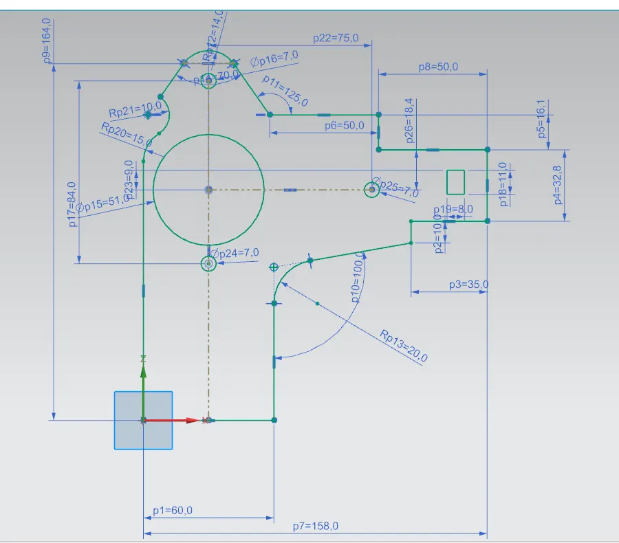
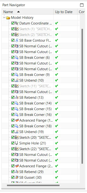
- Sketch the drawing for the contour flange on the XZ plane with a width of 158mm.
- Using normal cut-outs remove unwanted material by checking the 2D drawing.
- Use break corners to give a smooth curve to the corners according to the 2D drawing available.
- Unbend the model and cut out the shapes needed in the model.
- Rebend the model.
- Use an advanced flange and select the upper edge with a flange length of 5mm.
- Unbend the model again and give holes at the bottom of the part according to the drawing.
- Use a normal cut-out by sketching the shape between two bends. Then use advanced flange on the same sketch.
- Rebend the model and apply the gusset feature at the bend as shown in the drawing.
CONCLUSION:
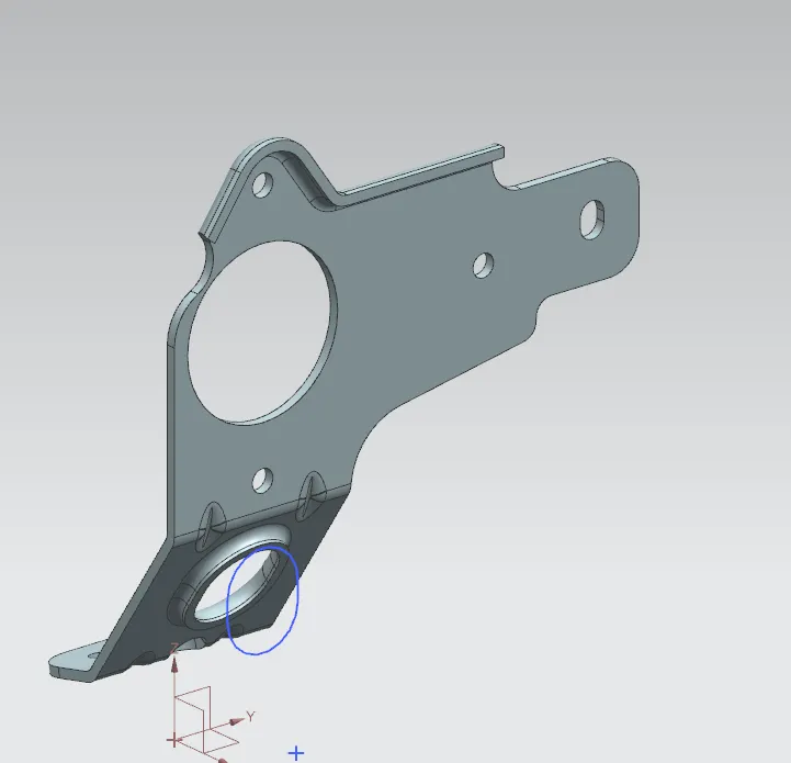
Sheet metal bracket is designed successfully using NX Cad application. From this project, we get to understand advanced flange and gusset features.