Advanced Sheet Metal Design Using NX Cad Challenge_7_ Metal bracket-II
Week 7- Challenge
DESIGNING A SHEET METAL BRACKET-II using NX-CAD
Introduction
Sheet metal is metal formed by an industrial process into thin, flat pieces. Sheet metal is one of the fundamental forms used in metalworking, and it can be cut and bent into a variety of shapes. Countless everyday objects are fabricated from sheet metal. Thicknesses can vary significantly; extremely thin sheets are considered foil or leaf, and pieces thicker than 6 mm (0.25 in) are considered plate steel or "structural steel".
NX sheet metal design software incorporates material and process information in sheet metal-specific modelling features: bends, flanges, tabs, cutouts, beads, dimples, louvers, corner and edge treatments, patterns and other formable features. We can also quickly convert solid models to sheet metal components, and create sheet metal parts that enclose other components.
With NX sheet metal CAD tools, we can apply standard values, such as material thicknesses and bend radii, based on industry or company best practices. With folding and unfolding capabilities, we can work with models at any stage of the fabrication process. NX sheet metal software creates accurate flat patterns for documentation and manufacturing.
- Powerful design capabilities: NX CAD offers a wide range of tools for creating and editing 3D models, including parametric modeling, surfacing, assembly modeling, and more.
- Advanced features: NX CAD boasts features like simulation, kinematics, and generative design, making it suitable for complex engineering challenges.
- Interoperability: NX CAD seamlessly integrates with other Siemens PLM software and can also import and export various CAD file formats.
- Various options: NX CAD is available in various configurations and deployment options, including on-premise, cloud-based, and subscription-based, to suit different needs and budgets.
Description
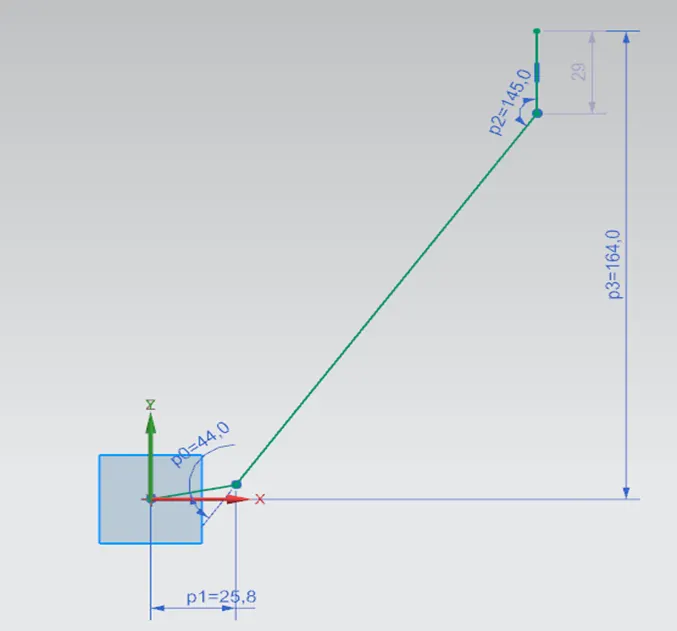
1. Skecth the side view of the Bracket in the XZ plane
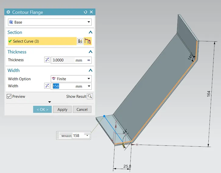
2. Create a Contour Flange for the body of the Bracket
- Contour Flange: Creates a base feature by extruding a sketch along a vector, or adds material by sweeping a sketch along an edge or chain of edges.
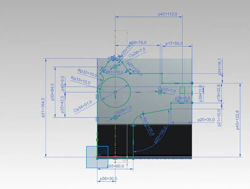
3. Sketch the Bracket profile in YZ Plane
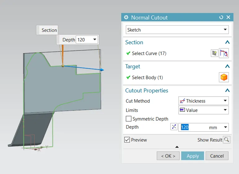
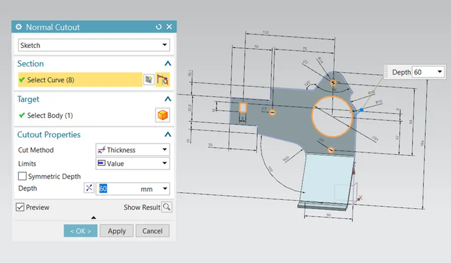
4. Use Normal Cutout to cut the Bracket into the required shape
- Normal Cut: Cuts material by projecting the sketch onto the model and then cutting perpendicular to the faces intersected by the projection.
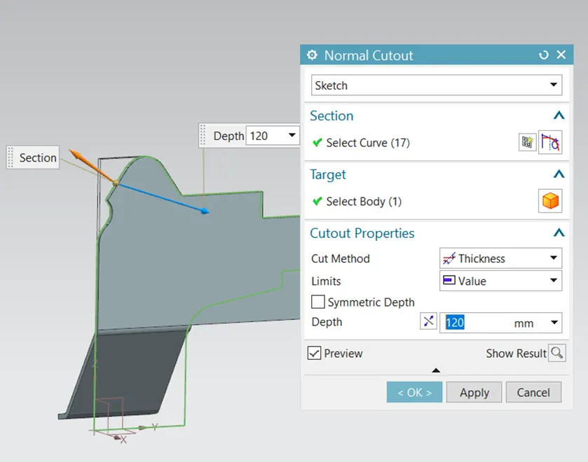
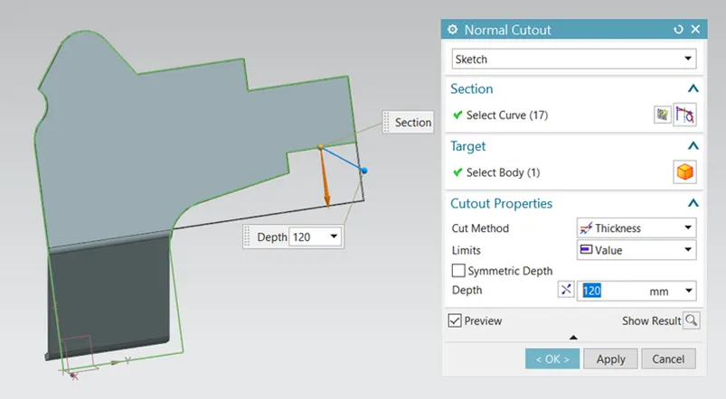
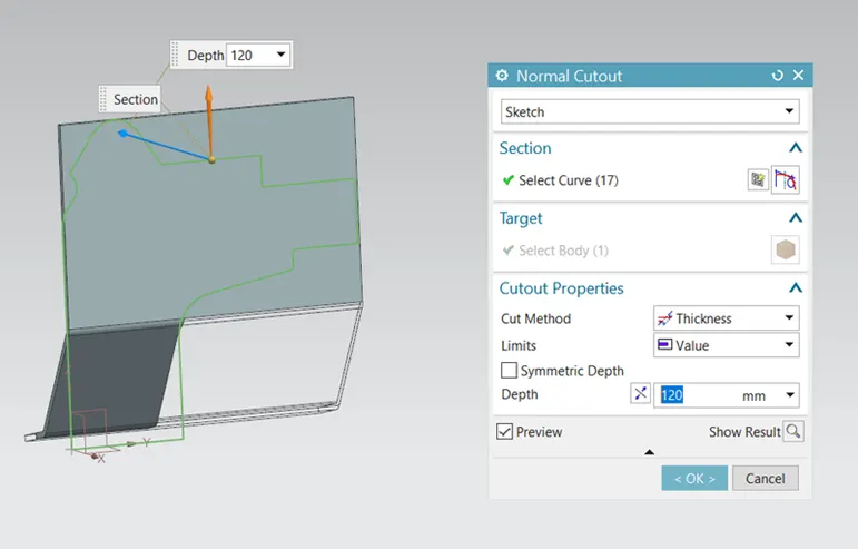
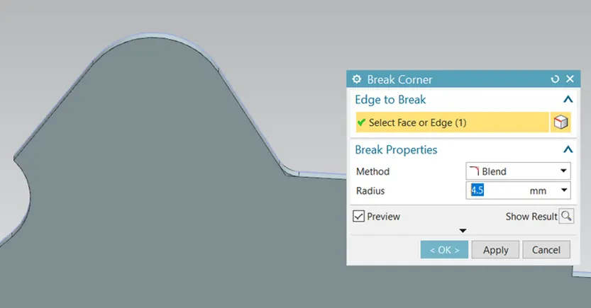
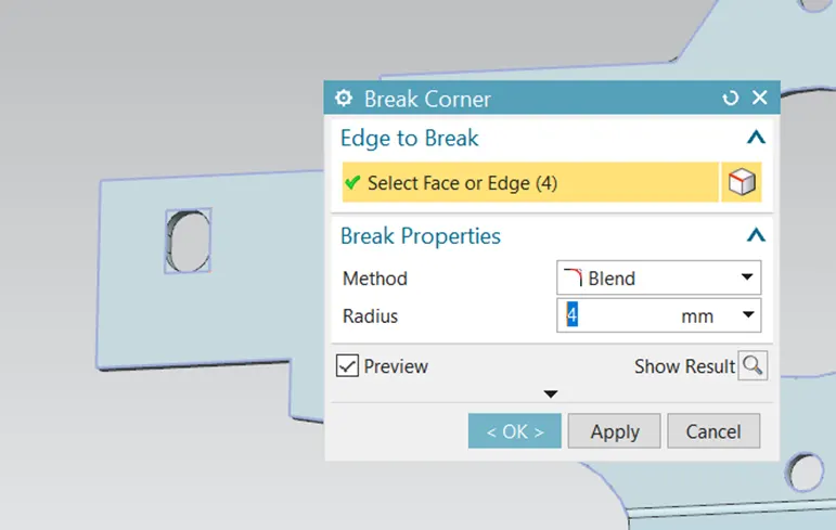
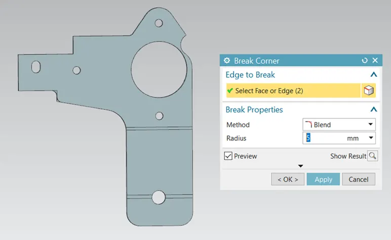
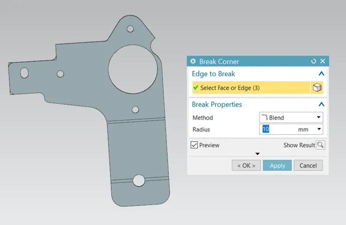
5. Use Break Corner to smoothen sharp edges
- Break Corner: Rounds or chamfers sharp corners of a tab or a flange.
6. Use Normal Cutout again to make the slots and holes in the body
7. Use Break Corner in the inner edges of the square slot
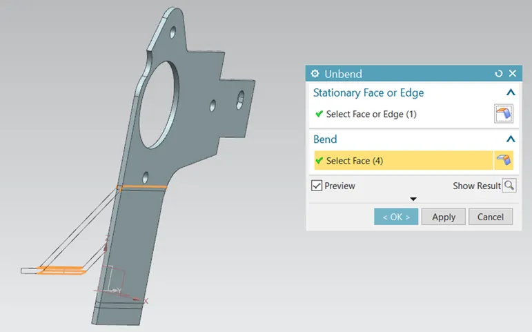
8. Unbend the model
- Unbend: Flattens a bend and the material adjacent to the bend.
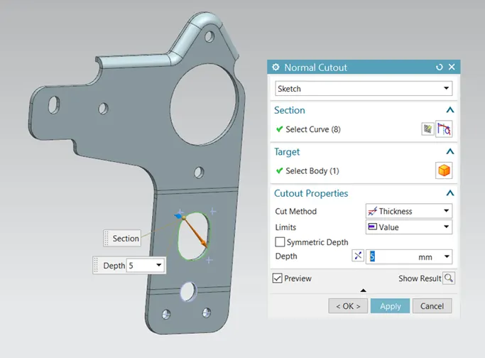
9. Create the Normal Cutouts
10.Create the 2 Holes
- Hole: Adds a hole to one or more solid bodies in a part or assembly with options of counterbored, countersunk and threaded
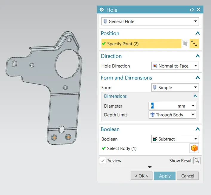
11. Use Break Corner for the edges
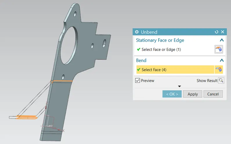
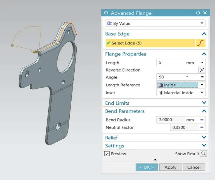
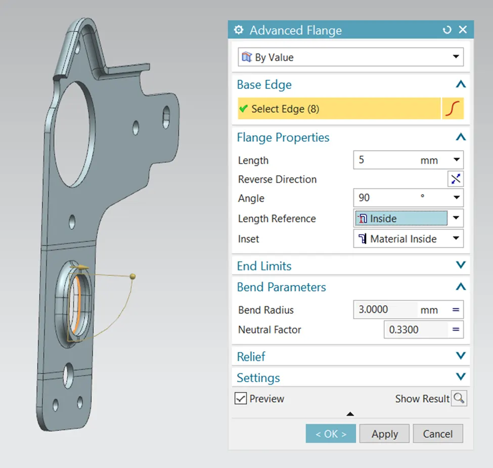
12. Use Advanced Flange
- Advanced Flange: Adds a flange along an edge using a bend angle or reference face. The edge and reference face can be curved.
13. Rebend the model
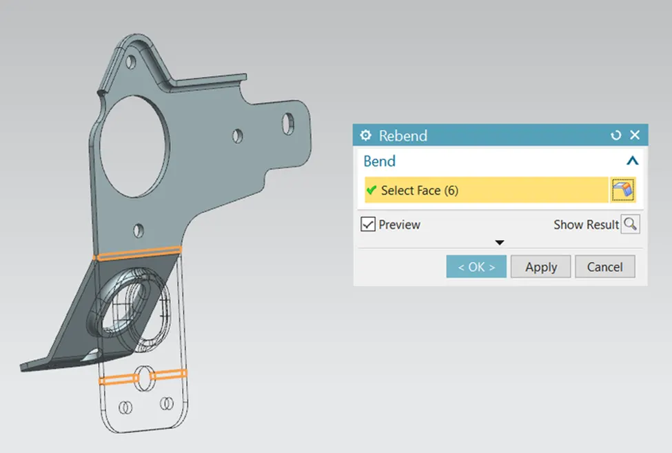
- Rebend: Restores an unbend feature to its previous bent state, along with any features added after the unbend feature.
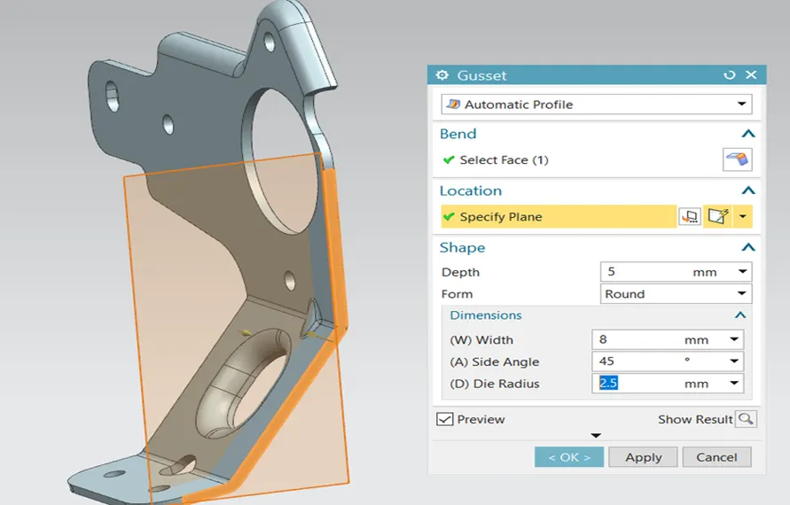
14. Add 4 Gussets
- Gusset: Creates a stiffening gusset on the part. Gussets are used to reinforce bends of all types.
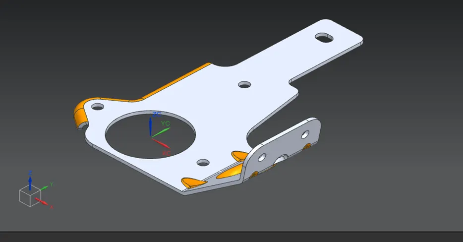
Views
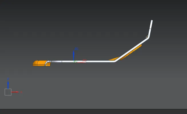
Front View
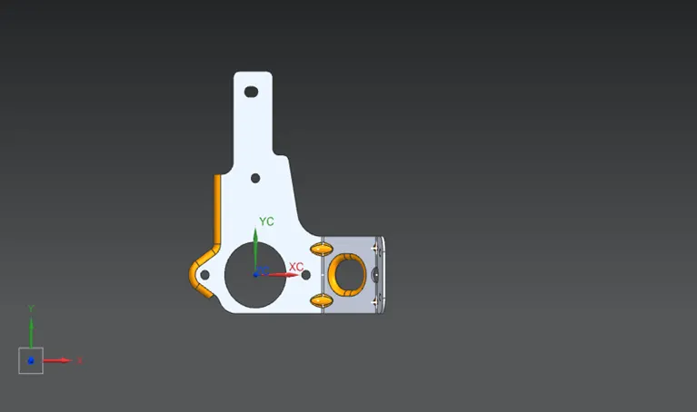
Top View
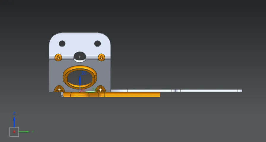
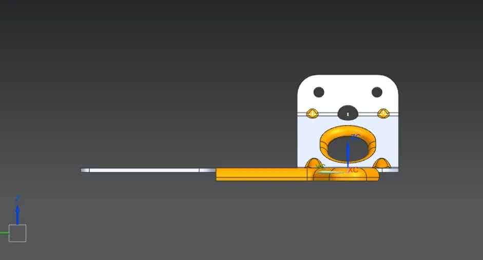
Side Views
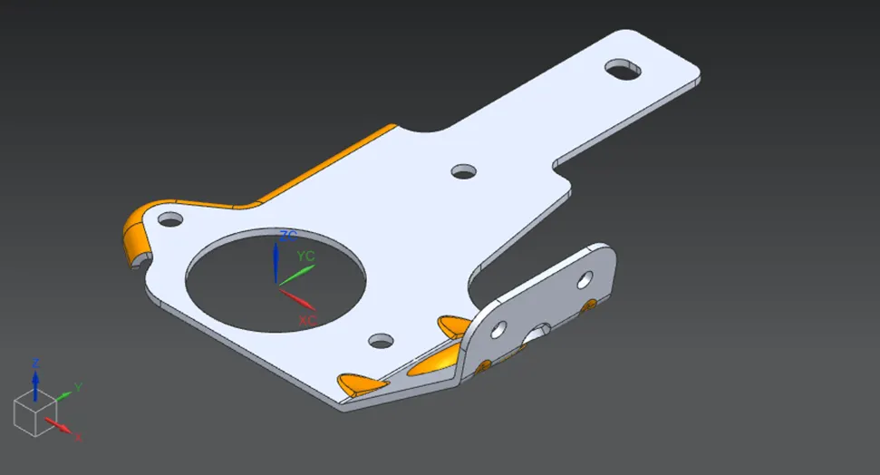
Isometric Views
Conclusion
Thus, the Bracket was designed using the inputs provided and saved in .stp format for future use in creating other models