Design of Metal bracket using Advanced Sheet Metal in _NX_ CAD
Design of Metal Bracket
Objective: Design of Metal Bracket using Siemens NX CAD.
Introduction:
NX, formerly known as "unigraphics", is an advanced high-end CAD/CAM/CAE, which has been owned since 2007 by Siemens PLM Software. In 2000, Unigraphics purchased SDRC I-DEAS and began an effort to integrate aspects of both software packages into a single product which became Unigraphics NX or NX.
It is used, among other tasks, for:
- Design (parametric and direct solid/surface modelling)
- Engineering analysis (static; dynamic; electro-magnetic; thermal, using the finite element method; and fluid, using the finite volume method).
- Manufacturing finished design by using included machining modules.
The Sheet Metal application provides an environment for the design of sheet metal parts used in machinery, Automotive, Aerospace etc. Enclosures, Brackets, and other parts normally manufactures with a brake press.
In this Sheet metal application we can create complex shapes using basic features like flanges, tabs, jogs etc., by designing the solid model in the modelling environment and then converting it in to a sheet metal part.
Sheet Metal Design methodology:

Description:
The designing of this Metal Bracket in NX involves various options or Features explained below.
Tab: - After creating the 2D sketch in sketcher we use Tab option to convert into the 3D metal sheet of desirable thickness.
Extrude: - To create a solid body other sheet metal we use extrude command and select the drawn closed 2D sketch and provide the length or depth of the solid.
Sheet Metal from Solid: - This command is used to covert a solid body surfaces into a sheet metal body of specified thickness.
Bends: - This option is used to create the bends where ever required by sketching the line on the surface according the required direction of the bend either upwards or downwards with required radius of the bend.
Flange: - This option is used to create the flanges at the edges of the base sheet metal by clicking on the upper or lower edge to get the flange towards up or down respectively.
Contour Flange: - This is a Handy feature which helps to create the front view 2D line sketch of the any complex shape and forming into sheet metal by providing its L
Normal Cutout: - After creating the sketch on the base sheet metal this option used to cut out the part drawn normally i.e., perpendicular to the plane without any stretches.
Break Corner: - To create the fillet to the sharp corner edges we use this option by providing the required radius.
Closed Corner: - This command is used to fill the gaps between the created adjacent flanges which are perpendicular to each other.
Hem Flange: - This command is used to modify the model by folding the edge of a sheet metal flange over onto itself for the purpose of the safe handling or to increase edge stiffness.
Advanced Flange: - It adds a flange along an edge using a bend angle or reference face. The edge of the reference face can be curved.
Unbend: This option is used to unbend the modified or deformed sheet metal into straight un-deformed sheet.
Dimple: This command is used to create a raised dimple feature in a sheet metal part. The dimple(s) can be placed on any flat face including flanges and will extend in the direction of the face. The dimple feature will be governed by the settings defined in the Options Form.
Bead: - A bead is a long, drawn-out impression, which is impressed to increase stiffness in metal sheets or plates. Depending on the workpiece size and material thickness, the ratio of length, width and imprint depth must be adjusted to obtain the maximum strengthening effect
Hole: - It is command used in sheet metal application where it asks us to provide the specified points where we require the holes in a sheet metal and it simply crates a holes with the specified diameter.
Re-bend: It helps to re-bend the sheet to its original shape.
Mirror: - Mirror can applied for both the bodies and features where we can create or copy the same features or body with respect to the any other plane of surface.
Unite: - This command helps to unite the two mirror bodies together to form a single object.
Flat Pattern: - After the object is completely finished and to produce the machining drawing we use flat pattern option to create the detailed flat sheet with all the features marked on it along with its description.
Drafting: - Ctrl+ shift+ D helps to move to the draft window where we need to create the new sheet to produce the 2D drawings for printing.
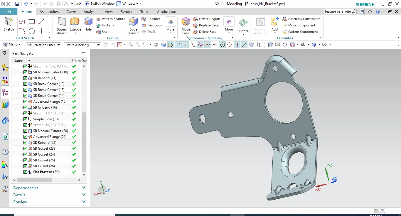
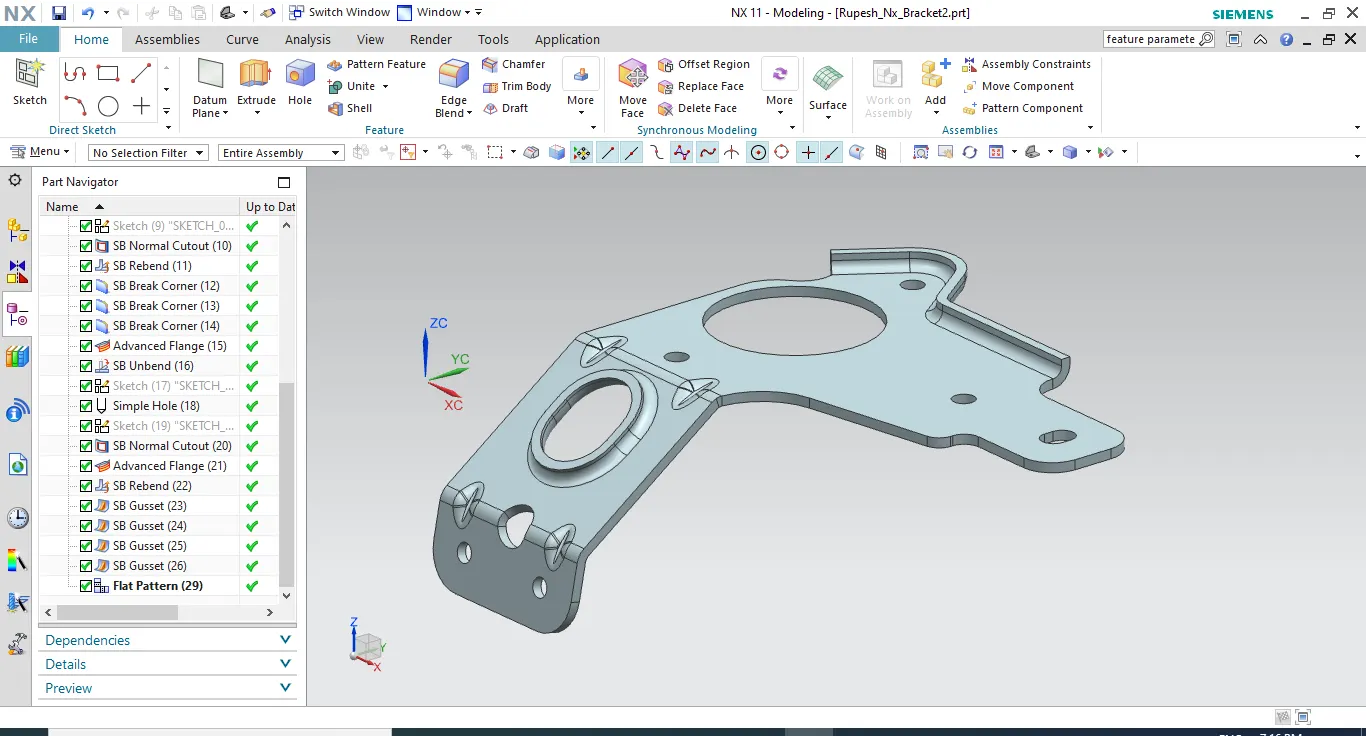
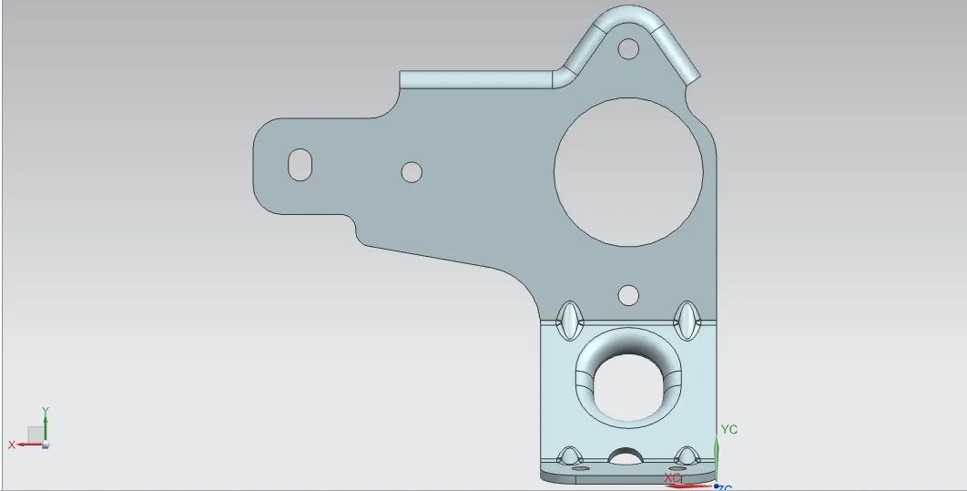
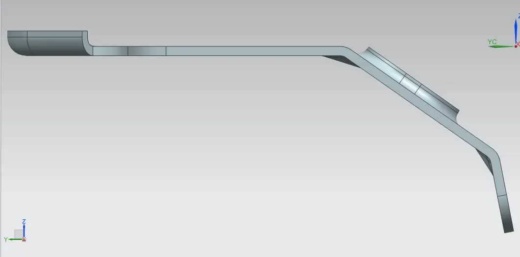
various views of the model are shown below:
Isometric View:
Front View:
Side View:
Drafting:
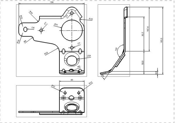
Conclusion: -
Thus simple Metal Bracket is designed using NX_CAD.