Advanced Sheet Metal Design Using NX Cad Challenge_7_ Metal bracket-II
Create ‘Metal Bracket’ from the 2d Drawing in NX Cad
Objective:
The main objective of this project is to design Create ‘Metal Bracket’ from the 2d Drawing in NX Cad in sheet metal application.
Introduction
Sheet metal is metal formed by an industrial process into thin, flat pieces. Sheet metal is one of the fundamental forms used in metalworking, and it can be cut and bent into a variety of shapes. Countless everyday objects are fabricated from sheet metal. Thicknesses can vary significantly; extremely thin sheets are considered foil or leaf, and pieces thicker than 6 mm (0.25 in) are considered plate steel or "structural steel".
Sheet metal is available in flat pieces or coiled strips. The coils are formed by running a continuous sheet of metal through a roll slitter.
Forming Process
- Bending 11. Photochemical machining
- Curling 12. Perforating
- Decambering 13. Press brake forming
- Deep drawing 14. Punching
- Expanding 15. Roll forming
- Hemming and seaming 16. Rolling
- Hydroforming 17. Spinning
- Incremental sheet forming 18. Stamping
- Ironing 19. Water jet cutting
- Laser cutting 20. Wheeling
Applications
- Automotive Industries
- Construction Industries
- Oil & Gas Industries
- Aerospace Industries
Design Methodology:
|
Sketch on the selected plane(Y, Z) |
|
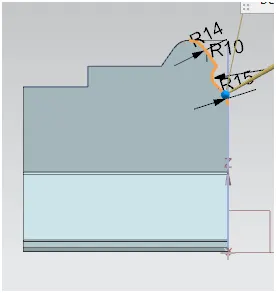
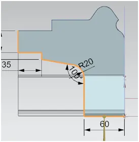
Adding the features contour flange, normal cut out, Break the corner points |
|
Sketch on the selected plane(Y, Z) |
|
Adding the features unbend, re-bend and breaking corners |
|
Sketch on the selected plane(Y, Z) |
|
Adding feature like advanced flange, unbend |
|
Sketch on the selected plane(Y, Z) |
|
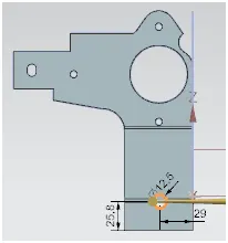
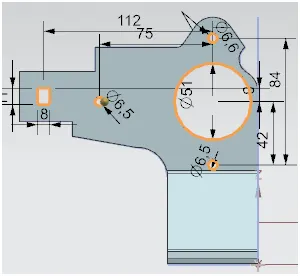
Adding the features simple hole, normal cut out |
|
Sketch on the selected plane(Y, Z) |
|
Adding feature like re-bend, advanced flange and gusset...etc |
Description:
The sheet metal Create ‘Metal Bracket’ from the 2d Drawing has been done with the above flow chart process. In the NX Cad using default thickness, bend radius, relief depth & width values are set to 3 mm
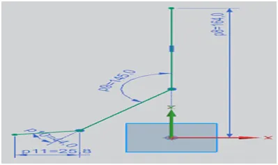
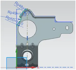
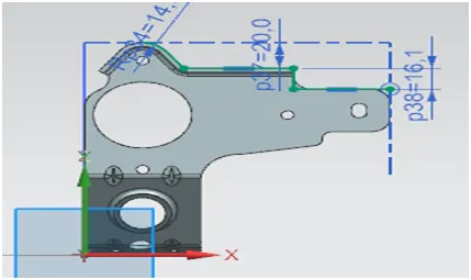
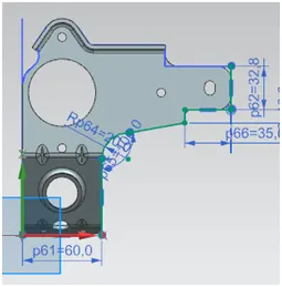
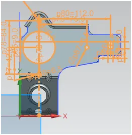
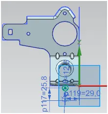
2D Sketch:
2D Sketching in Drawings. You can create drawing geometry using 2D sketched geometry only, without reference to existing models or assemblies. ... When you drag a sketch point in a drawing, it snaps or infers to other sketches, drawing views blocks, and items in the sheet format.
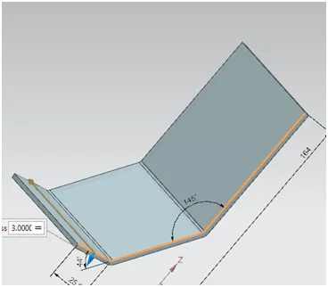
Contour flange:
Creates a base feature by extruding a sketch along a vector, or adds material by sweeping a sketch along an edge or chain of edges.
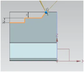
Normal Cut out:
The command is used to cut the material on the exists sketch on the plane.
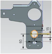
Break corners:
This command is used to create the round/fillet the sharp corners.
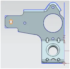
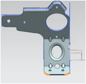
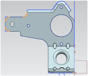
Unbend:
This command is used to unbend the sheet metal. The punching & drilling operation can be performed by only flat planes only.
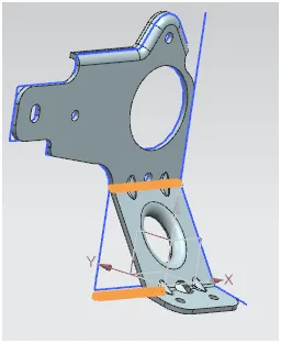
Re-bend:
After finish all these operations then we should to re-bend the un-bended parts.
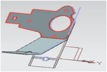
Holes:
In the Hole feature we can select the points and type requirement we need it.
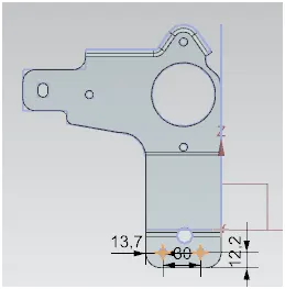
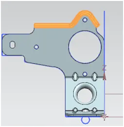
Advanced Flange:
Adds a flange along an edge using a bend angle or reference face. The edge and reference face can be curved
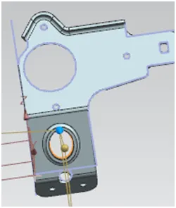
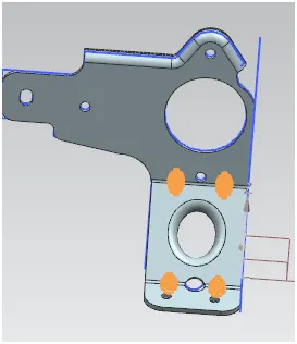
Gusset:
Creates a stiffening gusset on the part.
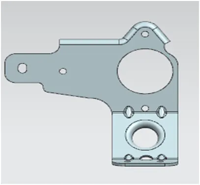
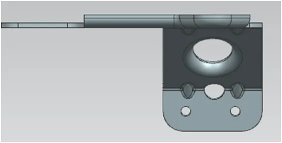
Front view:
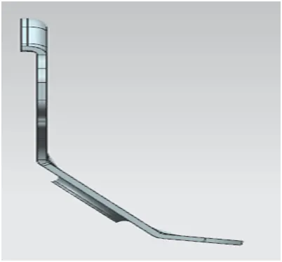
Side view:
Top view:
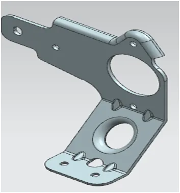
Isometric view:
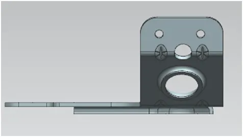
Bottom view:
Conclusion:
The sheet metal Create ‘Metal Bracket’ from the 2d is successfully completed in NX Cad.