Advanced Sheet Metal Design Using NX Cad Challenge_7_ Metal bracket-II
DESIGNING A SHEET METAL BRACKET-II using NX-CAD
Objective:
• To learn and implement the principles of Advanced Sheet Metal design to design a bracket using NX CAD as a tool.
• To understand Sheet Metal applications and its importance as per industry standards.
Introduction
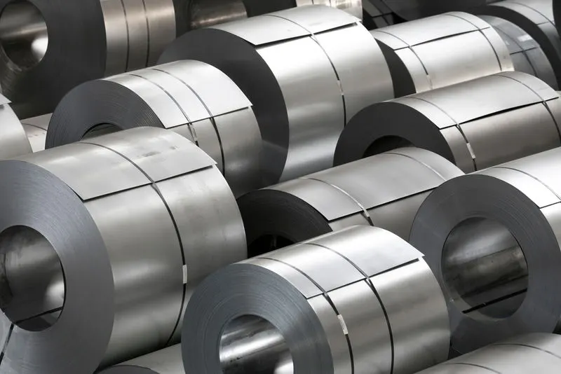
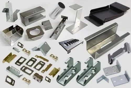
Sheet metal is metal formed by an industrial process into thin, flat pieces. Sheet metal is one of the fundamental forms used in metalworking, and it can be cut and bent into a variety of shapes. Countless everyday objects are fabricated from sheet metal. Thicknesses can vary significantly; extremely thin sheets are considered foil or leaf, and pieces thicker than 6 mm (0.25 in) are considered plate steel or "structural steel".
NX sheet metal design software incorporates material and process information in sheet metal-specific modeling features: bends, flanges, tabs, cutouts, beads, dimples, louvers, corner and edge treatments, patterns and other formable features. We can also quickly convert solid models to sheet metal components and create sheet metal parts that enclose other components.
With NX sheet metal CAD tools, we can apply standard values, such as material thicknesses and bend radii, based on industry or company best practices. With folding and unfolding capabilities, we can work with models at any stage of the fabrication cess. NX sheet metal software creates accurate flat patterns for documentation and manufacturing.
Metal Bracket:
Metal Bracket is a device that projects from or overhangs a wall to carry weight. It may also serve as a ledge to support a statue, the spring of an arch, a beam, or a shelf. The metal brackets are manufactured by conducting stamping or die casting operations.
Applications of Metal Brackets:
- Bracket for split Air conditioners
- LED television mount bracket
- Cable crimp sleeve brackets in Automobiles
- Hinge Brackets for doors
METHODOLOGY
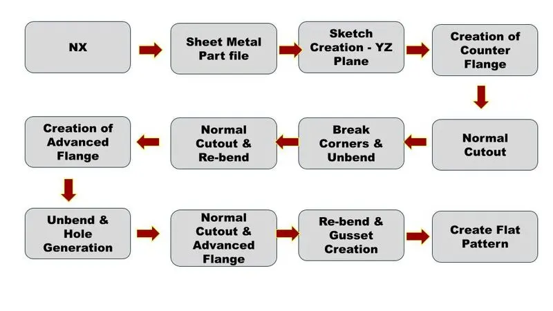
DESCRIPTION:
Sheet Metal- Starts the Sheet Metal application, which provides tools to design straight-brake and more complex sheet metal parts:
Feature Tools: Counter Flange, Break Corners, Unbend, Hole, Normal cutout, Gusset, Re-bend, Advanced Flange, Flat Pattern.
Counter Flange- Creates a base feature by extruding a sketch along a vector or adds material by sweeping a sketch along an edge or chain of edges.
Break Corner - Rounds or chamfers a sharp corner of a tab or flange.
Unbend-Flattens a bend and the material adjacent to the bend.
Hole - Adds a hole to one or more solid bodies in a part or assembly with options for counterbored, countersunk, and threaded.
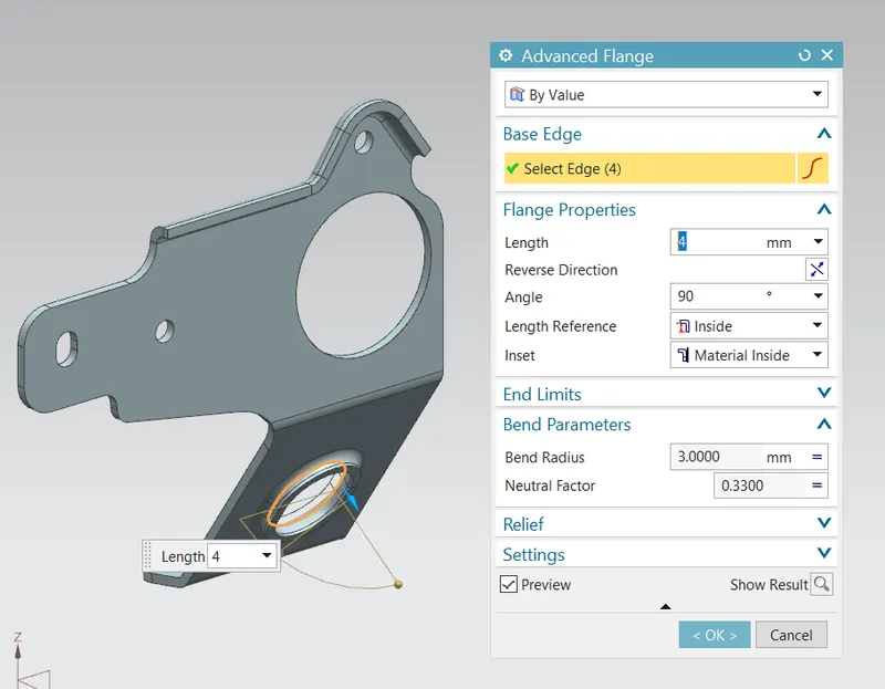
Advanced Flange - Adds a flange along an edge using a bend angle or a reference face. The edge and reference face can be curved. Re-bend- Restores an unbend feature to its previous bent state, along with any features added after the unbend feature, Gusset - Creates a stiffening gusset on the part.
Flat pattern-Creates a flat pattern from the formed sheet metal part
Drafting - Starts the Drafting application, which provides tools to create and maintain drawings of the design model
Feature Tools: New Sheet, Base View.
New Sheet-Creates a new drawing sheet.
Base View - Creates a model-based view on the drawing sheet.
PROCEDURE:
- Open a new Sheet Metal Part file and save it
2. Sketch Creation:
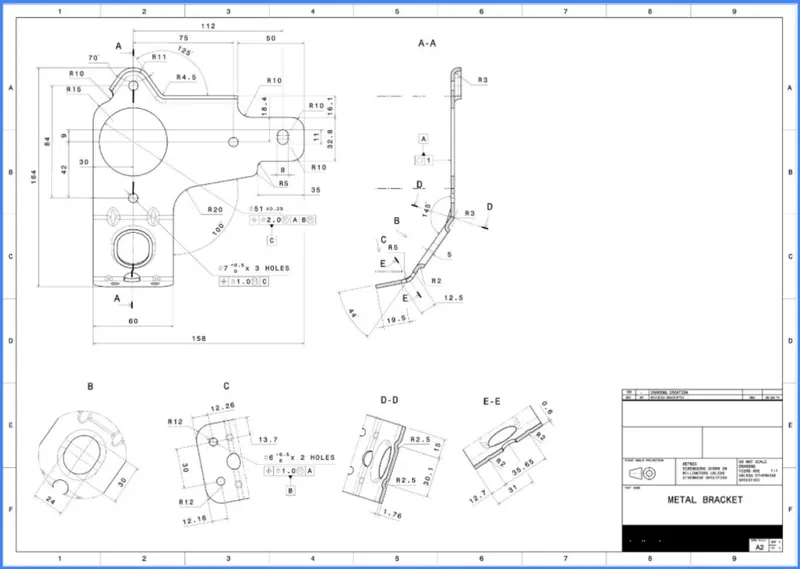
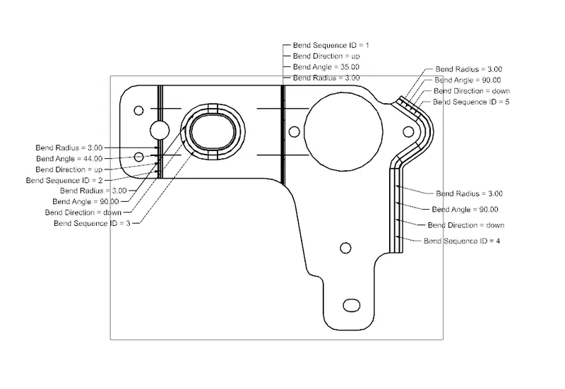
- XYZ Plane - Create a sketch as per drawing using lines, circles, rectangles & arcs. Exit the sketch.
3. Counter Flange Creation:
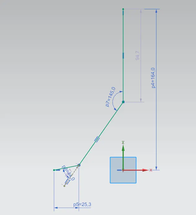
- XZ Plane - Create a sketch as per 2D drawing using lines, arcs, and fillets. Apply dimensions and relations to it and exit the sketch.
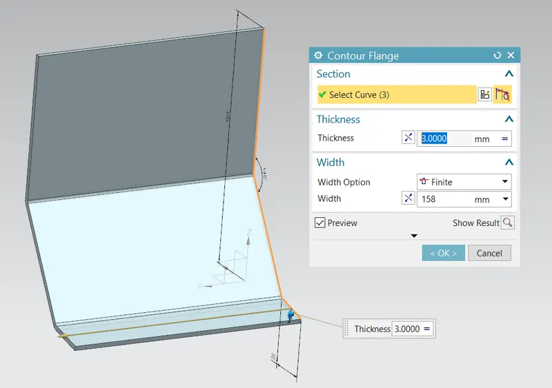
- Use the Counter Flange feature and select the sketch and extrude it.
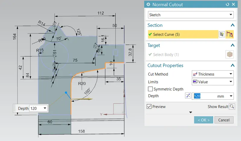
4. Normal Cutout:
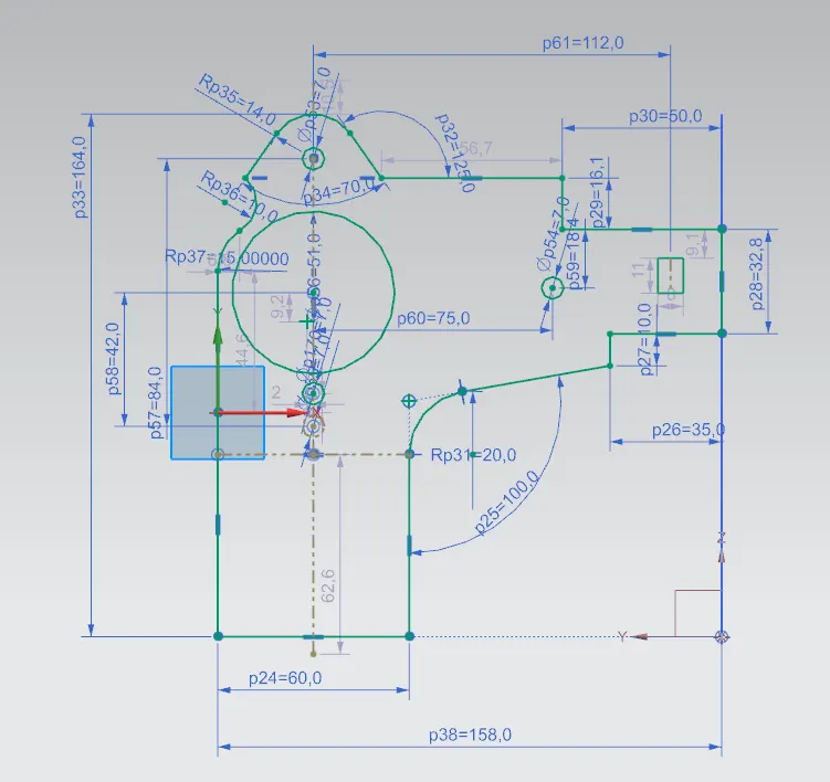
- XY Plane - Create a sketch by drawing as per drawn sketch in step 2 using lines & arcs. (the portion that has to be removed). Exit the sketch.
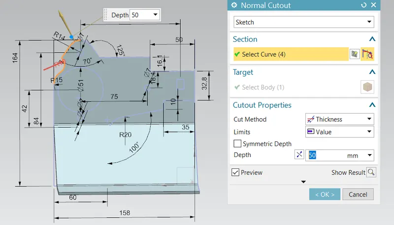
- Use the Normal cutout feature to cut the unwanted material
- Similarly, repeat the steps on the other sides also.
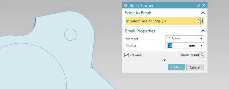
5. Breaking Corners:
- Apply fillets to the required edges by using the Break comers feature.
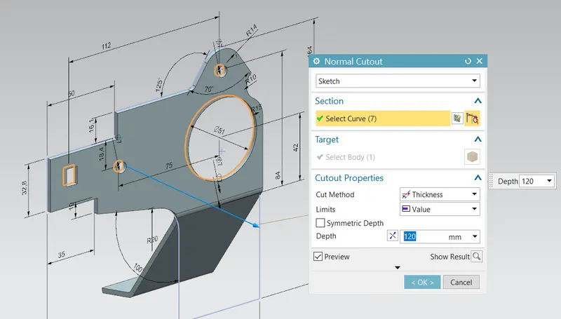
6. Normal Cutout:
- XY Plane - Create one more sketch by drawing as per the drawn sketch in step 2 using circles in the middle portion (the portion that has to be removed). Exit the sketch.
- Use the Normal cutout feature to cut the unwanted material.
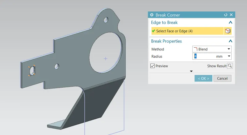
7. Breaking Corners:
- Apply fillets to the rectangular edges by using the Break corners feature.
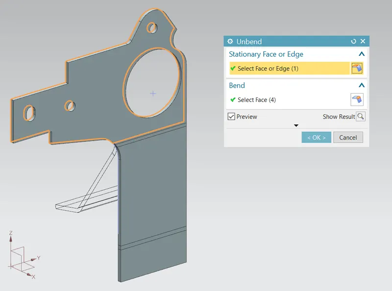
8. Unbend Sheet Metal
- Unbend the sheet metal by selecting stationary face as larger face & bend faces to bend.
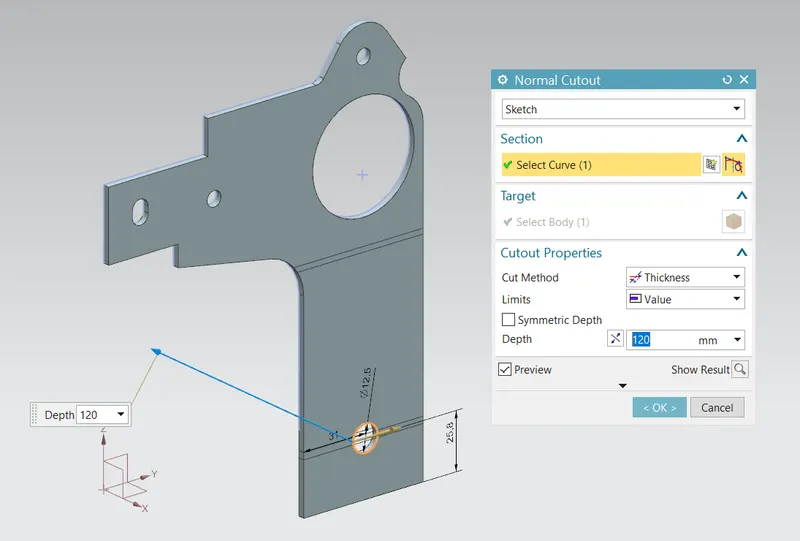
9. Normal Cutout:
- YZ Plane - Create a sketch by drawing a circle at the bottom portion (to make hole), Exit the sketch.
- Use the Normal cutout feature to cut the unwanted material.
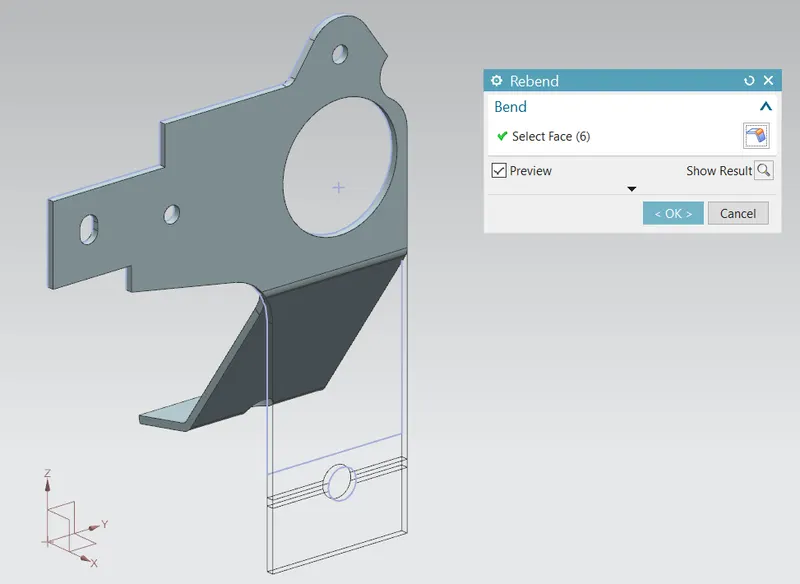
10. Re-bend Sheet Metal:
- Re-bend the sheet metal by selecting Bend face which is previously used to unbend:
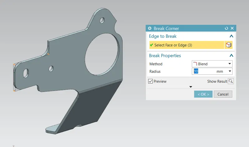
11. Breaking Corners:
- Apply fillets to the bottom edges by using the Break corners feature.
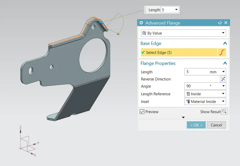
12. Advanced Flange Creation:
- Select the top edges of the Bracket and use the Advance flange feature to curve it.
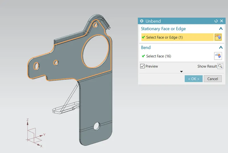
13. Unbend Sheet Metal:
- Unbend the sheet metal by selecting stationary face as larger face & bend faces to bend.
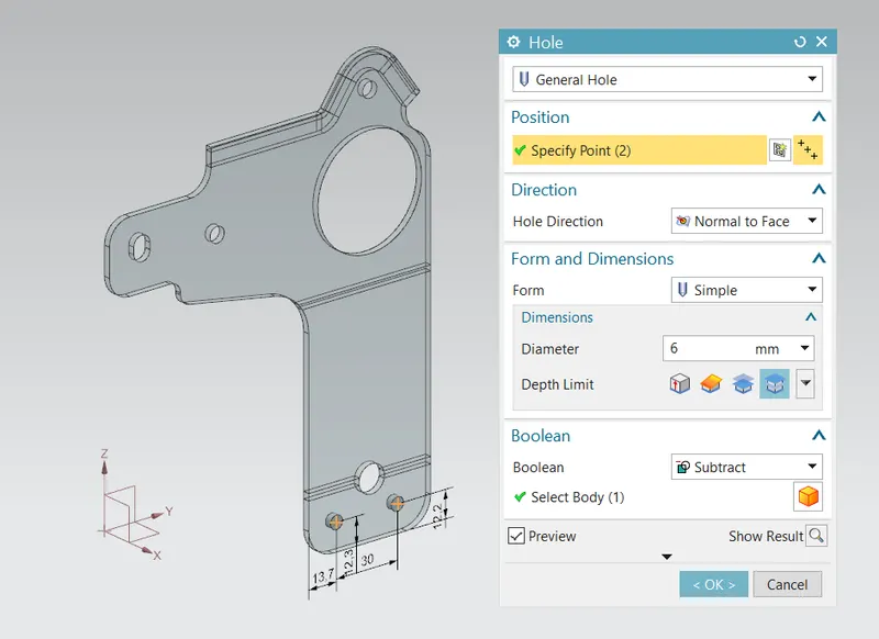
14. Adding Holes:
- XY Plane - Create a sketch by drawing a few sketch points as per drawing.
- Use the Hole feature to create holes.
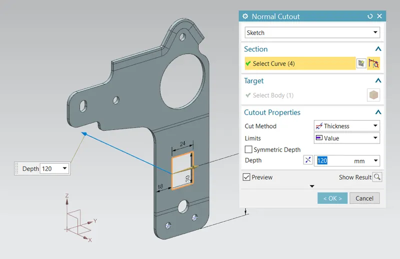
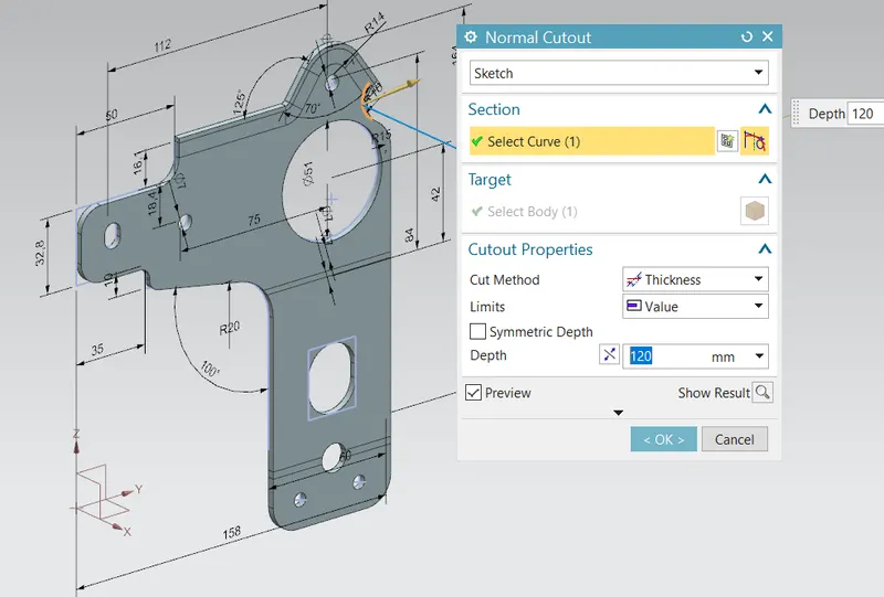
15. Normal Cutout:
- YZ Plane - Create a sketch by drawing an Ellipse shape using lines & arcs at the bottom portion (to make a hole). Exit the sketch.
- Use the Normal cutout feature to cut the unwanted material.
- Do one more Normal cutout at the left top edge as per the drawing.
16. Advanced Flange Creation:
- Select the edges of the created normal cutout in step 15 and use the Advance flange feature to curve it.
17. Re-bend Sheet Metal:
- Re-bend the sheet metal by selecting Bend face which is previously used to unbend.
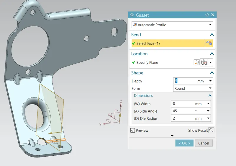
18. Creation of Gussets:
- Select the bent face and Proper plane in the Gusset feature to create the gusset.
- Create one more gusset at the same place at a distance. iii. Repeat the same procedure at the lower bend face to create Gussets.
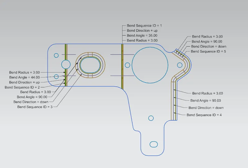
19. Drafting:
- Use Flat Pattern and select the flat face to create a flat pattern.
- Create a new drafting file of A4/A3/A2 Size and add Base view by giving proper scale(Rotate the model if required).
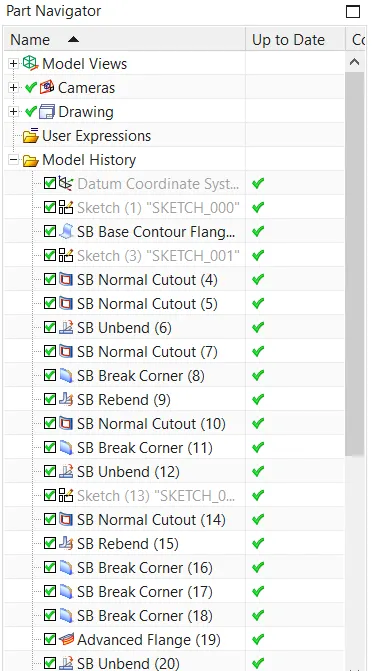
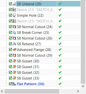
Feature Tree
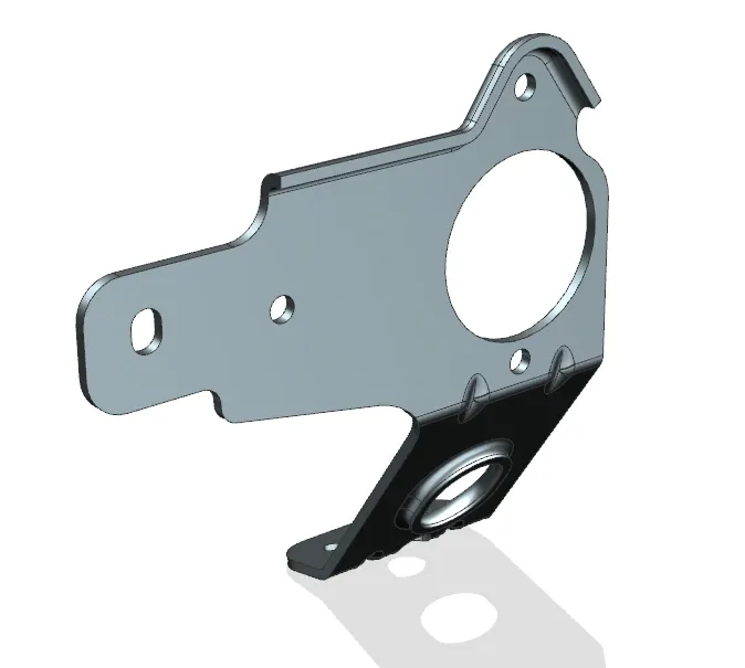
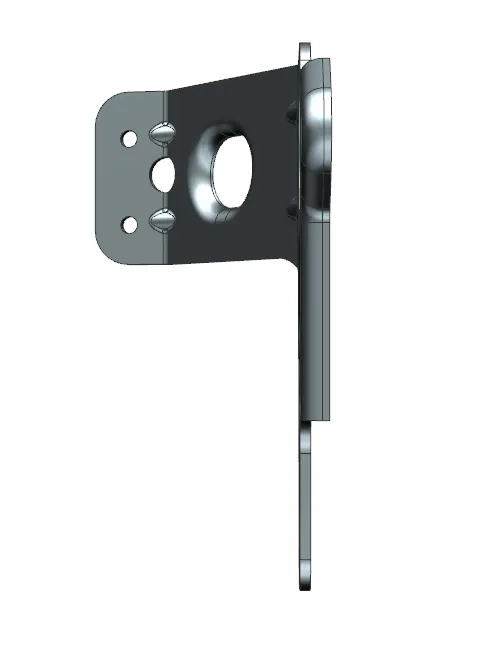
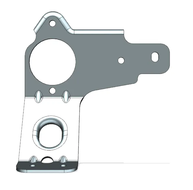
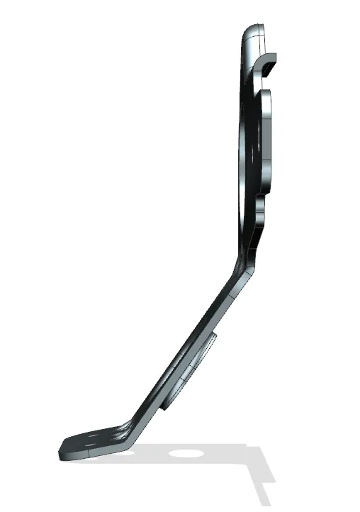
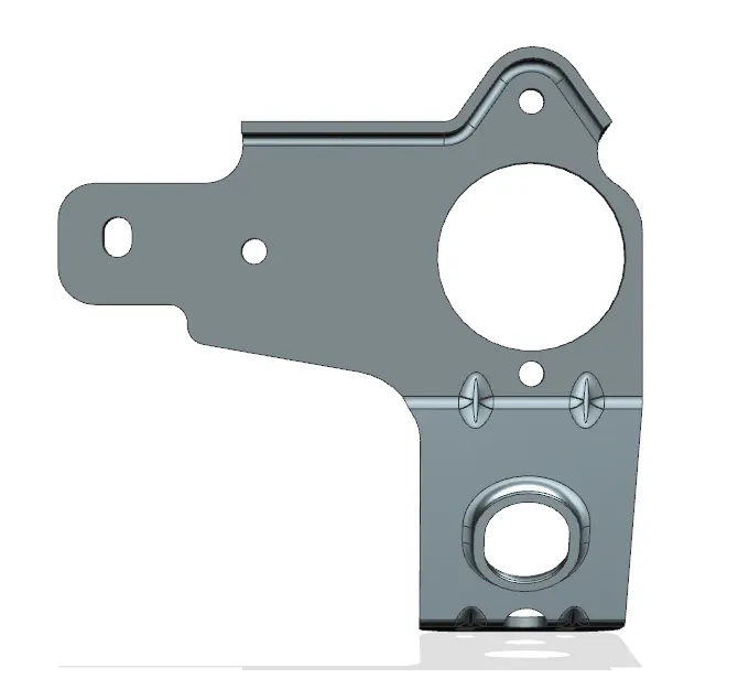
View of the Bracket
CONCLUSION:
In the end, Bracket Designed in NX cad using Sheet metal as an application. Additional features like Gussets, holes were added as per the Drawing.