Advanced Sheet Metal Design Using NX Cad Challenge_6_Bracket
Objective: To design a Bracket using Siemens NX Sheet metal application.
DESIGN METHODOLOGY:
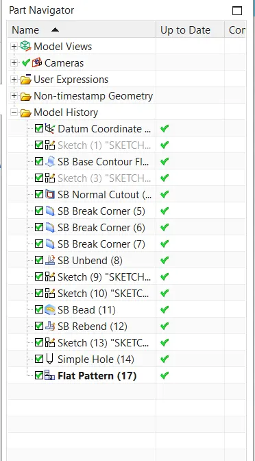
- Open new sheet metal part in NX cad
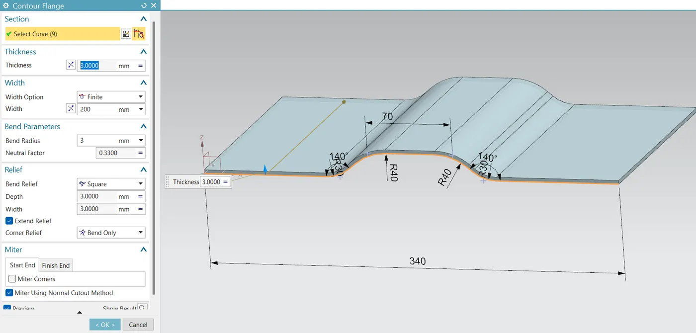
- Create contour flange using sketch with given parameters
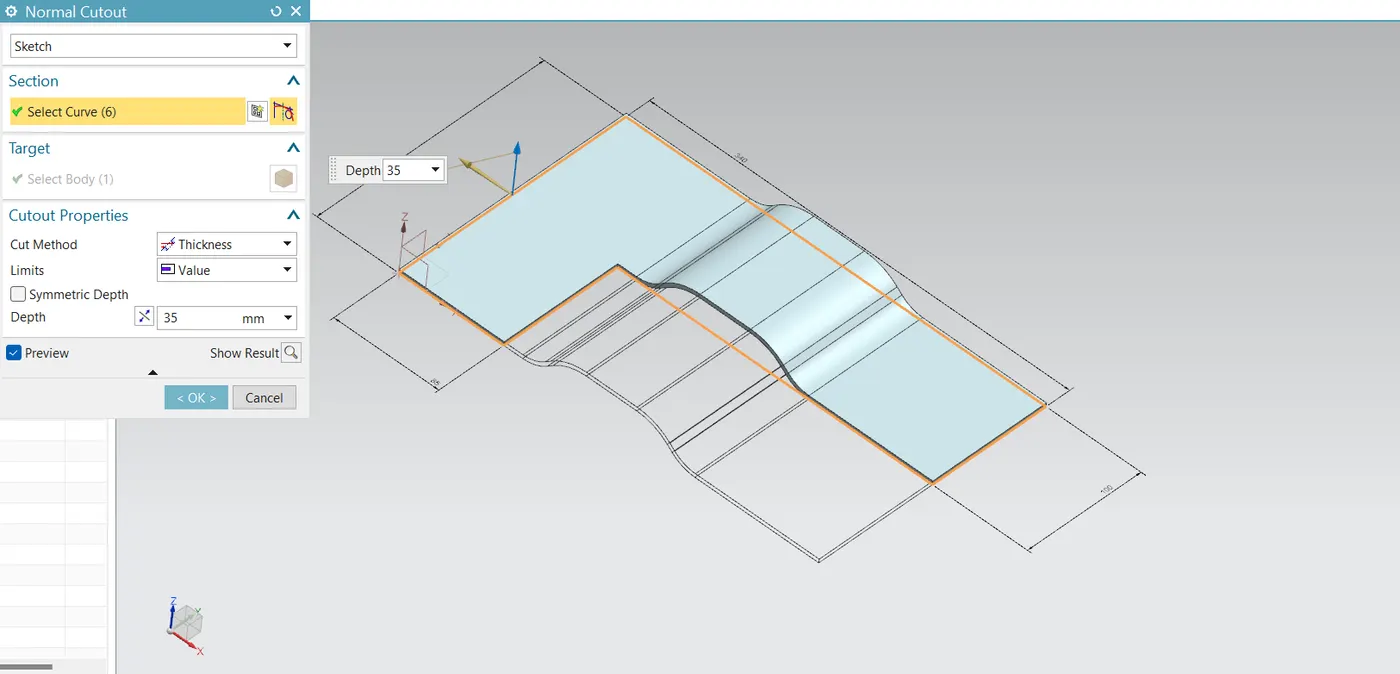
- Cut the body using normal using given dimensions
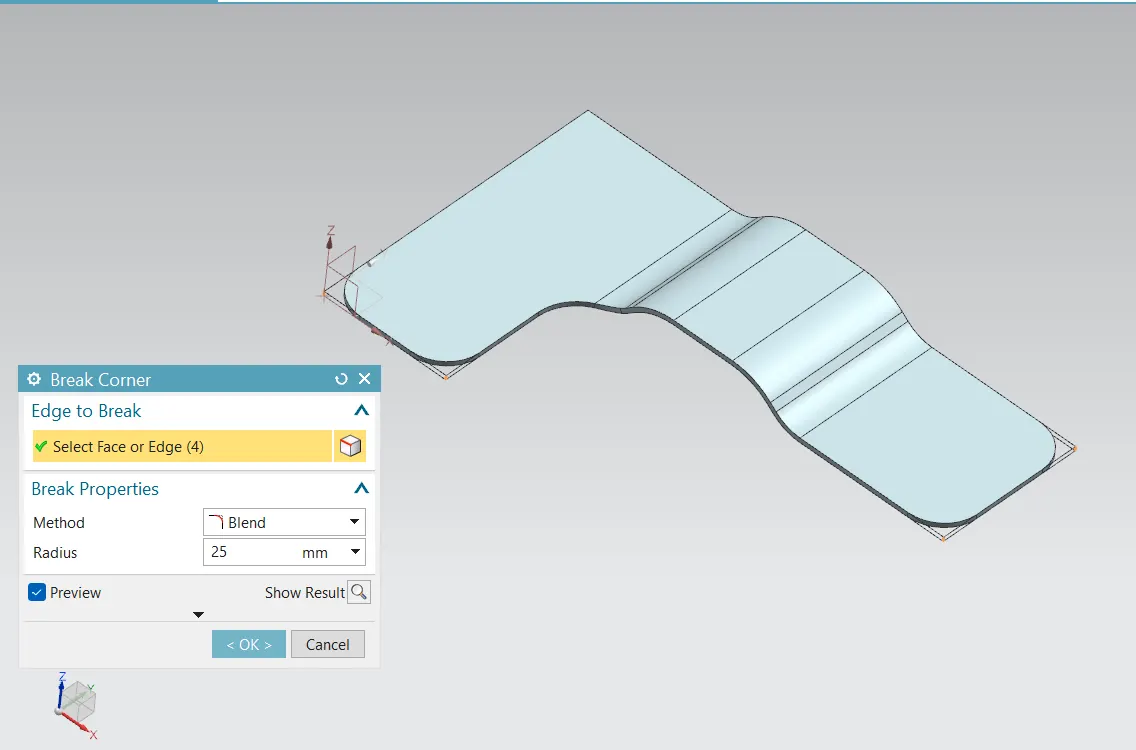
- Give some break corners with required dimensions
- Unbend the model and create bead with using line sketch
- Create some holes as per requirements
- Rebend the model
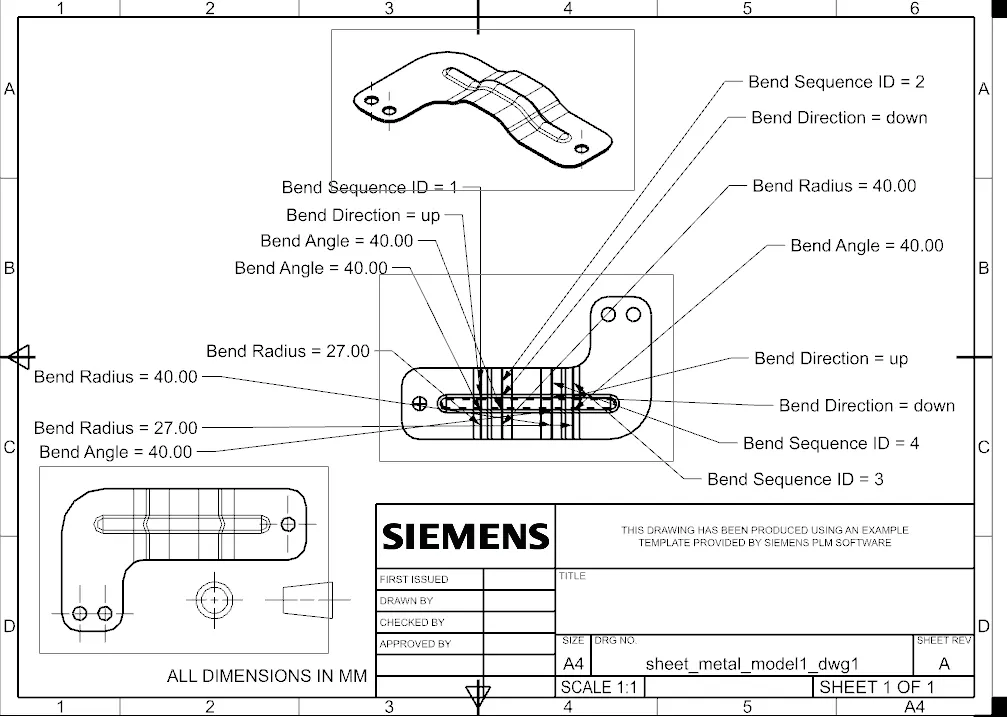
- If required create the drawing sheet using draft tool for understanding to customer
- Hence the model is ready
Description :
Create the base sketch from reference to the given bracket sketch. Create the sketch profile as shown in the below picture
By using contour flange, create the base to a length of 200 mm
Create a sketch on top plane.Create the normal cut out from the drawn profile
Smoothen the sharp corners using break corner option with a radius values of 25 mm on the outer edges, 30 mm for the inner edge and 60 mm in the corner.
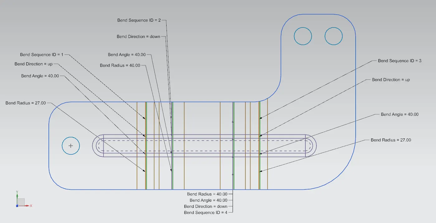
Create sketch for bead
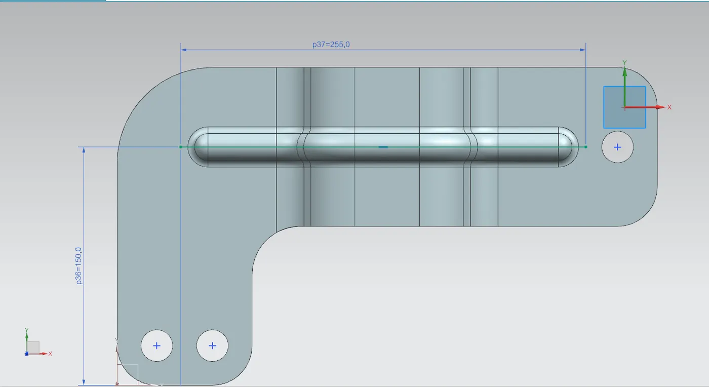
Unbend the bracket
Create bead form the profile created
Rebend the bracket
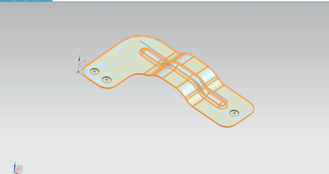
Create a points on top view to locate the holes.Create the holes using hole command
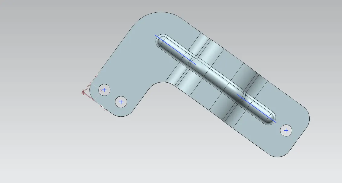
View 1
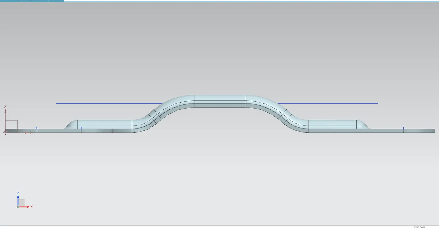
Isometric view
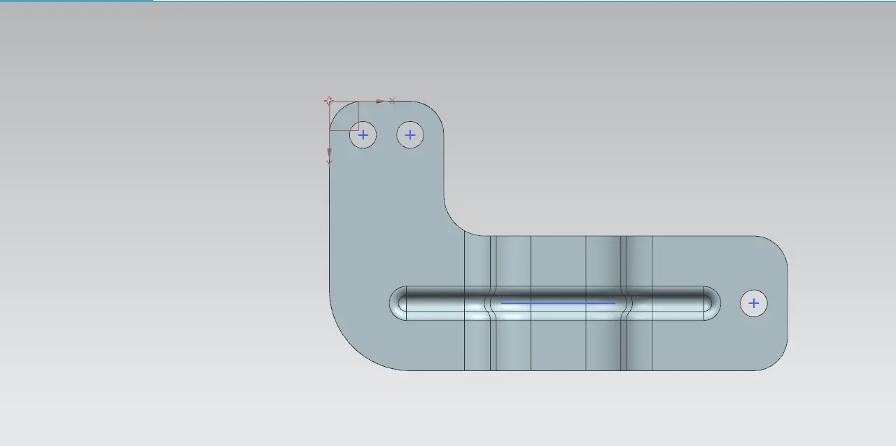
Conclusion:
The metal bracket is created using advanced sheet metal tools in NX CAD.