Advanced Sheet Metal Design Using NX Cad Challenge_6_Bracket
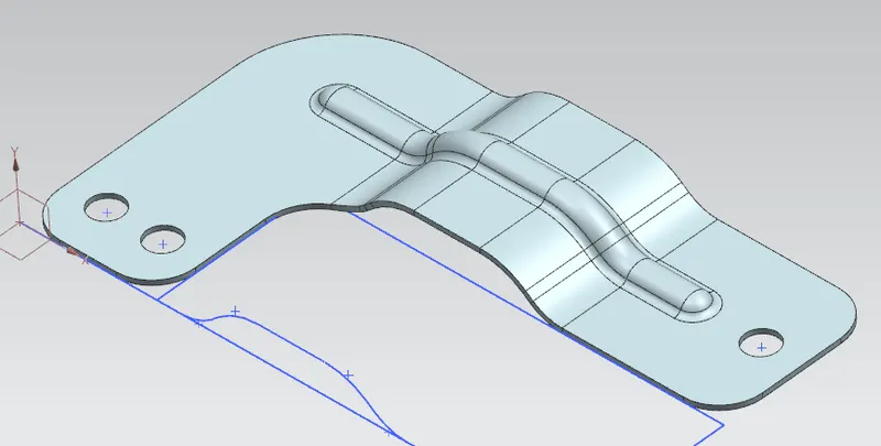
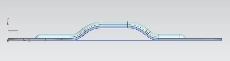
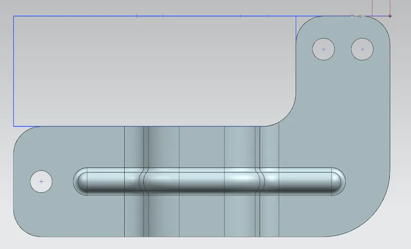
SHEET METAL DESIGN OF BRACKET USING NX CAD
OBJECTIVE
To design a sheet metal Bracket by using siemens NX cad software.
INTRODUCTION
Sheet metal Design is the process of making thin sheet metal into different forms done by the of NX cad software. This helps to know how to use the basic type of sketch tool, Bends, Corners, Punches, Forms, Features in NX Cad.
METHODOLOGY
- Sketch
- Counter flange
- Normal Cutout
- Break corner
- Bead
- Unbend
- Rebend
- Hole
- Drafting
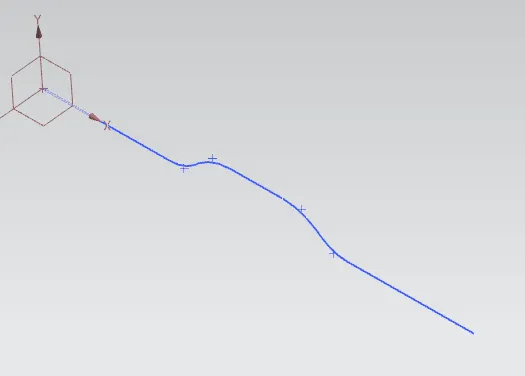
Sketch
This command used for creating the sketch required for tabs, cut out, dimple, bead etc.
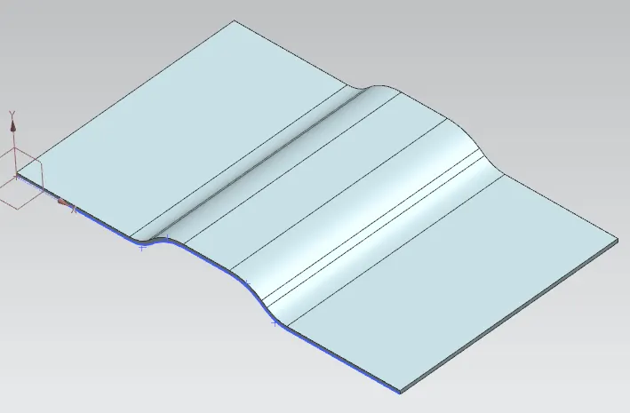
Counter flange
This command is used for extruding a sketch along a specified vector to form a base feature.
Normal Cutout
Normal Cutout command extract volumes from sheet metal by using sheet metal production principles. Cutting faces will be perpendicular to the sheet metal. 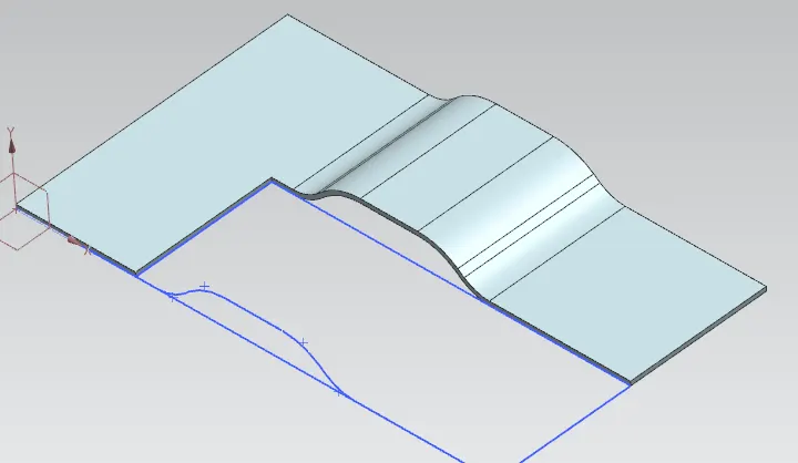
Break corner
This command is used to fillet or chamfer the sharp corners of a tab or flange. 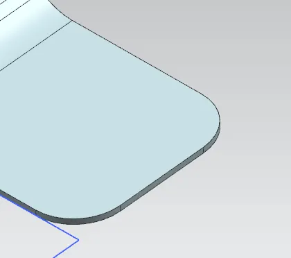
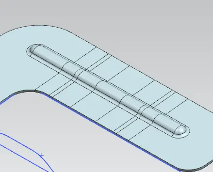
Bead
It is used for giving strength to the sheet metal.
Unbend
This command is used to unbend the adjacent bends and flatten them back to tab. 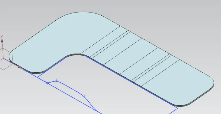
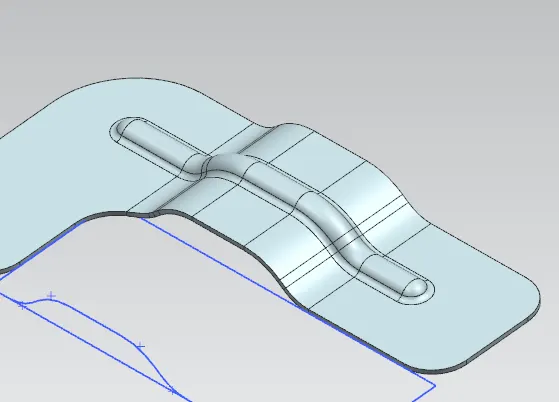
Rebend
This command is used for re bend the sheet metal.
Hole
It adds holes on sheet metal parts according to the specified sketch points. 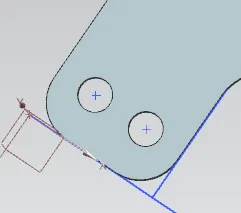
Drafting
We can convert the flat pattern of the model to a 2D draft on a drafting sheet.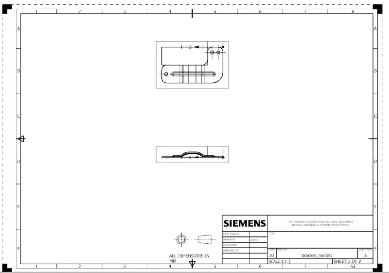
Conclusion
This project underlines the tools used for designing a sheet metal bracket in NX cad software.