Advanced Sheet Metal Design Using NX Cad Challenge_6_Bracket
MODELLING OF BRACKET
OBJECTIVE: This project aims to design the bracket using sheet metal modelling in the NX cad sheet metal workbench.
INTRODUCTION: The present project to develop a bracket using NX Cad requires convenient designing along with subsequent operations to perform to get the desired design. The following operations are performed on the casing are as follows:
- Contour flange
- Normal Cutout
- Break Corner
- Unbend
- Bead
- Rebend
- Hole
All the sketch profiles are made fully constrained with respect while performing the subsequent operation with the following sketches.
DESIGN METHODOLOGY: The flow chart resembles the sequence in which the process follows:
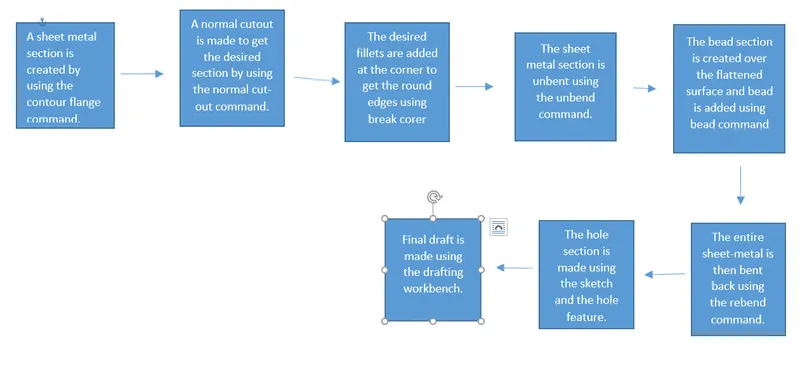
DESCRIPTION: The bracket is designed with subsequent operations that use various features described as follows along with the flow with which we design the bracket. After sketching the XY plane it is extruded using the contour flange command.
Contour flange- When an open profile or a path is extruded along a certain direction with a certain thickness, this feature is used. A sketch section after creation is protruded to do the subsequent cut-out.
A closed section that is needed is cut out from this prior sheet by using the normal cut-out method.
Normal Cut-out- This feature takes out the sheet metal section from the extruded part and is used to extract a surface from the previously created tab.
The sharp edges are given round smooth corners by using the break corner command.
Break Corner- It is similar to a fillet feature where a blend is used to provide a smoother section with a suitable radius.
The following part obtained until now is unbent using the unbend feature in sequential order.
Unbend- To unbent back the bent sheet a stationary face along with the stationary edge is used and the adjacent face is then unbent.
After unbending the upper face is used as a reference to make the sketch for bead creation.
Beads- The beads are also similar to the punching operation which embossed the sketch on the sheet metal part.
After the desired result is obtained the sheet is rebend using the rebend command.
Rebend- Similar to selecting the reference edge and the stationary face this command is used to get back the result.
To get the reference points for hole creation points are made and then holes are made over these points.
Hole- A general hole is added on all the four reference points made previously by using the suitable hole.
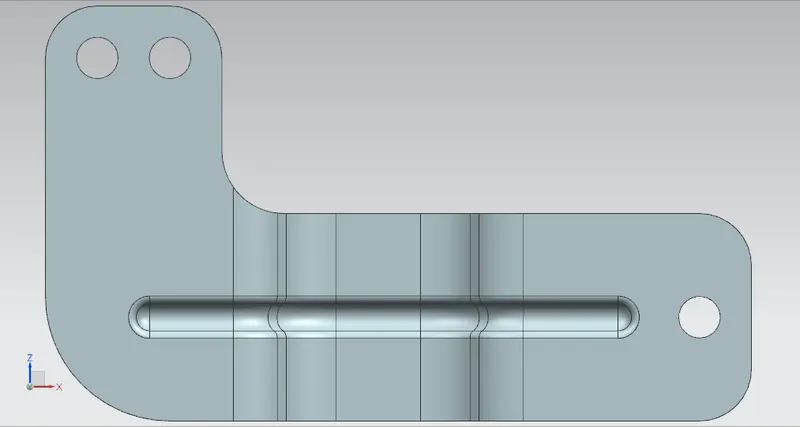
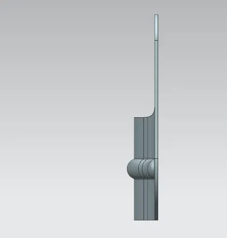
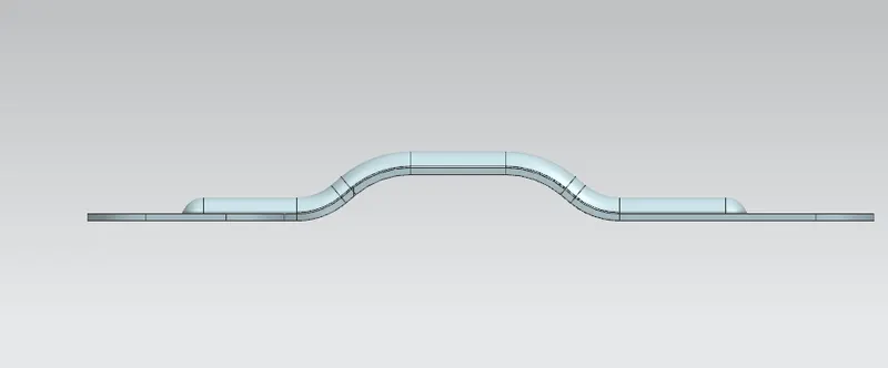
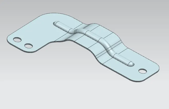
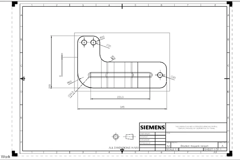
CONCLUSION: Hence the design of the bracket along with the draft is done successfully.