Advanced Sheet Metal Design Using NX Cad Challenge_6_Bracket
BRACKET SHEET METAL
TITLE OF THE PROJECT : Bracket creation using sheet metal
OBJECTIVE :
- Title of the Project
- Objective
- Introduction
- Design methodology / approach (To be explained with the help of Flowcharts only)
- Description (Need to explain tools/ Features used while designing)
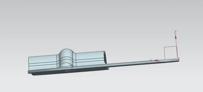
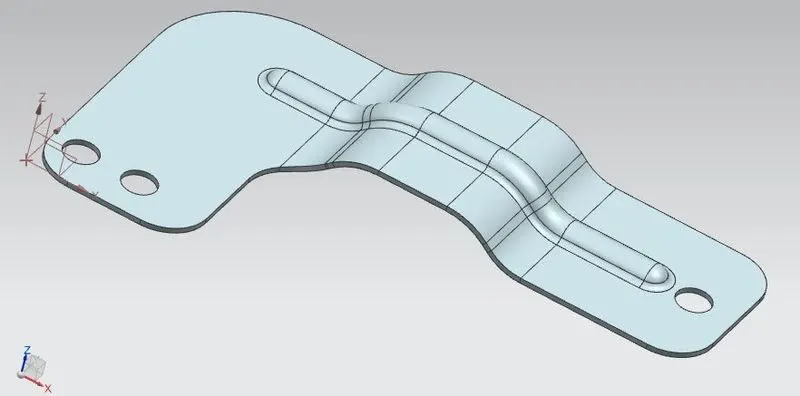
- Upload a min of four screenshots of Model in the report. (Front View, Side View, Isometric View and the Top View)
- Attach Detailed Drawing Sheet Image (If Required)
- Conclusion
DESIGN METHODOLGY
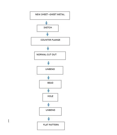
DESCRIPTION
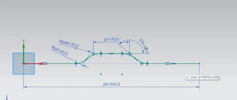
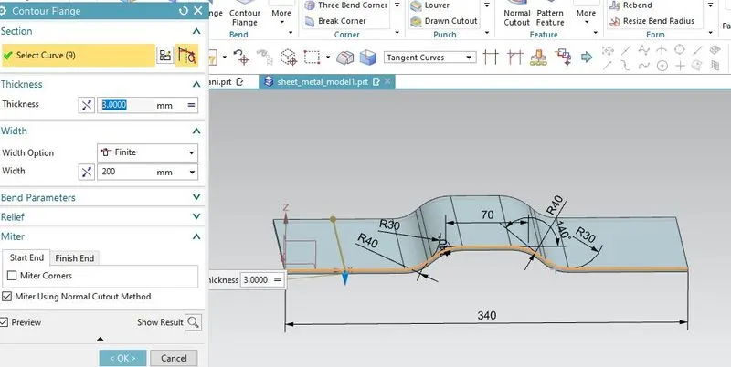
Sketch on the ZX plane .select the counter flange and select the curve ,thickness of 3mm and 200mm length.
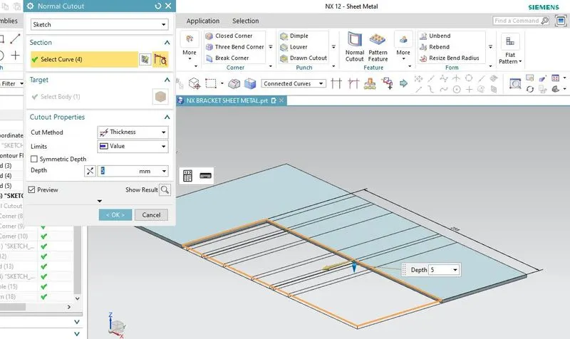
for the normal cut out draw the sketch and select he curve
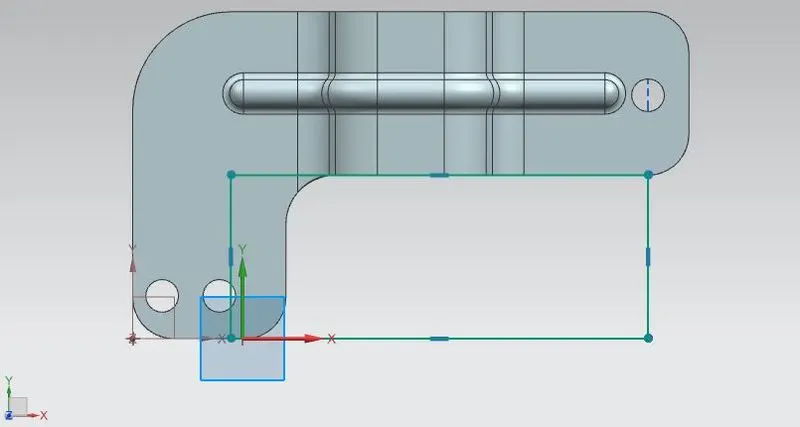
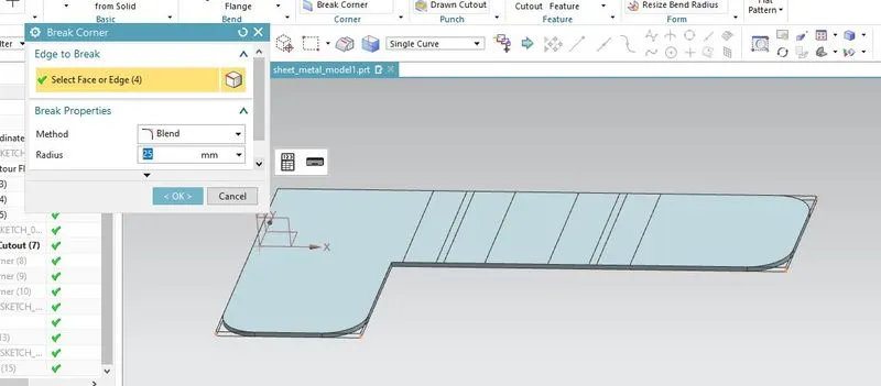
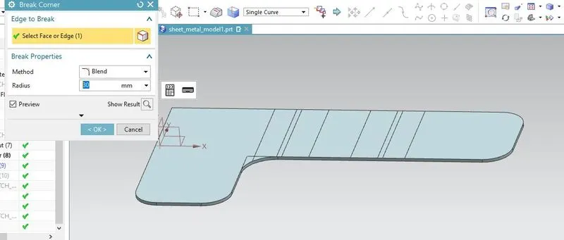
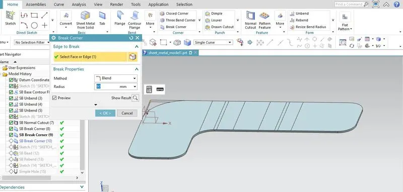
break corners are given for 25.30 and 60 mm radius.
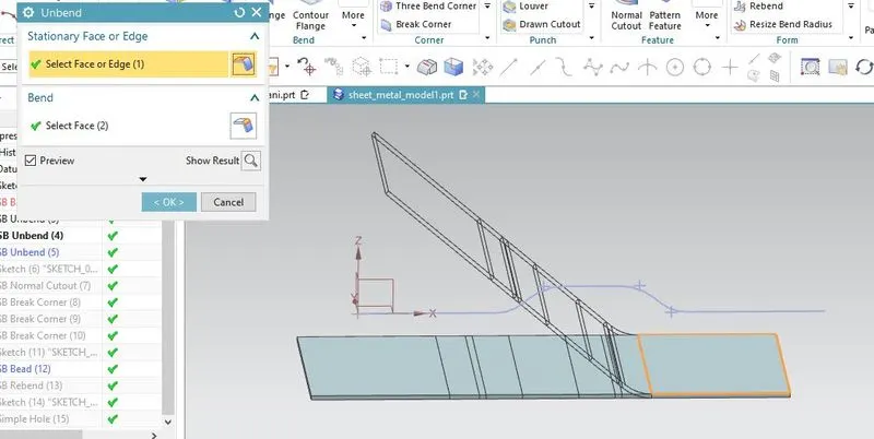
now to create the features like beads and holes the surface is unbend.
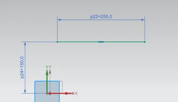
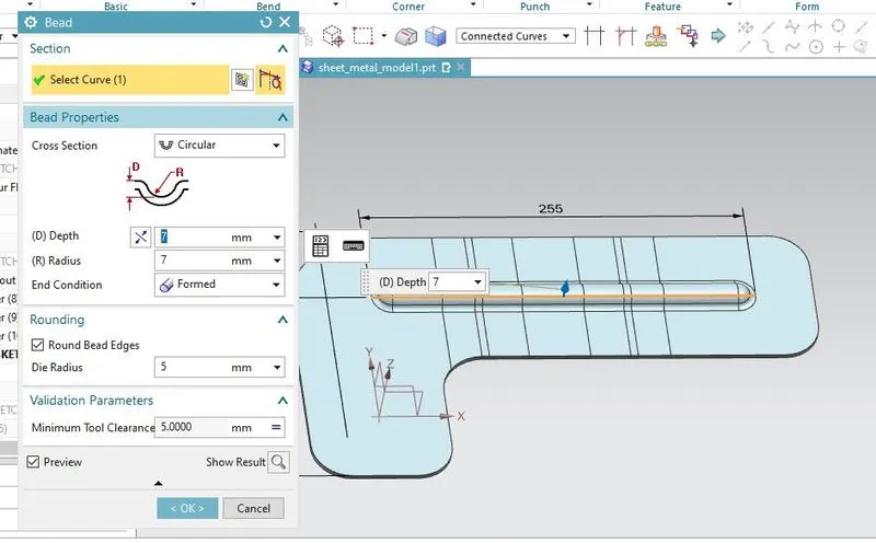
go to bead ,select the curve radius and depth of 7mm is given.
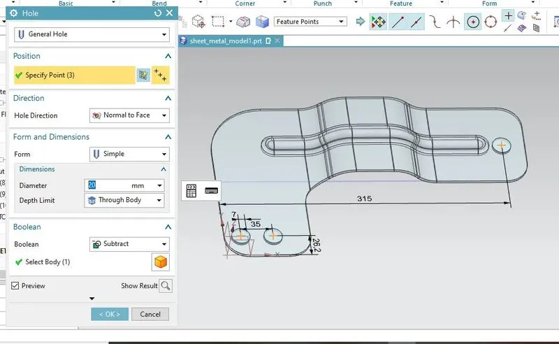
create point for hole.go to hole command select the points radius of 10 cmm is given
flat patternis given by select flat pattern command and select the face
go to mode views to view the flat pattern
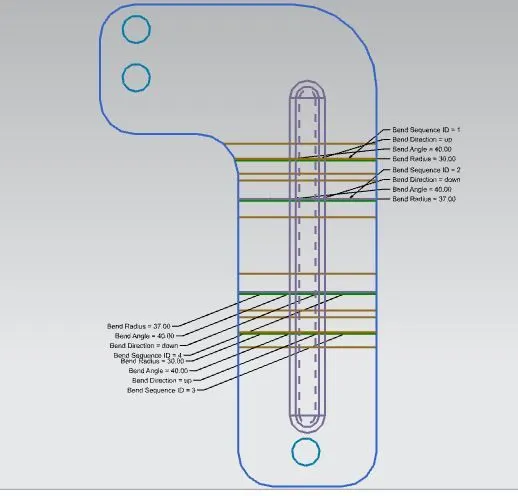
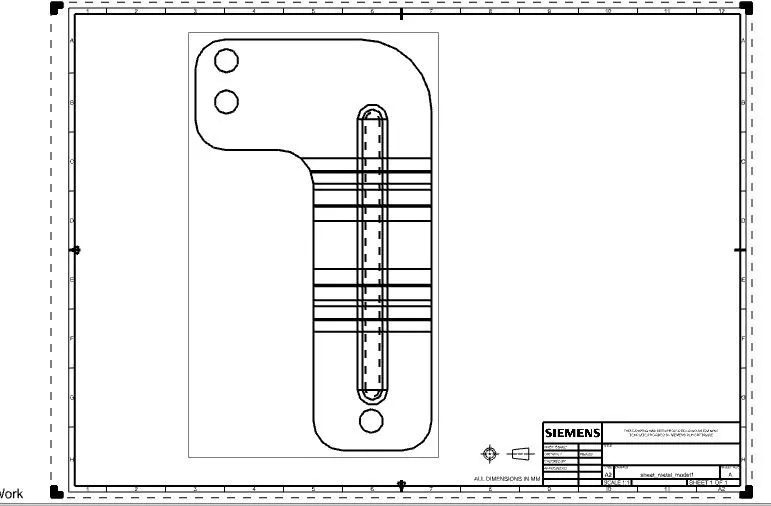
drawing
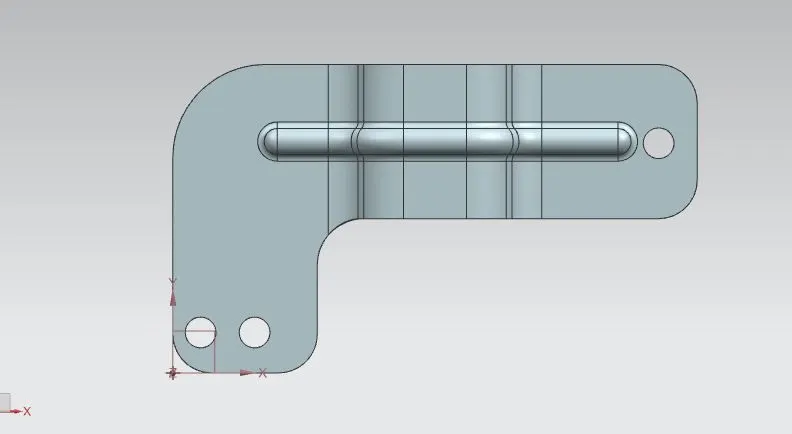
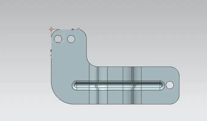
model views of final part
CONCLUSION: thus the bracket is created in NX cad sheet metal with required output