Advanced Sheet Metal Design Using NX Cad Challenge_6_Bracket
CREATE A BRACKET
OBJECTIVE:-
Create a bracket using NX sheet metal design.
INTRODUCTION:-
I created bracket by using various command like counter flange, Normal cutout, Bead, Break Corner, Unbend, Rebend, Simple Hole.
DESIGN METHODOLOFY:-
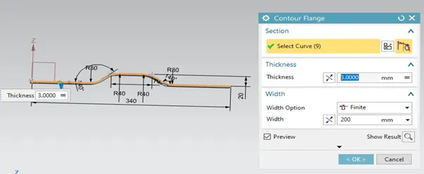
- Make a Counter Flange with 200 mm width and 3 mm thickness.
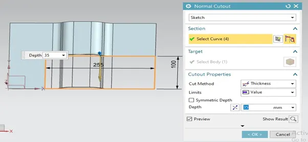
- Make Normal Cutout of 35mm Depth.
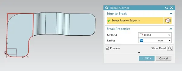
- Apply various break corners to remove sharp edges.
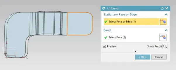
- Unbend the sheet metal at following surface.
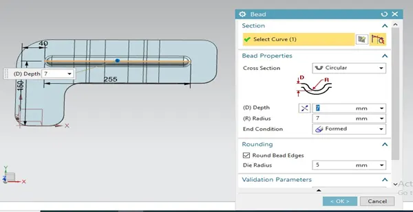
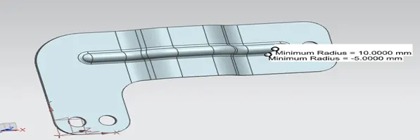
- Apply a Bead and measure a radius as shown in fig.
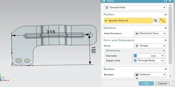
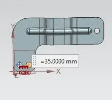
- Make three 20 mm dia. General hole as shown in figure.
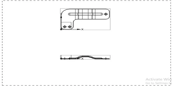
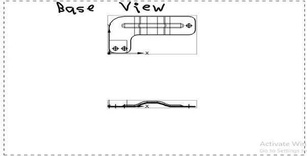
7. Apply Base View using drafting.
Description:-
- Unbend:- Usethe Unbendcommands to unbend and rebend non-uniform thickness bends.
- A General Size Hole :- This command use for create a general size hole in sheet metal.
- 3. Bead:- Use the bead command to lift material along the contour of a sketch that simulates a stamping tool. Beads can also be created to stiffen sheet metal part.
- 4. Rebend:- Usethe Rebendcommands to unbend and rebend non-uniform thickness bends.
- Break Corner:- Use this command to round or chamfer sharp corners.
- Counter Flange:- Use the counter flange command to create a flange by extruding a sketch along a vector or by sweeping a sketch along an edges or chain of edges.
- Normal Cutout:- Use the normal cutout command to cut material by projecting a sketch onto the model and then cutting perpendicular to the faces intersected by projections.
Various views in CASING DESIGN:-
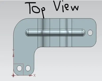
- Top view:-
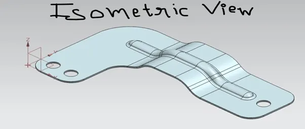
- Isometric View:-
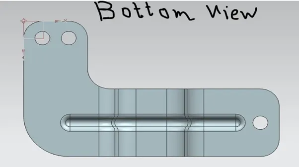
- Bottom view:-
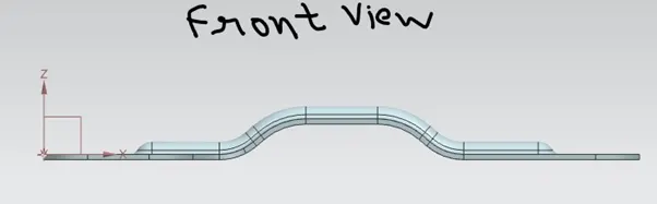
- Front View:-
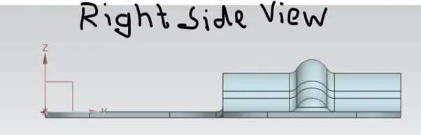
- Right Hand Sided View:
- Base View by DRAFTING.
Conclusion:-
By using various commands I created a BRACKET.
Google Drive Link
https://drive.google.com/file/d/1LIAAl1LlY0S9hEw1hDyS7pXEJGq-yRLR/view?usp=sharing