Advanced Sheet Metal Design Using NX Cad Challenge_5_Odd Shaped Enclosure
Odd Shaped Enclosure
Objective:
To design the odd-shaped enclosure in sheet metal by using NX 12.0
Introduction:
We design the odd-shaped enclosure by using the NX CAD software.
We mostly used features such as Sketch, Extrude, Sheet Metal from Solid, Flange, Jog, Unbend, Bead, Hole, Rebend, and Flat-Pattern.
In this design, a drawing sheet needs to be drafted for an odd-shaped enclosure by using a drawing application in NX 12.0.
Design Methodology:
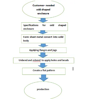
This design considers the features such as Extrude, Sheet Metal from Solid, Flange, Jog, Unbend, Bead, Hole, Rebend, Flat Pattern and drafting. The design methodology used for this challenge can be summarized as depicted in the flowchart mentioned above image.
Description:
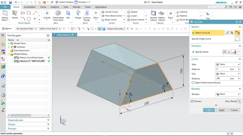
Extrude:
It is used to extrude by using the 2d sketch.
I created extrude with 200 mm length normal to the ZX plane
Sheet Metal from Solid:
It is used to create a sheet metal from a solid body.
Flange:
It is used to make a flange on the solid body.
It is created flange with 20 mm length on the solid body.
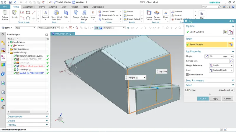
Jog:
It is used to create a jog on the solid body.
It is created jog with 20 mm length on the solid body.
Unbend:
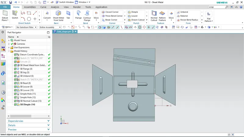
Unbend is a very useful tool in the NX-CAD. In the Unbend dialogue box, select as stationary face the larger horizontal face of the metal sheet.
It is used to unbend on the solid body.
Bead:
Bead is created to conture shape according to the sketch in the required direction with a required punch.
It is used to make bends on surfaces.
Hole:
Hole Feature can be created simple, screw clearance hole and a fit.
set the depth limit option to through the body.
It is used to create a hole in the sheet metal body.
Rebend:
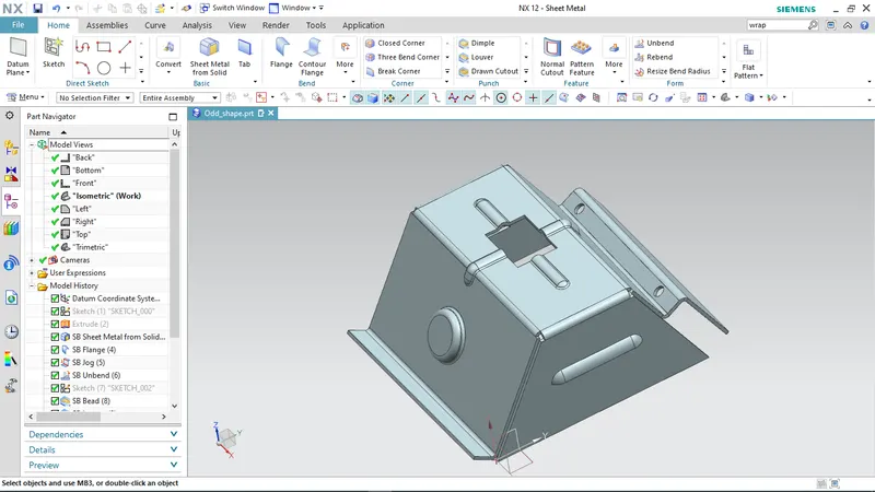
It is used to make an original shape to sheet metal body by using the rebend.
Rebend is used to bend from the unbend parts.
Flat-Pattern:
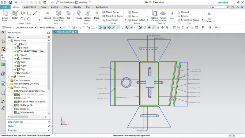
Select the central face of the metal sheet and validate.
Flat-pattern is the representation of the entire sheet metal component.
It removes the possible such as interference or collision within the same component.
It is used to make a flat form of component.
Draft drawing:
After the modelling, the manufacturing of the component a technical 2D drawing of the component with accurate dimensions or scales is denoted.
The draft is created with a scale of 1:1and using A4 size. and add a new Base View.
In the Base View dialogue box, select the option Model View to use FLAT-PATTERN#1.
Set the scale ratio is 1:5.
Final Conclusion:
This odd-shaped enclosure design has been completed by using the sheet metal application in Siemens NX CAD.
Then the required drawing sheet was created by using the draft application in the NX-CAD.