Advanced Sheet Metal Design Using NX Cad Challenge_2_Box Assembly
MY NAME - ABHISHEK VERMA
CHALLENG NAME -BOX ASEEMBLY.
Objective-:)The goal of this challenges is to use UG NX Sheet Metal application where we prioritize the tools .we use to build Box Assembly.
Introduction-:) Sheet Metal is Metal formed thin ,flat pieces by an industrial process .Sheet Metal is one of the Fundamental forms used in metalworking and con be cut and bent into a wide variety of shapes. countless every day objects are made from sheet metal NX CAD is design software. countless every day object are are made from sheet fact that it is important to build a proper component in the mechanical industry .It is also a fact that using sheet metal for complex designing is very difficult and this software comes in handy to overcome the difficulties and helps us visualize .How the component is going look like for the manufacturer .Features like unban and drafting come of the martials are as follows. JSC270DU,JSC270CC ,JSC590RN JSC780YLN and JSC1180YLN , etc.
Box is sheet metal component that is obtained by using features such as tabs flanges ,cutout ,etc. and the design of box is done by following process of cutting , bending ,punching , welding ,rolling ,forming .etc.
Design Methodology-:)
| Apply flange and Hem flange to a create a circular profile with 5mm where the hinge to be fixed. |
| Un band the by using un bend feature create a sketch to cutout the profile by using normal feature and Rebend the profile. |
| Mirror the profile with the reference to the mid plane to form a replicate of existing body. |
| Repeat the same steps on top side of the box by creating flange ,hem flange to create circular profile unbend the part a create a sketch to cutout the profile. |
| Select the flat pattern and create a new Drafting fine of A4 size and add base view |
Description -:) All the tools and process used while designing the Box Assembly are as Follows.
SKETCH-:) Adds curves ,Dimension And constraint to plane or face
EX- sketch about the XY plane of Rectangle to create the base Feature.
TAB-:) Creates a base feature by extruding a sketch along a Vector Material to Planar face
EX-: The Extrusion of the Rectangular sketch.
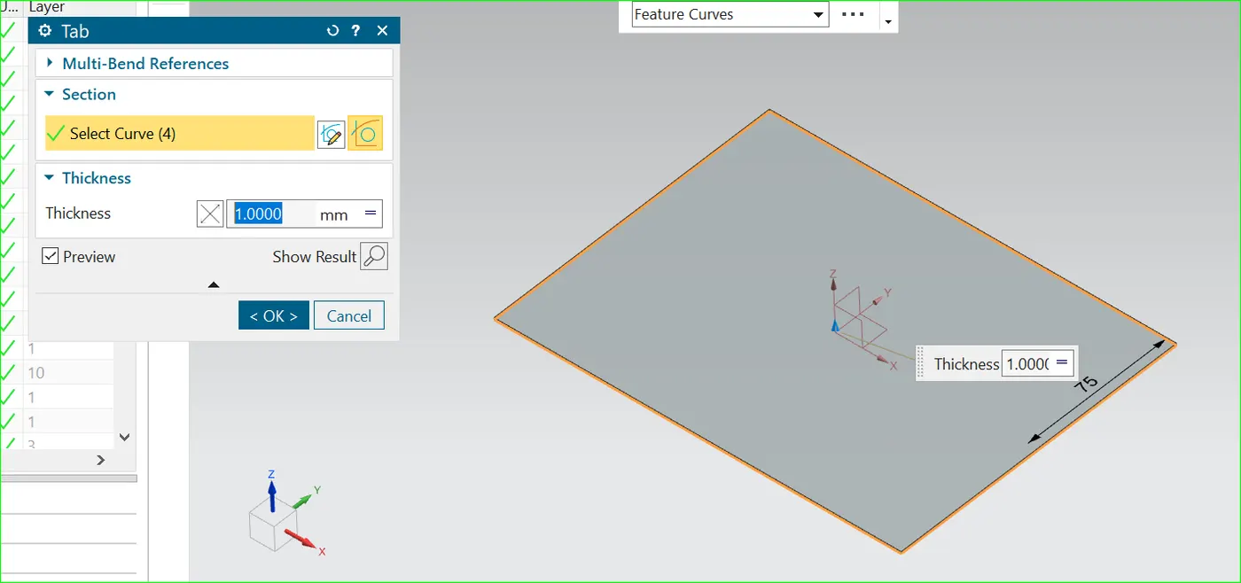
Normal Cutout-: cut material by projecting a sketch on the model and then cutting perpendicular to the face intersected by projecting ..
Ex- To cut a Rectangle of the flange for hinge..
Hem flange -: Modifies the model by folding the edge of a sheet metal flange over onto itself ..
for the purpose of safe handling or to incase edge stiffness .
Ex- top edge to flange..
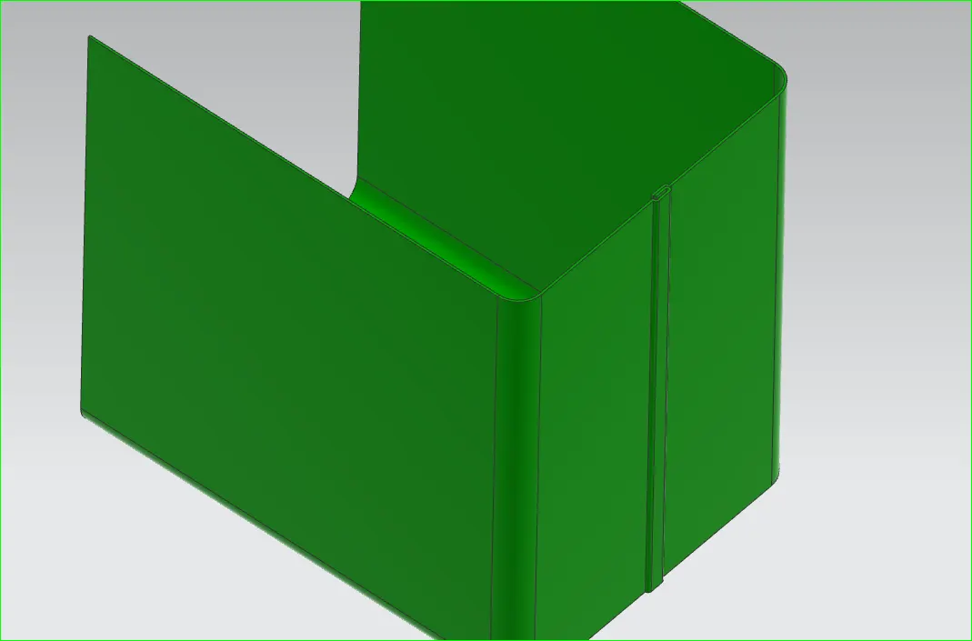
step 3- create a Half body and use to sheet metal commend and use to mirror feature and use to unit commend complete the box base are .
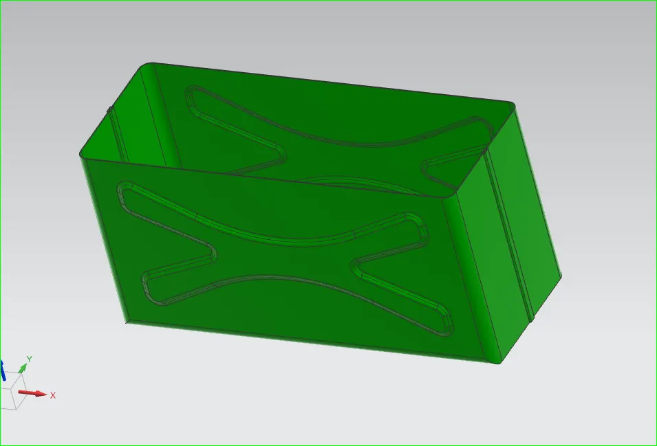
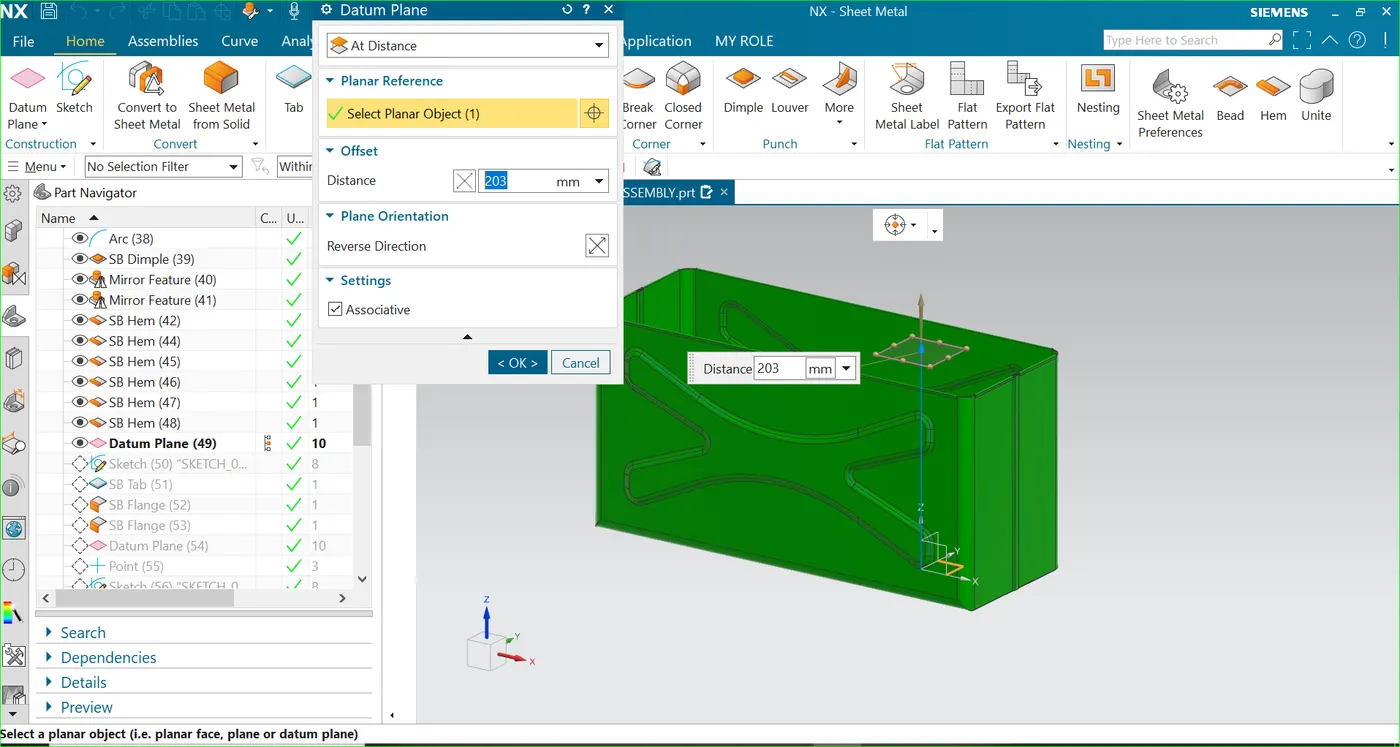
Step 4-: Creates a datum plane used to construct other above XY plane for the top of the box.
Flange -: Adds a flange at an angle to a plane face and add flanges to the edges of the tab to create the side walls.
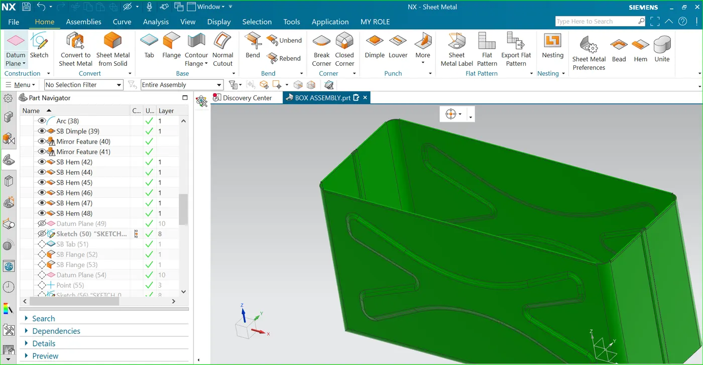
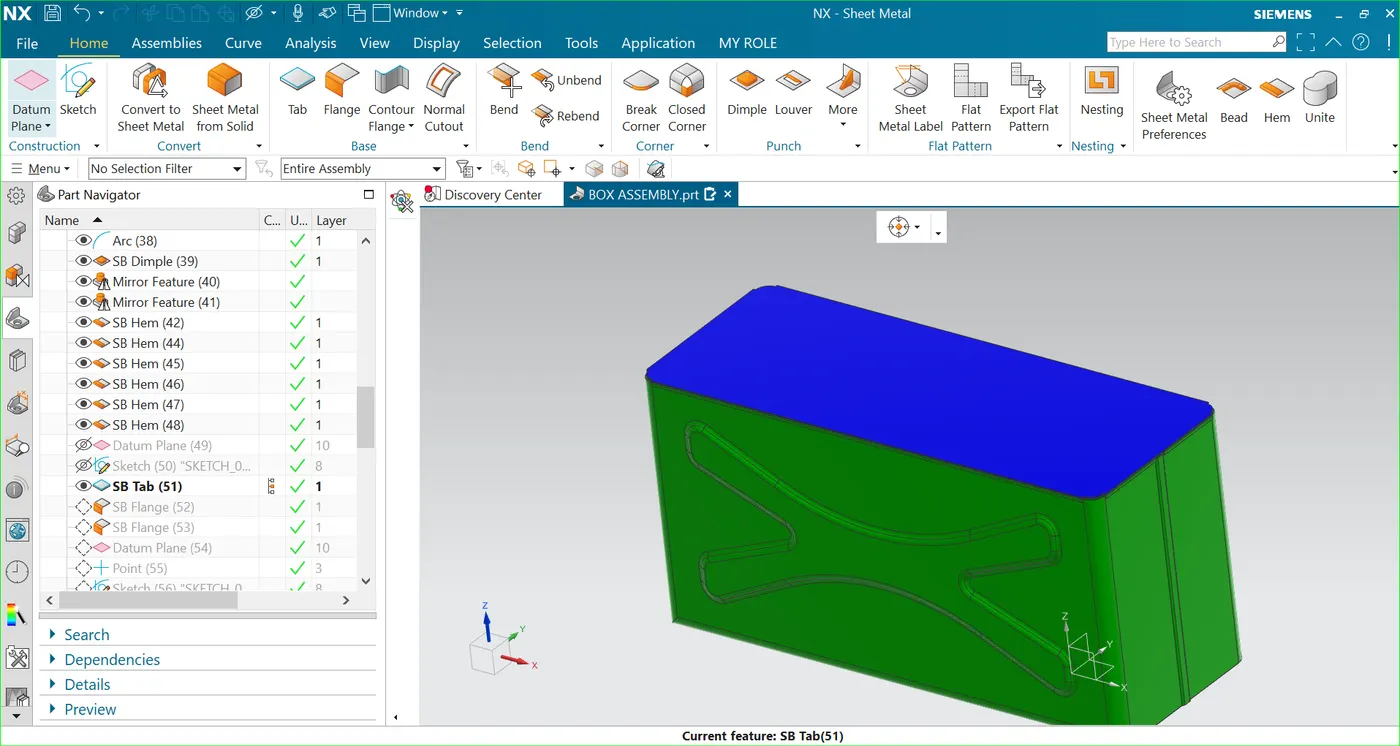
DRAFTING -: Application with tool to a create and maintain drawing with dimensions of the base view ...
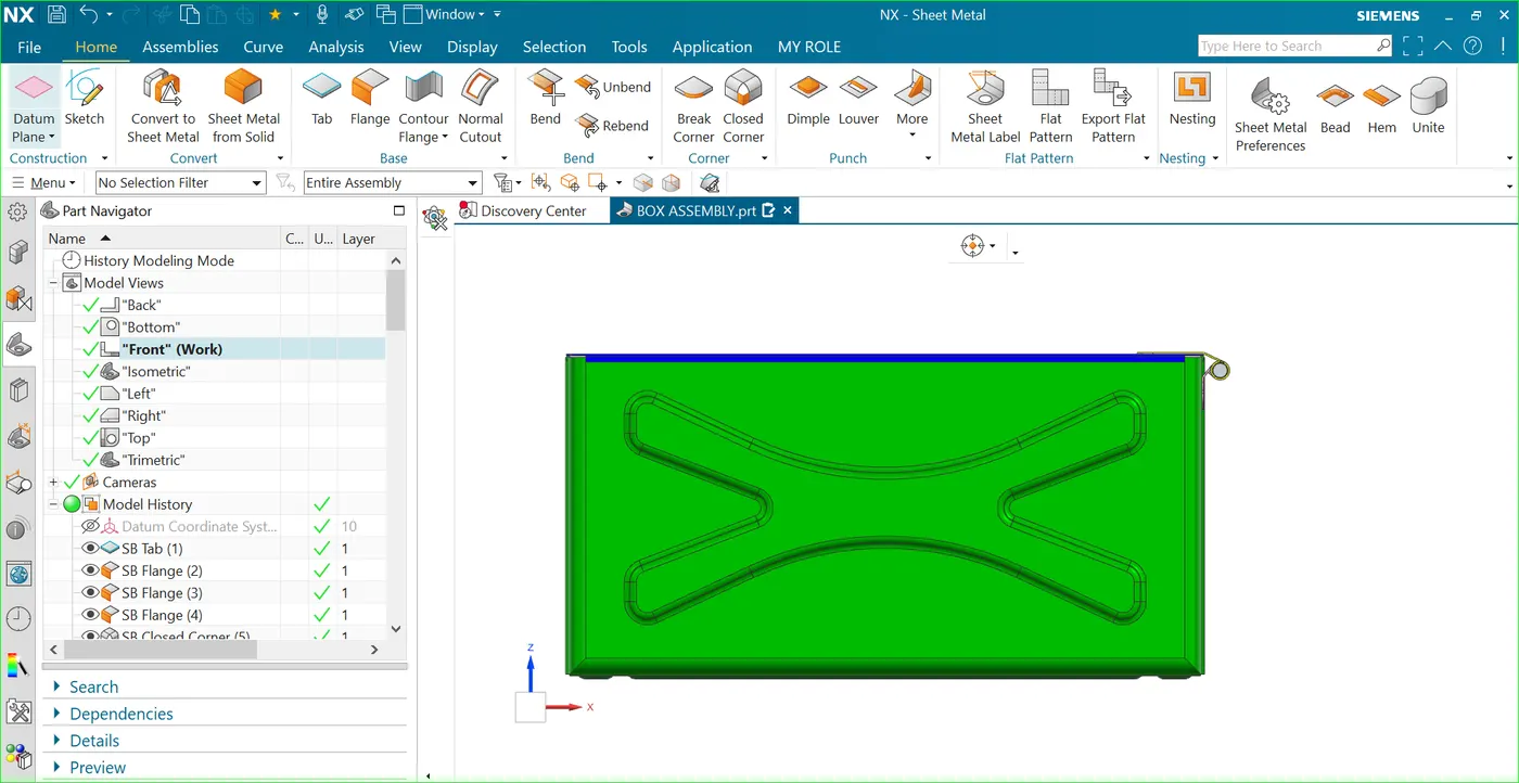
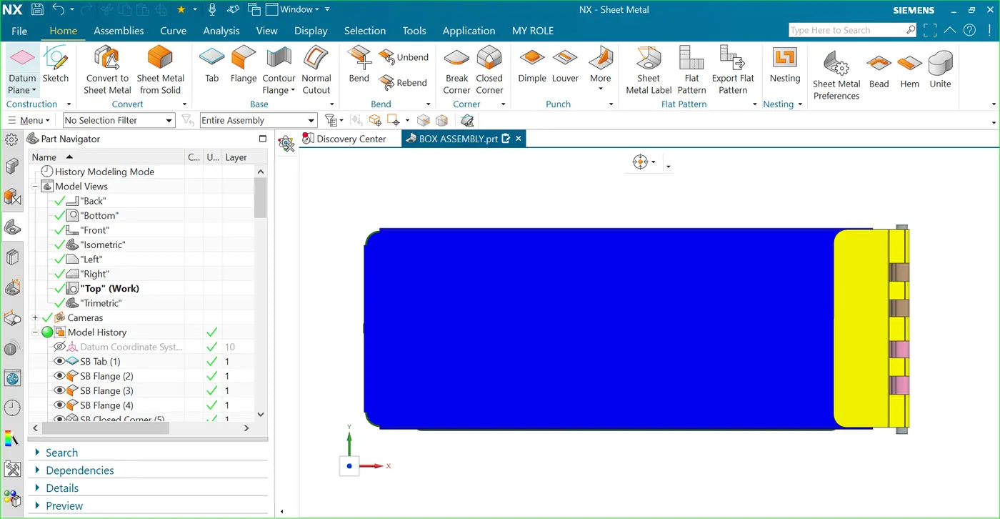
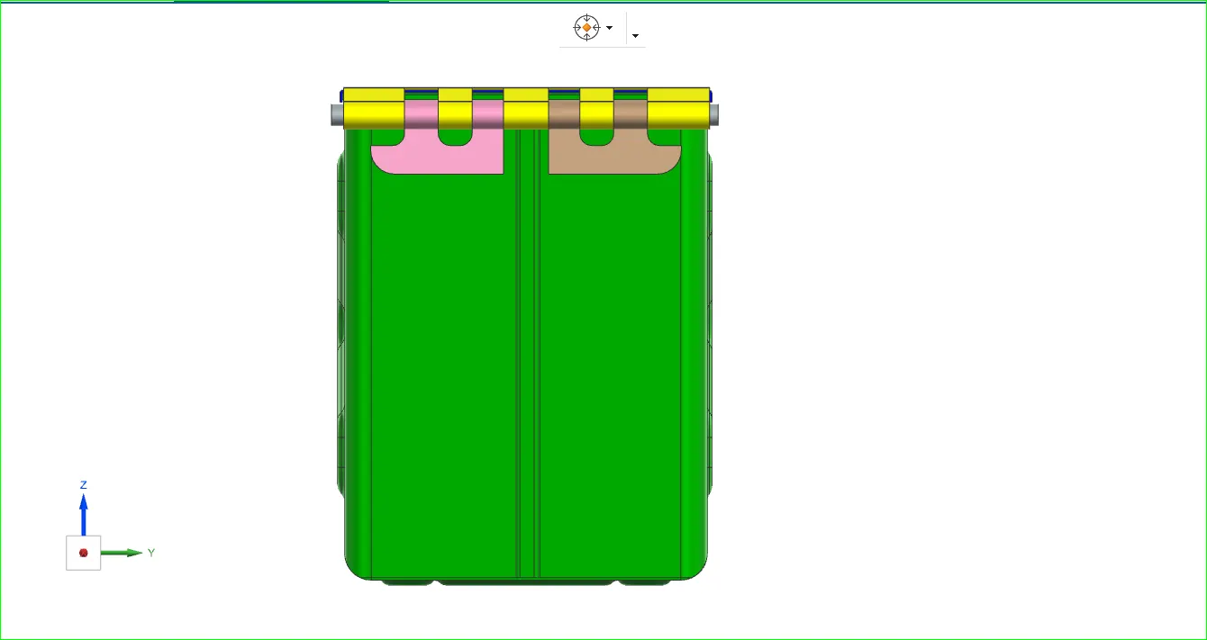
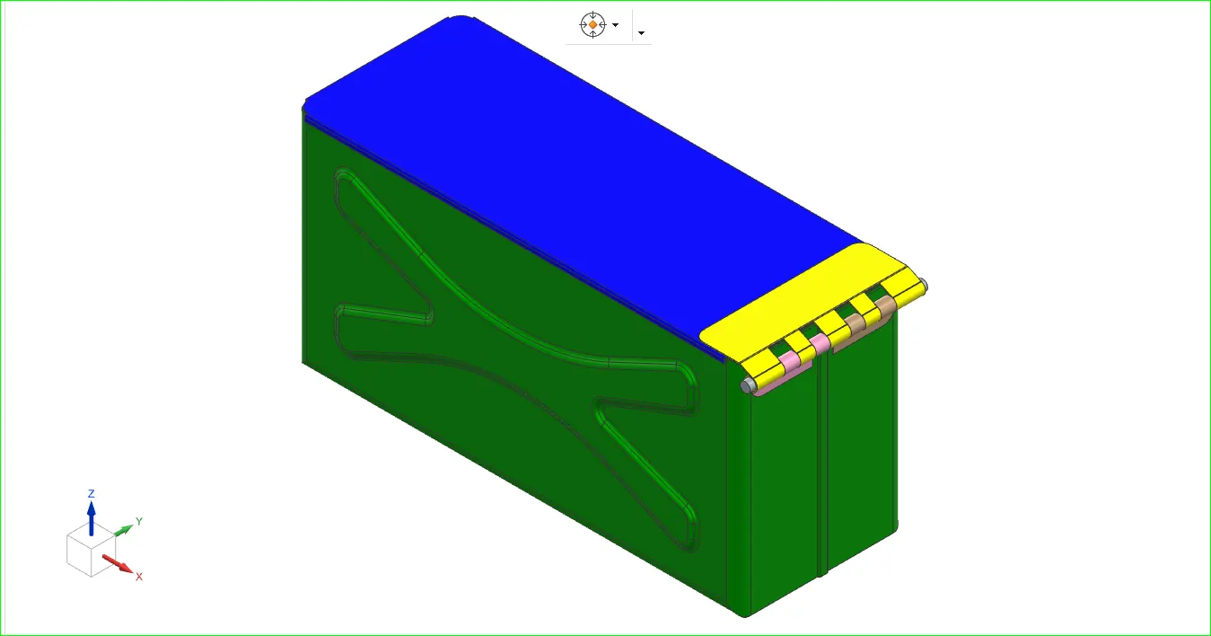
IMAGE OF THE BOX ASSEMBLY-:
Front view -:
Top view-:
Side view-:
Isometric view-:
Thank you !!