Advanced Sheet Metal Design Using NX Cad Challenge_2_Box Assembly
...
...
Challenge 2
Box Assembly in advanced sheet metal design using NX CAD
Objective:
To create Box Assembly in advanced sheet metal design using NX CAD
Introduction:
Sheet metal which has various advantages like metal working, manufacturing and easy to work on operations such as bending,cutting during industrial process.Box assembly design has different parts to create a closed enclosure.
NX CAD sheet metal design is a comprehensive set of tools for creating and manufacturing sheet metal parts. It includes features for:
- Creating sheet metal parts: You can create sheet metal parts from scratch or by importing flat patterns. NX CAD provides a variety of tools for creating flanges, bends, hems, and other sheet metal features.
- Flattening sheet metal parts: NX CAD can flatten sheet metal parts to create accurate flat patterns for fabrication. This is important for ensuring that the parts can be manufactured correctly.
- Analyzing sheet metal parts: NX CAD can analyze sheet metal parts to identify potential problems, such as kinks, tears, and wrinkles. This can help to prevent problems during the manufacturing process.
Here are some of the key features of NX CAD sheet metal design:
- Flange: Creates a flange, which is a bent piece of sheet metal.
- Bend: Creates a bend, which is a corner in a sheet metal part.
- Hem: Creates a hem, which is a folded edge on a sheet metal part.
- Hole: Creates a hole in a sheet metal part.
- Relief: Creates a relief, which is a cutout in a sheet metal part.
- Bead: Creates a bead, which is a raised ridge on a sheet metal part.
- Unbend: Unbends a sheet metal part to create a flat pattern.
- Flatten: Flattens a sheet metal part to create an accurate flat pattern.
- Analyze: Analyzes a sheet metal part to identify potential problems.
NX CAD sheet metal design is a powerful tool for creating and manufacturing sheet metal parts. It is used by engineers and designers in a variety of industries, including automotive, aerospace, and electronics.
Design methodology / approach (To be explained with the help of Flowcharts only)
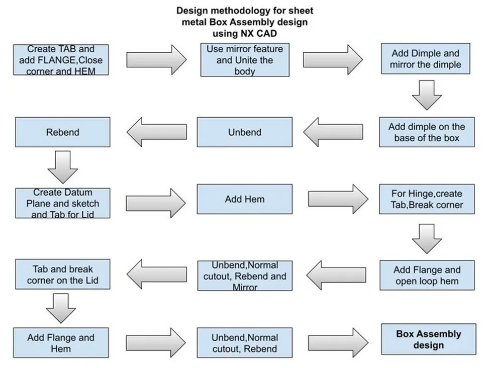
Description (Need to explain tools/ Features used while designing)
- Main box:
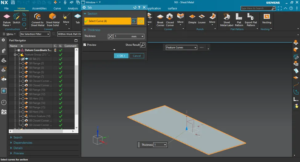
- Tab: Draw the sketch and add thickness of 1 mm
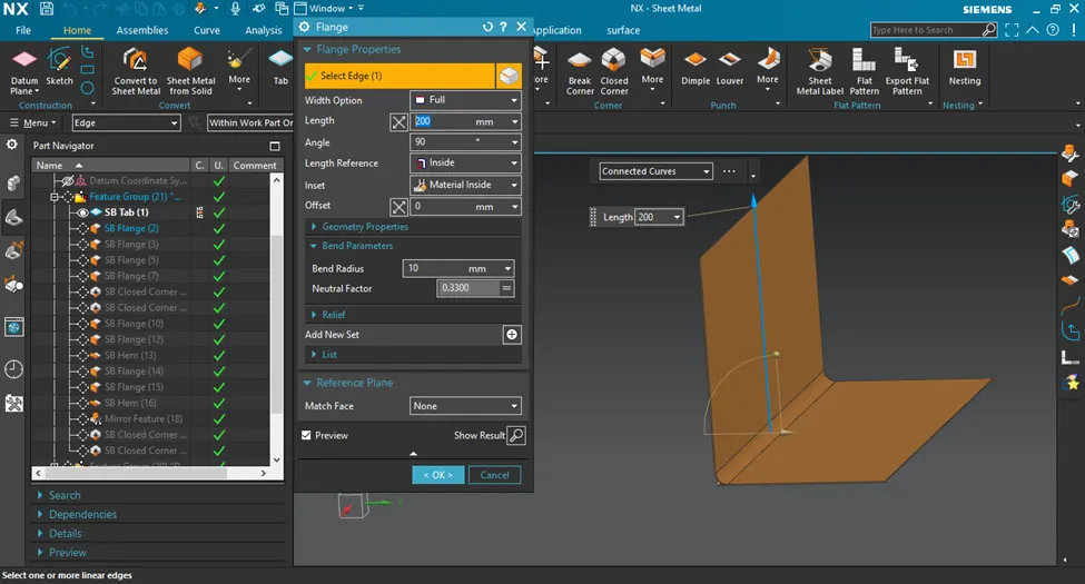
- Add flange: Flange with bend radius 10, angle 90 deg and length of 200 mm
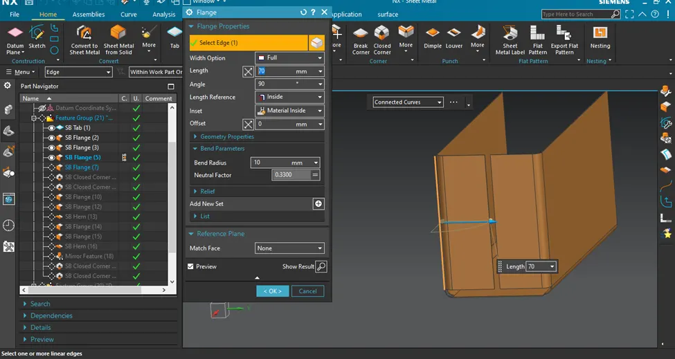
* Flange with length 70 mm sides
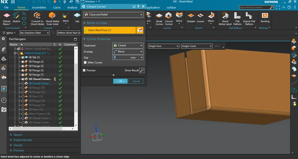
- Close corners: close and relief option used to close corner
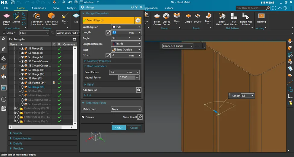
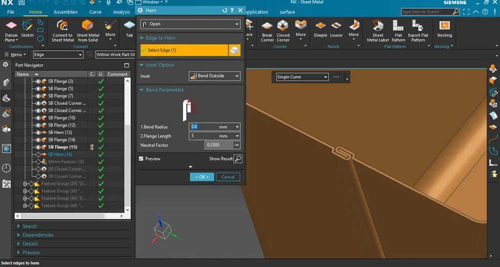
- Add flange and hem
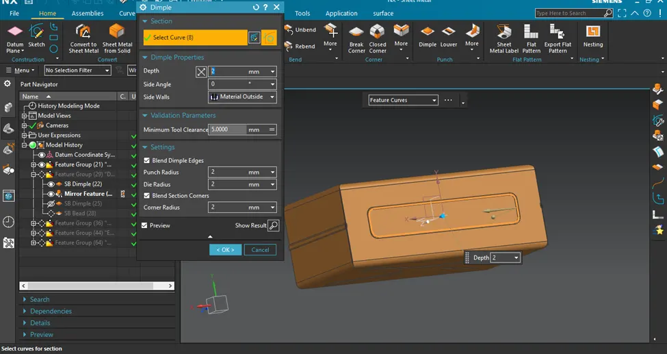
- Add dimple: sketch and use depth of 2 mm for the dimple
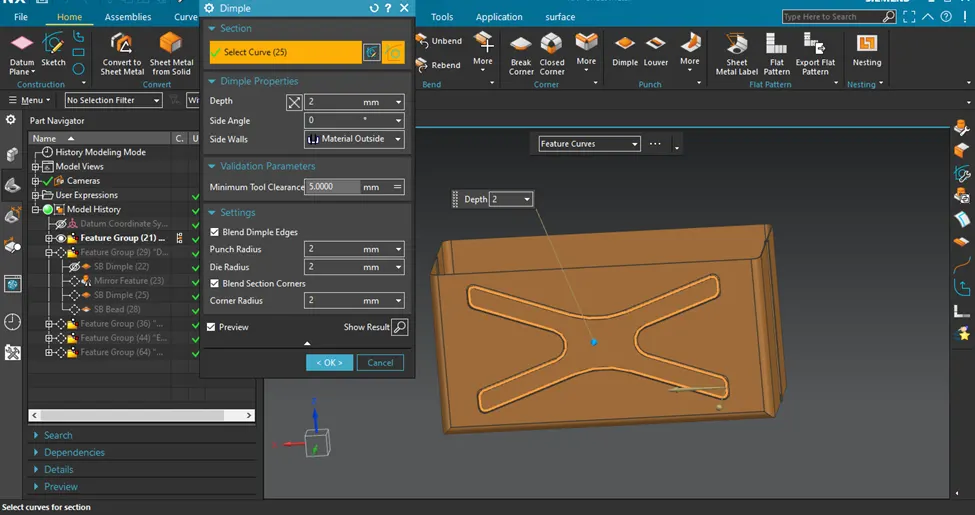
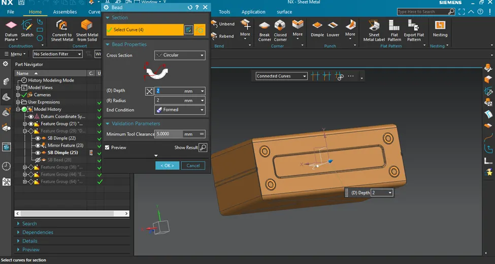
- Add bred: Depth and radius of 2mm and mirror the bred feature
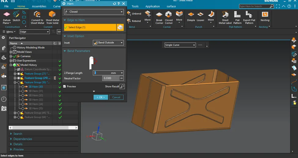
- Add hem:
2.Lid
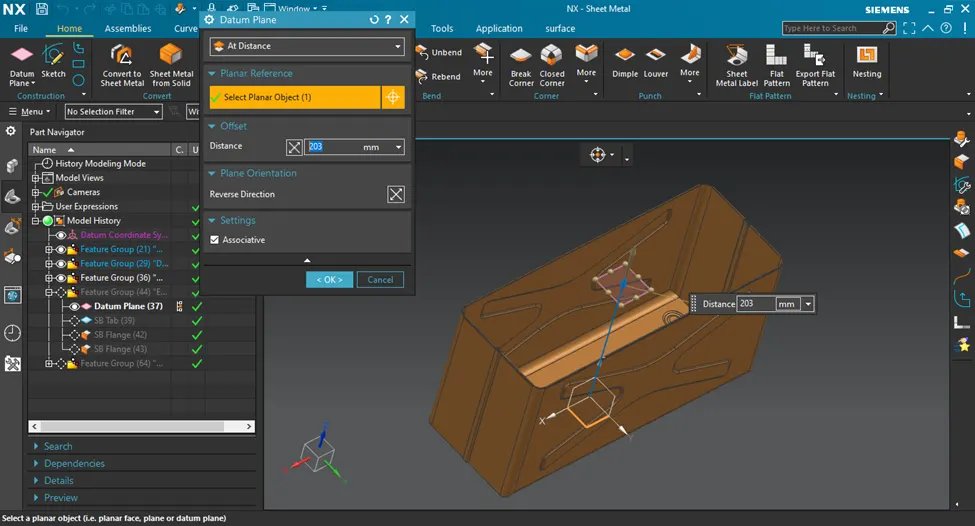
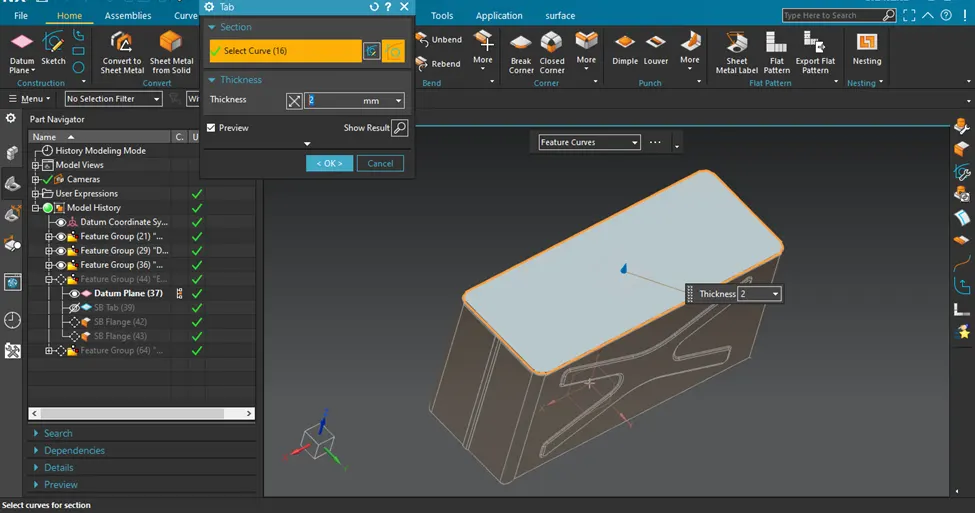
* Use Datum plane at a distance of 203 mm
- Tab:Sketch and add tab thickness 2 mm
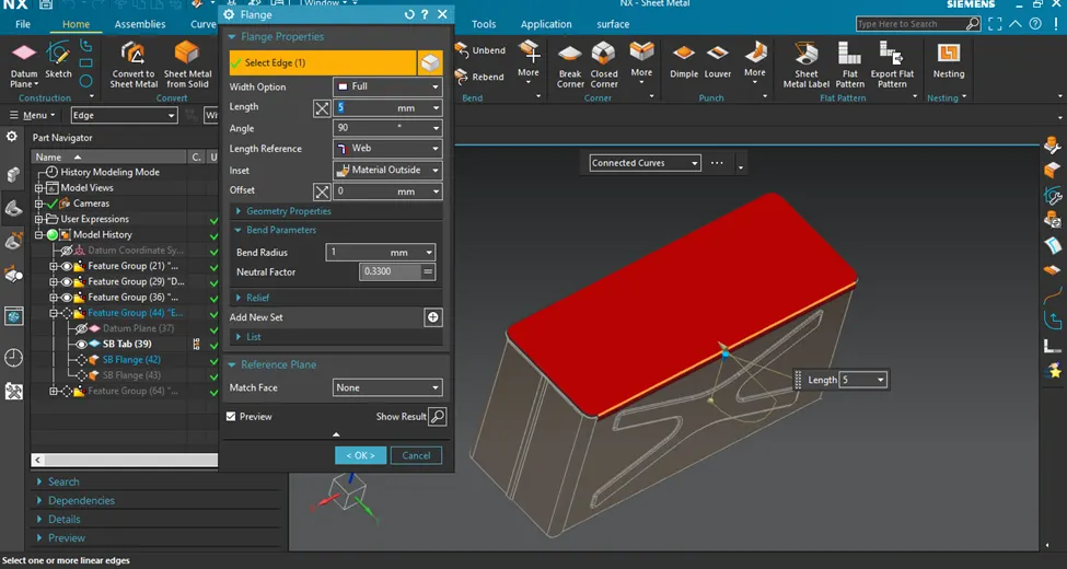
- Add flanges:It is added to the sides of the Lid component
3.Hinge
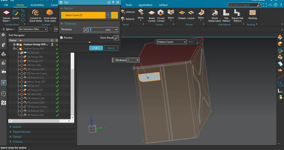
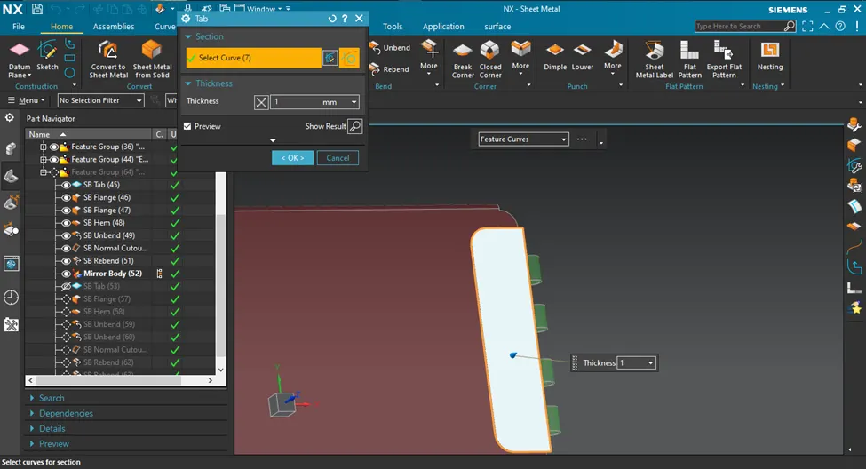
- Tab:Sketch and add tab thickness of 1 mm
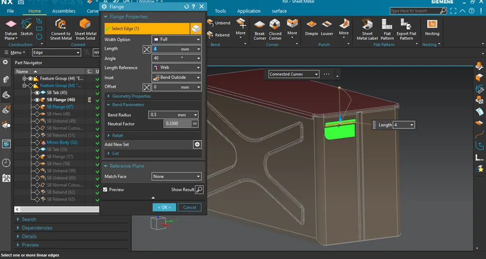
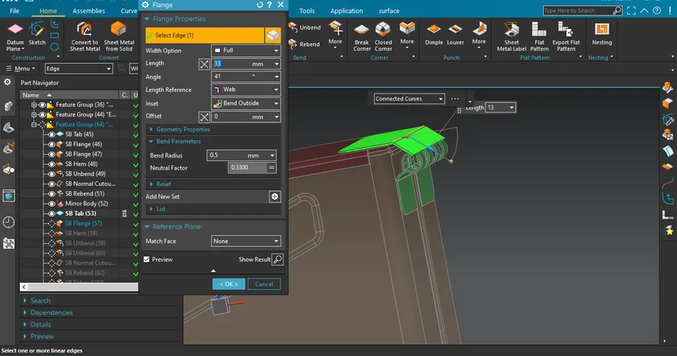
- Add flange:Flange with 40 deg and length 4 mm is given
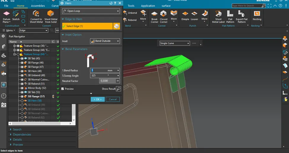
- Add open loop hem: Bend radius 5 mm and sweap angle 325 deg is given
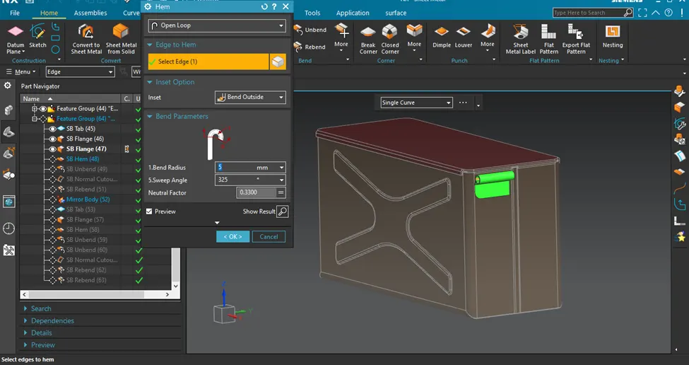
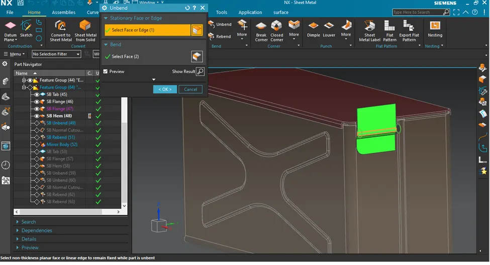
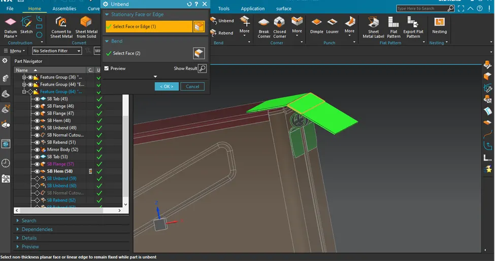
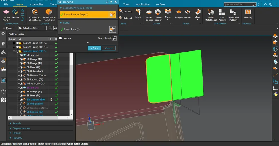
- Unbend
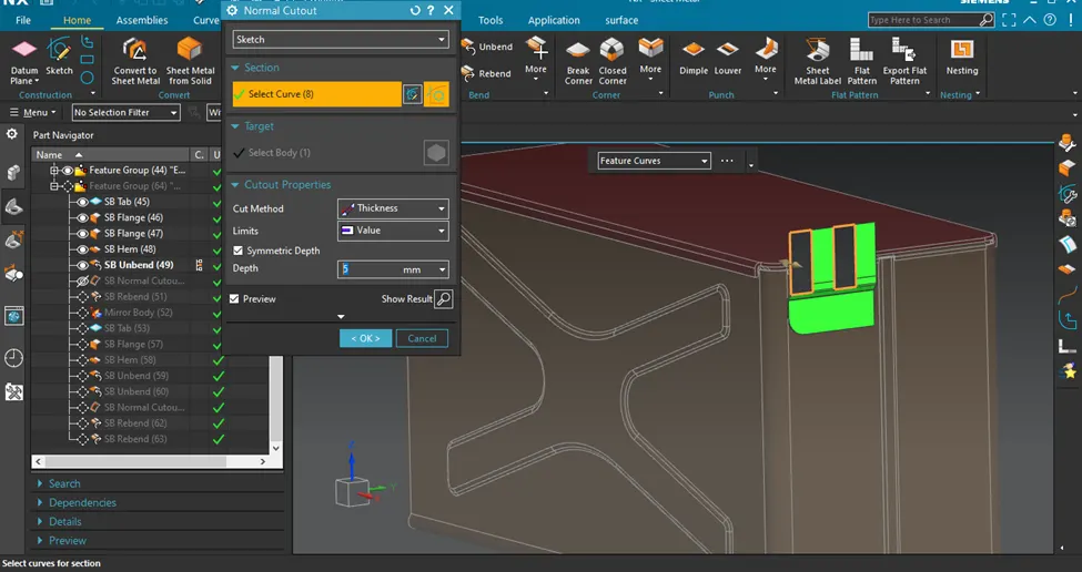
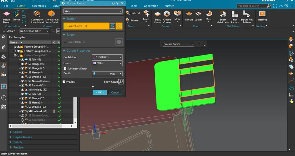
- Sketch and Normal cutout:Cutout having depth of 5mm
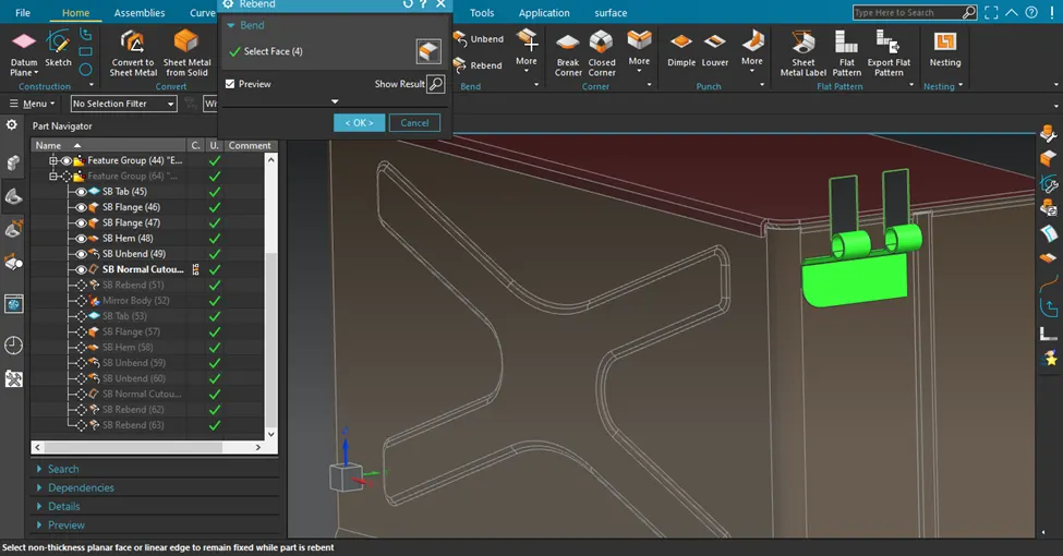
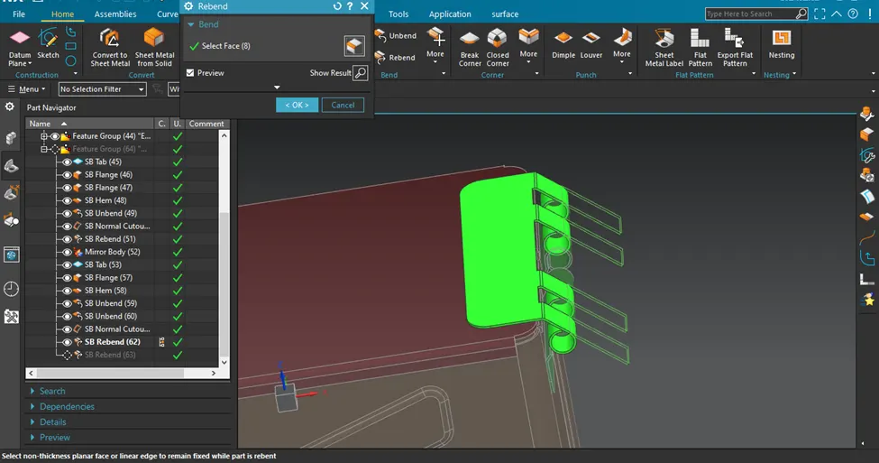
- Rebend:Rebend after normal cutout feature
- Mirror body: Mirror the body using XZ Plane
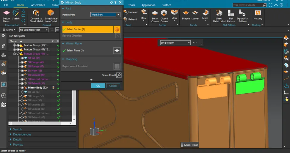
- Tab: Sketch and add thickness 1mm
- Add flange:flange having bend radius 1 mm and length of 14.2 mm
- Hem: Open loop type hem having Bend radius 5 mm and sweap angle 325 deg
- Unbend:To sketch and cutout material
- Normal cutout:Remove material from the tab
- Rebend:To form the hem that was created
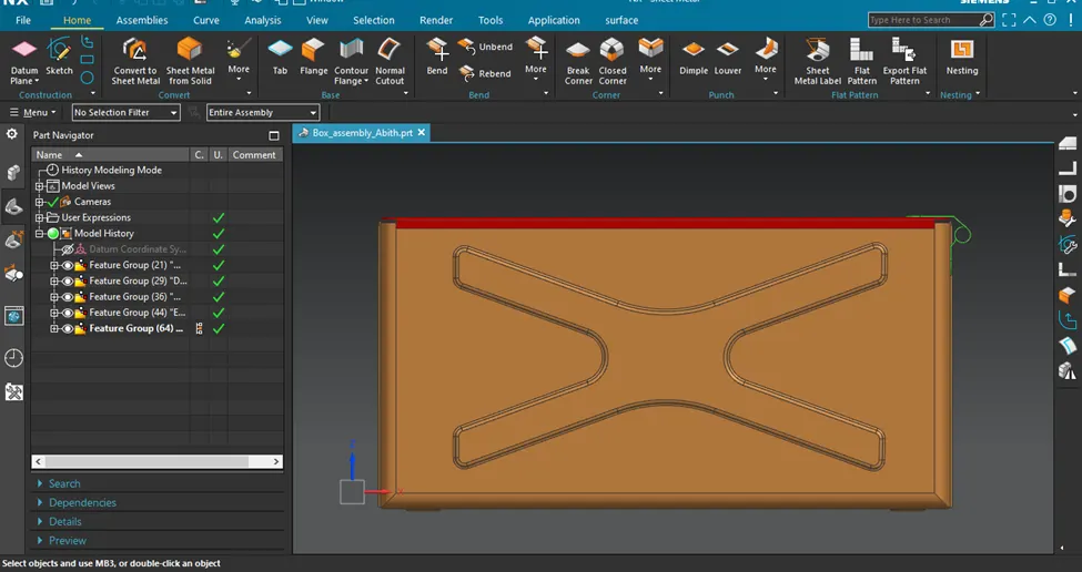
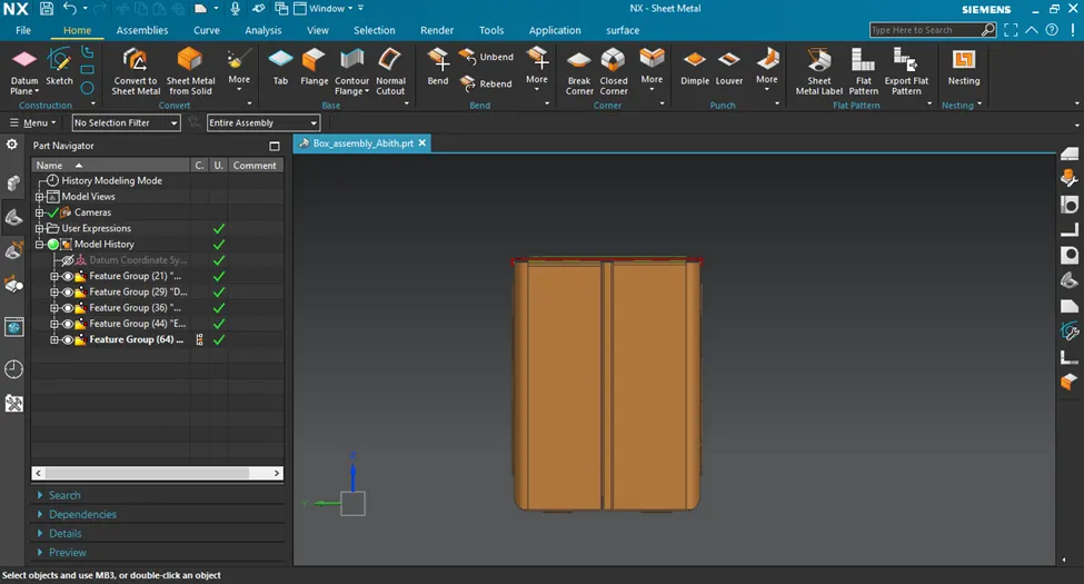
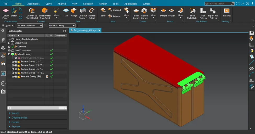
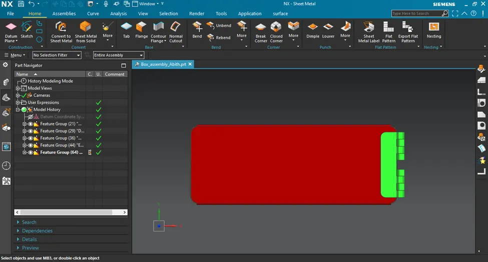
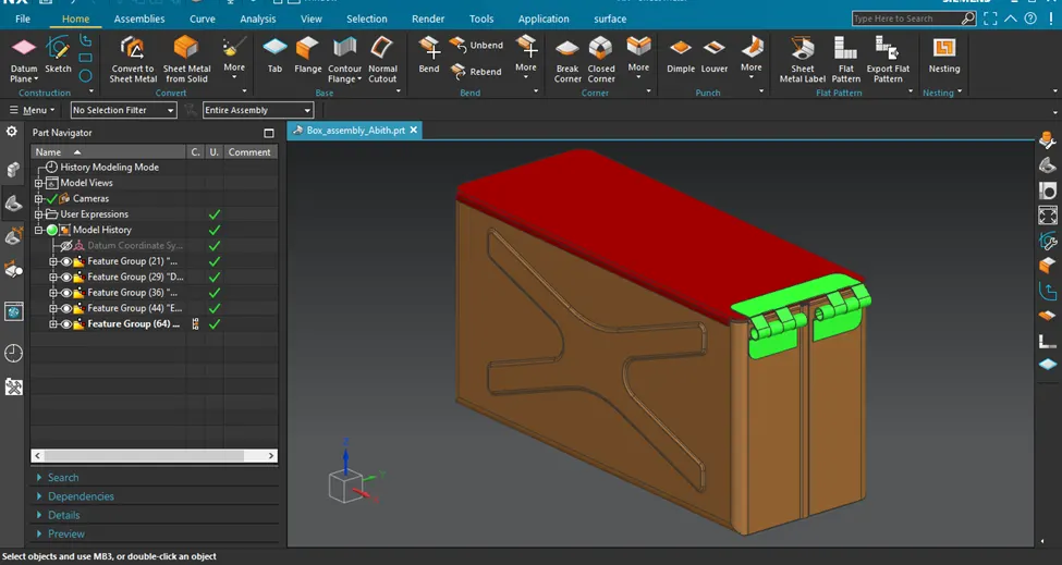
Screenshots of Model in various orientations
Front View
Side View
Isometric View
Top View
Bottom View
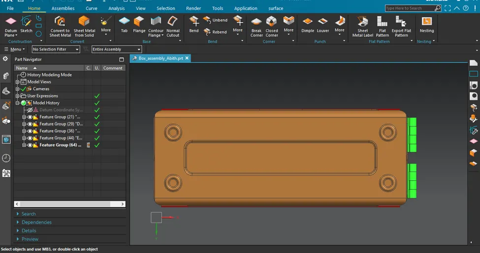
Trimetric View
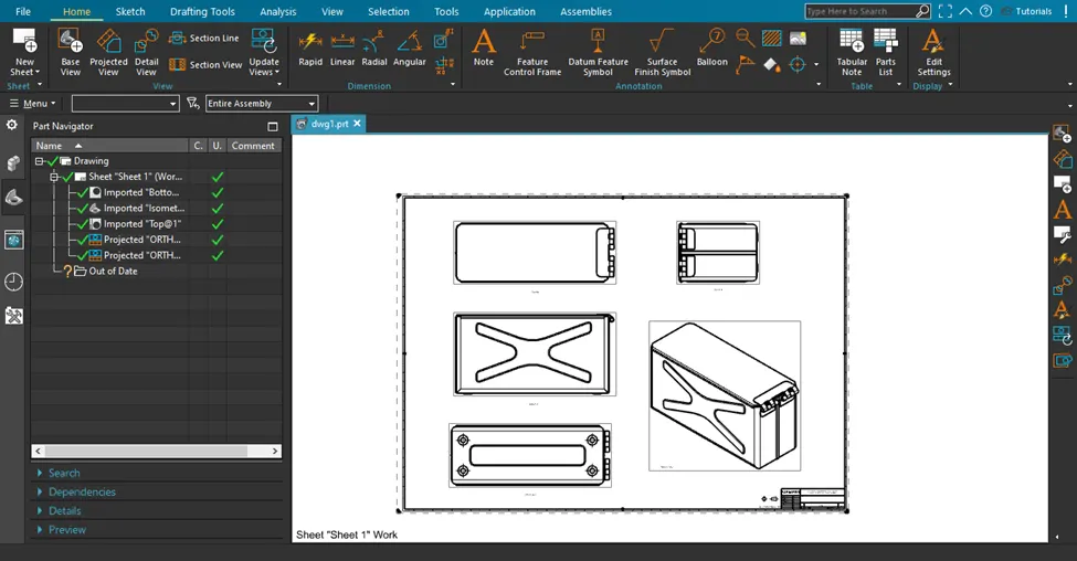
Attach Detailed Drawing Sheet Image (If Required)
Sheet 1 contains Front view,Top view,Side view and Isometric view
Conclusion
Box Assembly design in advanced sheet metal design using NX CAD is completed .
NOTE: The box assembly NX CAD file saved as "NX_Box_Assembly Abith" with extension ".prt" is attached.